1
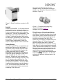
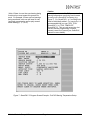
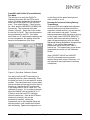
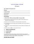
Monitoring Bearing
Temperature with
ProPAC
Introduction
A mechanical stamping press usually has two
or more main bearings for supporting the
crankshaft and for allowing smooth and
accurate rotation. There may be other
important bearings on your press, such as a
flywheel shaft bearing. Proper lubrication
along with periodic inspections to detect
excessive wear along with verification of
correct clearance is an essential part of every
press’s maintenance program.
Monitoring bearing temperature when the
press is running, especially under load is
another way to reveal if a bearing is worn or
about to fail. A number of factors can
contribute to higher than normal bearing
temperatures and resulting bearing failures.
Some examples are age, lack of lubrication,
incorrect ram parallelism, operating the press
over capacity, improperly adjusted
counterbalance pressure and worn-out dies.
This application note will discuss how to
measure and monitor bearing temperature
using one or more RTDs (Resistance
Temperature Detector), one or more Signal
Conditioners and ProPAC (a SmartPAC
module).
Some basics about RTDs
An RTD is a simple metal element formed of
platinum, nickel, or a nickel-copper alloy known
as Barco. It operates on the principle that
metals increase in resistivity as temperatures
increase and return to their original resistance
upon cooling. When a small voltage is passed
through the element, a voltage drop
proportional to the element’s resistance is
converted into a temperature measurement or
an output signal.
Application Note
The nice thing about an RTD is the output
signal does not need to be amplified. RTDs
are available in many shapes, sizes and
ranges for different applications. One popular
type is in the shape of a stainless steel tube
and is referred to as a probe (Figure 1).
Figure1 - General Purpose RTD probe
RTD probes are a good choice for measuring
bearing temperature due to their length, shape
and ability to be inserted into a hole and touch
the outer race of the bearing. These probes
are low in cost and are available in different
lengths and diameters as an off-the-shelf item.
Signal Conditioners
Although the output of an RTD does not need
amplification, there is still a need to convert the
signal to something that can be interpreted by
a controller. It is also necessary to supply the
RTD with a constant excitation voltage.
Fortunately, there are many off-the-shelf low
cost modules available that accept a broad
range of input signals (including RTDs) and
deliver a variety of outputs including 0-10 Vdc
4-20 mA. Compact in size, most units will
conveniently mount on a DIN rail (Figure 2)
RTDs are manufactured with a base resistance
at some temperature point. This temperature
is usually 0o C (32 o F). The most common
base resistance is 100 Ohms, which means
that if the RTD is at 0o C (32 o F), the resistance
would be 100 Ohms.
Wintriss Controls Group, LLC
Page 1
2/1/2011
The probe is installed with the use of a
Swagelok fitting. The fitting has a male pipe
thread on one end and a compression fitting on
the other. (Figure 3).
Figure 2 – Signal Conditioner mounted on DIN
rail
ProPAC
ProPAC is a SmartPAC 1 or 2 module that can
measure dimensions, angles and other part
parameters in the die. In addition ProPAC can
monitor process parameters such as bearing
temperature. There are 8 (expandable to 16 or
32) analog sensor inputs that accept a 0-10
Vdc input. High and low control limits can be
set manually or automatically with user-defined
percentages. All limits are stored by tool.
ProPAC can be programmed to either Top
Stop or E-Stop the press if a limit is exceeded.
Getting Started
Choose the right RTD for your application and
decide where and how it will be installed. If
you plan on using a General Purpose Probe
(Figure 1), it is important that the probe’s tip
makes solid contact with or is slightly
embedded into the outer race of the bearing.
Probes are typically available in sizes from 6”
to 24“ in length and 1/8, 3/16 or 1/4” in
diameter. Unless there is an unusually long
distance to reach the bearing race, the 6” long
by 1/4” diameter probe should be fine. The
number of wires or leads in the circuit is also
an important consideration. A three-wire RTD
is a good choice because it typically allows up
to 36” of travel before being terminated. The
third wire compensates for lead resistance by
subtracting it from the circuit.
Wintriss Controls Group, LLC
Figure 3 – Threaded male tubing fitting
Suggested Supplier: Swagelok
Swagelok P/N (2507-400-1-4)
Find a flat area on the bearing cap that has
enough thickness to accommodate the depth
of the fitting. Calculate how deep a hole needs
to be drilled in order to reach the outer race of
the bearing. Drill and tap the appropriate size
hole for the male end of the fitting. Drill
another one, if necessary, centered inside it for
the probe (Figure 4). The hole for the probe
should be slightly larger than its diameter.
Make sure the holes are clean before screwing
in the fitting. It is also a good idea to use some
Teflon® tape around the threads first. Once the
fitting is in place remove the threaded cap from
the opposite end and slide the probe in until it
makes solid contact with the bearing race
(Figure 5). Do not tighten the end cap with the
compression fitting at this time. You will need
to remove the probe for calibration later in the
instructions.
Page 2
2/1/2011
RTD recommended specifications:
• 100 Ohm at 0 o C General Purpose
Stainless Steel Probe with Strain Relief
- 6”L x 1/4"Dia. (Note: length may vary
for each application)
• 3 wire – 36” length (Teflon®-coated wire
leads)
Suggested Supplier: Omega Engineering
Omega P/N (PR11-2-100-1/4-6-E)
Figure 4 – Outer hole drilled and tapped for
Swagelok tubing fitting. Smaller inner hole
counter bored for RTD probe
Install Signal Conditioner in a location that is
not more than 36” away from the RTD probe.
It should be mounted on a short piece of DIN
rail inside a small oil-tight enclosure (Figure 6)
Figure 6 – Signal Conditioner mounted inside
oil- tight enclosure
Note: It is OK to trim, but not extend the RTD’s
lead length. Doing so can cause the RTD to
be inaccurate or malfunction. Follow the
manufacturer’s specifications.
Figure 5 – Probe inserted into Swagelok fitting.
Probe tip touches race of bearing.
The enclosure should also be large enough to
accommodate three knockouts for 1/2” sealtight conduit. It is also advisable to install a
power indicating panel lamp and a rated fuse
(Note: run high voltage and low voltage wiring
in separate conduits. This is to keep noise
from interfering with the low voltage signals).
Wire your Signal Conditioner according to your
manufacturer’s specifications. One (1) Signal
Conditioner is required for each bearing
mounted RTD.
Wintriss Controls Group, LLC
Page 3
2/1/2011
Signal Conditioner recommended
specifications:
• 100 Ohm PT RTD Element
• 2 or 3 Wire Configuration
• 0 to 100o C input range
• 0-10 Vdc output
• 0.2% Accuracy
• 1 mA Max Excitation Current
• 110 Vac powered
• DIN Rail Mountable
Suggested Supplier: Omega Engineering
Omega P/N (CCT-20-0/100C)
Wiring the Signal Conditioner’s output
signal/s to your ProPAC’s input/s is the last
installation item to complete. Hopefully your
ProPAC has an ample amount of unused
analog inputs. If not, it can always be
expanded from 8 inputs to 16 or 32 inputs
(Contact Honeywell Wintriss or your Honeywell
Wintriss Representative to learn more about
ProPAC’s input expandability). Choose an
available ProPAC for each Signal Conditioner.
Wire according to the wiring diagram in the
back of your ProPAC User Manual and this
Signal Conditioners Data Sheet / User Manual.
Main Bearings
Probe Tip
Touching
Outer Race
Of Bearing
100 Ohm
RTD Probe
SmartPAC
1 or 2
Signal
Conditioner
0-10 Vdc
Output
Signal
Conditioner
0-10 Vdc
Output
ProPAC
Block Diagram - Main Bearing Temperature Monitoring
Wintriss Controls Group, LLC
Page 4
2/1/2011
ProPAC (Process Monitor)
Setup/Programming
After completing the installation and wiring, it is
time to set up and program the ProPAC.
(Note: The example screens shown and the
instructions used in this application example
are for SmartPAC 2 and may vary slightly if
you have a SmartPAC 1. For information
about SmartPAC 1, consult your User Manual)
Start out by accessing the Program Mode in
SmartPAC. If you already have existing tools
programmed, select one and choose the EDIT
TOOL function key
(Note: for creating new tools consult your User
Manual).
From the tool PROGRAM menu select
PROCESS MONITOR and press the ENTER
key. This will launch a list of 8 process monitor
inputs (16 or 32 inputs if your ProPAC has
been upgraded). Choose the input to which
you wired the sensor and press the ENTER
key. Next choose a name for the selected
input. Fortunately, there are 4 selections for
Bearing Temperature to select from.
Select BEARING 1 TEMP for the first bearing,
and press ENTER. Access the following
screens, entering the values for each.
SELECT THE UNITS FOR INPUT
Enter either oC (Centigrade) or oF (Fahrenheit)
(Note: For this application example oF will be
used)
SET THE RANGE /OFFSET OF THE
SENSOR
Enter the range of the RTD. In the first field
next to Range, enter 0o; in the second field
enter 330o. Leave the POSITION OFFSET
equal to 0.
(Note: The value 330 o should be a good
reference or starting point and can be checked
for accuracy later in this discussion.)
Wintriss Controls Group, LLC
SET THE SENSOR OUTPUT VOLTAGE
RANGE
This is equal to 0 to10 Vdc and is the output
coming from the Signal Conditioner.
Enter 0 in the first field and 10 in the second
field. If the Signal Conditioner has a different
output voltage (for example 0-5 Vdc), enter
that instead.
Note: ProPAC will not work with 4-20 mA
sensors.
SELECT ACTION TO TAKE WHEN THE
SENSOR EXCEEDS ITS SETPOINT LIMITS:
Choose the appropriate stop condition. For
bearing temperature monitoring, TOP STOP
should be chosen.
SET THE MEASUREMENT LOGIC
Select: CONSTANTLY MONITORED
THROUGHOUT THE STROKE.
SELECT THE SETPOINT TYPE
Select: MANUAL SETPOINT
SET THE SETPOINT LIMIT
The high setpoint is the highest allowable
temperature the bearing can reach before the
press is stopped (HIGH SETPOINT =). This
value will most likely vary and as discussed
earlier, exceeding it is dependent on a variety
of conditions. Determining an accurate value
may require some experimentation in order to
evaluate optimal temperatures under different
conditions. If you are not sure what to enter
and do not feel comfortable about taking a
guess, contact the press manufacturer for
more information. The other two fields are
LOW SETPOINT and REP (repeatable)
SETPOINT. Unless you are worried about the
bearing being too cool, leave these set to zero.
Figure 7 is an example of how your
programming may look.
Once you have all your parameters entered,
load the tool and access the Run Mode.
Page 5
2/1/2011
(Note: If there is more than one bearing being
monitored you must repeat this process for
each. For example, if there are four bearings
being monitored, each one will need its own
input and programming and be aptly named
either Bearing 1, 2, 3, or 4).
Caution
It is very important that ProPAC parameters for
bearing temperature monitoring are the same
for every tool in SmartPAC’s memory (e.g.
Figure 7). For SmartPAC 1 or 2, existing tools
must be individually edited. For new tools, it is
recommended that you use COPY TOOL
(SmartPAC 1) or TOOL TEMPLATE
(SmartPAC 2). This not only saves time, but
ensures that the programming is always
present in each tool (consult your SmartPAC
manual for more details).
.
Figure 7 –SmartPAC 2 Program Screen Example - ProPAC Bearing Temperature Setup
Wintriss Controls Group, LLC
Page 6
2/1/2011
SmartPAC with ProPAC (Process Monitor)
Run Mode
The last step is to verify that ProPAC is
calibrated accurately with the RTD’s actual
output. To do this, access the Run Mode and
select PROCESS MONITOR from the main
menu. Then select Bearing 1 Temp from the
list. Next, press the SENSOR CALIBRATION
function key. This will access the screen
shown in Figure 8. Notice that in this screen
the top line is VALUE. This is the temperature
being measured by the RTD. If the press
hasn’t been run in a while and the bearings are
at room temperature, this reading should be
equal to the temperature of the room.
on the fitting until the probe feels tight and
does not slide in or out.
Running the Press and Viewing Bearing
Temperatures
Once your RTDs are installed and calibrated
correctly and you are confident that all the
equipment is wired correctly, you can start the
main motor and run the press. To check
bearing temperature while the press is running
or idle, simply select PROCESS MONITOR
from the main menu and select a bearing. A
graph will appear displaying a flat line which
represents bearing temperature throughout the
stroke. If you need to make setpoint
adjustments, press the ADJUST LIMITS
function key. The simplest way to view actual
temperature per stroke is in the Calibration
Screen.
(Note: HIGHEST VALUE and LOWEST
VALUE are temperature measurement
samples during each stroke of the press. For
this application their significance is relatively
unimportant.)
Figure 8 - Run Mode Calibration Screen
One way to verify the RTD’s accuracy is to
temporarily remove it from the bearing. Place
the probe in a bowl of ice and water for several
minutes. There should be more ice than water
and the ice/water mixture should sit for about 5
minutes so it reaches the 32o freezing point.
If the voltage next to VALUE reads 32 o F, the
calibration is correct. If it is reading incorrectly,
adjust the RANGE until the reading is 32 o F.
If there is more than one RTD, check the
others the same way. Once all the RTDs are
checked for accuracy, they can be
permanently installed. Loosen the
compression nut on the Swagelok fitting and
slide the probe in until it makes solid contact
with the bearing. Tighten the compression nut
Wintriss Controls Group, LLC
Page 7
2/1/2011