1
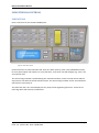
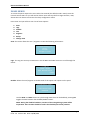
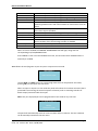
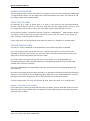
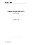
EXPro Installation Manual USER MANUAL, MAINTENANCE GUIDE & LOG BOOK Approved Document No: GLT-212-7-2 Issue: 1.0 Author: MF Date: 19/08/2013 Page 1 EXPro Installation Manual Contents INTRODUCTION ....................................................................................................................................... 3 INDICATIONS & CONTROLS ..................................................................................................................... 4 INDICATIONS ....................................................................................................................................... 4 CONTROLS ........................................................................................................................................... 6 PANEL MENUS......................................................................................................................................... 7 PANEL OPERATION ................................................................................................................................ 10 NORMAL OPERATION ....................................................................................................................... 10 FIRE ALARM CONDITION .................................................................................................................. 10 WHAT TO DO IN THE EVENT OF A FIRE. ....................................................................................... 10 RESETTING FROM AN ALARM CONDITION .................................................................................. 10 MANUAL EVACUATION ..................................................................................................................... 11 FIRST STAGE ALARM ......................................................................................................................... 11 SECOND STAGE ALARM .................................................................................................................... 11 ABORT A SECOND STAGE ALARM ............................................................................................... 11 MANUAL MODE ................................................................................................................................ 12 RESET ............................................................................................................................................... 12 FAULTS ............................................................................................................................................. 12 LOG BOOK ............................................................................................................................................. 13 MAINTENANCE WORK ...................................................................................................................... 13 FALSE ALARMS .................................................................................................................................. 14 ALL OTHER EVENTS ........................................................................................................................... 15 Approved Document No: GLT-212-7-2 Issue: 1.0 Author: MF Date: 19/08/2013 Page 2 EXPro Installation Manual INTRODUCTION The Premier EXPRO is a 2 zone, 1 area extinguishing panel. It has 2 zones dedicated to the extinguishing section. These are known as crossed or co-incidence zones. Both circuits will need to be triggered in order to activate the extinguishing circuit. This kind of operation also referred to as “double – knock” The Extinguishing section is designed to BS EN 12094-1:2003. The panel has an integral Manual Release switch fitted to the front of the panel. The panel has monitored inputs for field connections, such as manual release, abort, etc. The panel has relay outputs for first & second stage alarms, fault, gas fired, and EXT for extract fan. The panel has an add-on board that provides relay outputs for Auto, Manual, and Abort The Premier EXPRO can be in any of the following conditions: Quiescent condition – i.e. System Normal Fault condition Disabled condition Test condition Pre-activated condition The Premier EXPRO will enter the pre-activated condition (first stage alarm) within 1 second of a detector on one of the crossed zones signalling an alarm Activated condition The Premier EXPRO will enter the activated (second stage alarm) condition within 1 second of the second crossed zone signalling an alarm. Released condition The Premier EXPRO will enter the released condition (bottle output activated) within 1 second of establishing the activated condition, or after the delay configured in the bottle output timer WARNING: Access to live components inside this fire alarm enclosure. Only authorised personnel should have access to the inside of the control panel. Approved Document No: GLT-212-7-2 Issue: 1.0 Author: MF Date: 19/08/2013 Page 3 EXPro Installation Manual INDICATIONS & CONTROLS INDICATIONS Here is the fascia for the Premier EXPRO panel. Figure 1. EXPro fascia layout Each function has its own indication LED. There are Alarm (Active), Fault, Test & Disablement LEDs for most panel inputs and outputs. For most functions, more than one LED will light (e.g. zone 1 fire and common fire) The second stage sounder is pulsed during the activated condition, and its sounder active LED will also pulse in time with the actual sounder output. The second stage sounder and its associated LED will switch to constantly on. The panel also has a 20 x 4 LCD display for easy setup of the engineering functions. It also has an event log which will store up to 100 events. Approved Document No: GLT-212-7-2 Issue: 1.0 Author: MF Date: 19/08/2013 Page 4 EXPro Installation Manual The EXPRO has the following LED indicators:General indication LED Power Common Fire Colour Green Red Common Fault Yellow General Disablement Yellow General Test System Fault Yellow Yellow Crossed Zone LED Fire (zone 1) Colour Red Fire (zone 2) Red FLT / Test / Disable Yellow Alarm indications LED Active 1st Stage Alarm Colour Red Active 2nd Stage Alarm Red 1st Stage FLT/TEST/DIABLED Yellow 2nd Stage FLT/TEST/DISABLED Yellow Release Status Manual Mode Auto Mode Abort Colour Yellow Green Yellow Released Red Activated Red Pre-Activated Red Manual Release Red Flooding Zone FLT Yellow Gas Release Counter More Data Colour Yellow Approved Document No: GLT-212-7-2 Issue: 1.0 Author: MF Date: 19/08/2013 Function / Meaning Power healthy Indicates when the panel is in an alarm condition Indicates when the panel is in a fault condition Indicates when an Input or Output has been disabled Indicates when a zone is in test Indicates when there is a processor fault Function / Meaning Indicates when zone 1 is in alarm Indicates when zone 1 is in alarm Indicates when a zone has a fault or in test or disable mode Function / Meaning Indicates when zone 1 or zone 2 is in an alarm condition Indicates when zone 1 or zone 2 is in an alarm condition Indicates 1st stage status when lit Indicates 2nd stage status when lit Function / Meaning Indicates manual release mode Indicates Automatic mode Indicates the release has been aborted Indicates the gas has been released Indicates when both 1st and 2nd stage zones are in alarm Indicates when there is a first stage alarm Indicates when the Manual release switch has been activated Indicates when there is a fault state in the flooding zone Function / Meaning Indicates when there is more than one message to be displayed on the LCD Page 5 EXPro Installation Manual CONTROLS Label Start 1st Stage Sounders Stop 1st Stage Sounders Silence Buzzer Reset Reset CIE LED Test Use Used to start the 1st stage sounders Used to silence the 1st stage sounders Used to silence the internal buzzer in a fault or alarm condition Used to reset the fire detection zone Used to reset the control panel Used to test all panel LED’s Note that the controls can only be used after the code has been entered and the CONTROLS ENABLED (LED) is ON. Approved Document No: GLT-212-7-2 Issue: 1.0 Author: MF Date: 19/08/2013 Page 6 EXPro Installation Manual PANEL MENUS To access the panel requires the user code to be entered (the default code is 2222). Once the Controls Active LED is on you will now be able to start and stop the first stage sounders, reset, silence the inter buzzer and access the relays configuration menu. Press enter and you will then see a list of menu options: 1. 2. 3. 4. 5. 6. 7. Zone Logs Disable Test Engineer Relays Change Time Zone: This menu allows the user / engineer to view the following information: *** Zone Viewing *** Zone 1 Normal Voltage Lvl: 17.3v Logs: The Log can store up to 100 events. Use the NEXT and PREV buttons to scroll through the events. *** LOG *** 12:00 05/02 Man. Release Active 01/95 Disable: Allows the user/engineer to disable each of the inputs and outputs on the panel *DISABLEMENT MENU * Low Pressure input ENABLED Use the NEXT and PREV button to cycle through items that can be disabled, pressing OK toggles the item between the enabled/disabled states: NOTE: During the disabled condition, sections of the extinguishing system will be inoperative. Extra caution should be used in the disabled part of the premises. Approved Document No: GLT-212-7-2 Issue: 1.0 Author: MF Date: 19/08/2013 Page 7 EXPro Installation Manual Zone 1 Zone 2 Gas Fired input Manual release Auto Manual Abort Input Low Pressure Input Sounder 1A Sounder 1B Sounder 2 Bottle Output External Fan Prevents the panel from responding to an alarm in zone 1 Prevents the panel from responding to an alarm in zone 2 Prevents the panel from responding to the gas fired signal Prevents the panel from responding to a manual release Prevents the external switching between auto and manual mode. Switching between auto and manual mode can still be done from the panel. Disables the Abort input. The panel will not enter the alarm condition if the abort input is disabled. Prevents the panel from responding to a low pressure signal. Disables sounder 1A Disables sounder 1B Disables the second stage sounder. The panel will not enter the alarm condition if the second stage sounder is disabled. Disables the bottle output. Disables the output to the external fan When an item is disabled the GENERAL DISABLEMENT LED will light, along with the corresponding FLT/TEST/DISABLED LED. Press CANCEL to exit out of the disablement menu, the item will remain disabled until it is manually re-enabled. Test: Allows the user/engineer to put an input or output into test mode. *TEST MENU * Low Pressure input Use the NEXT and PREV button to cycle through items that can be placed in test mode, pressing OK puts the input into test mode. When an input or output is in test mode the panel will indicate if it has been activated, but is prevented from entering the normal sequence of events (such as activating sounders or bottle output) associated with that input. Note: Only one input/output can be programmed in test mode at any one time. *** Zone In Test *** Zone 1 Time Left: 15:00 The panel will automatically exit from a test condition after 15 minutes. The test condition can be manually exited from the test menu. Approved Document No: GLT-212-7-2 Issue: 1.0 Author: MF Date: 19/08/2013 Page 8 EXPro Installation Manual Change Time: Allows the user / engineer to set the system clock. SET UP TIME 12:00 Approved Document No: GLT-212-7-2 Issue: 1.0 Author: MF Date: 19/08/2013 Page 9 EXPro Installation Manual PANEL OPERATION NORMAL OPERATION With the controls inactive, under normal conditions the system will be silent and the green “POWER LED” illuminated. The LCD will display “SYSTEM NORMAL” The system may either be in “Automatic” or “Manual” mode of operation. This will be evident by the illumination of either the “Automatic” or Manual” LED. In Manual Mode, the bottle output will not be activated automatically. It must be started manually by pressing a manual release call point. FIRE ALARM CONDITION The Premier EXPro signals an alarm by the following: Turn on the General Fire LED Turn on the Zonal Fire Indicator Turn on internal buzzer Start any sounders connected to the panels sounder circuits Activate the First Stage (fire) relay. (Note that the first stage repeater output will not activate. This only operates on an alarm from one of the crossed zones) WHAT TO DO IN THE EVENT OF A FIRE. 1. Follow the building evacuation procedure, and check that everyone has left the building safely. 2. The building fire officer or suitably trained responsible person should CAREFULLY enter the building, and locate the area of the alarm from the fire alarm panel. 3. Investigate to determine the cause of the alarm. Look for the detector in the zone in alarm that signalled the fire. The detector that signalled an alarm will have its RED ALARM LED on. 4. If a small fire is found, a suitably trained person could tackle this with a suitable fire extinguisher. 5. If a larger fire is found, leave the building immediately, and contact the fire brigade. 6. If no fire is found, make a note of the detector that signalled fire, and look for anything nearby that could be the cause of the activation, eg cooking, or use of a hot air gun etc. 7. Record findings in the fire alarm log book. RESETTING FROM AN ALARM CONDITION After the relevant action has been taken, the Premier EXPro fire alarm panel can be reset by the following:1. 2. 3. 4. Gain user access to the panel by entering the password (default 2222) Press Start/Stop 1st Stage Sounder button, this will silence the external sounders. Press Silence Buzzer button. This will silence the panel`s internal buzzer. Press the Reset button. This will return the panel to its normal condition. If the panel goes straight back into alarm, then the cause of the alarm has not been cleared. This could be a detector still exposed to smoke, or a call point still in the active position. Investigate for a call point, or detector that still has its RED ALARM LED on. Reset the call point, or clear the smoke. If the problem persists, contact an engineer. Approved Document No: GLT-212-7-2 Issue: 1.0 Author: MF Date: 19/08/2013 Page 10 EXPro Installation Manual MANUAL EVACUATION The first stage sounders can be started by activating the controls and pressing the START/STOP 1st Stage Sounder Button. The first stage relay is NOT operated by this action. The common fire & first stage sounder active LEDs will light. FIRST STAGE ALARM On detection of a “FIRE” in either Zone 1 or Zone 2, the zone fire LED will be illuminated and the internal buzzer will be on. The first stage LED and first stage sounder will be on. The first stage relay output will be active. The first stage repeat output will also be active. To silence the sounder, activate the controls, and press S TART/STOP 1st Stage Sounder Button. The panel’s internal tone and fire LEDs will remain active until the cause of the alarm has been removed, and the panel has been reset A first stage alarm can be silenced & reset when the panel is in automatic or manual mode. SECOND STAGE ALARM As soon as a “FIRE” is detected in the second Zone, the second stage alarm is initiated. The second stage sounder will be pulsed on for 1 second, then off for 1 second. This will be repeated as the timer counts down. The two-zone alarm LEDs will be illuminated as well as first stage alarm, second stage alarm and Activated LEDs. The second stage cannot be silenced and after a delay period, (user programmable) the extinguishing output will be initiated releasing the extinguishing agent, and the second stage sounder will now be on constantly. This will be followed by the “GAS FIRED” indication, indicating that the extinguishing agent has been released. Once the second stage alarm has been initiated, it is advisable to evacuate and Seal the protected area prior to the release of the extinguishing agent. Operation of the “Manual Release” call point will initiate the second stage alarm. Lift the flap and push the switch up to activate. A second stage alarm can only be silenced & reset when the panel is in manual mode. ABORT A SECOND STAGE ALARM If the abort input is used, the panel will abort the gas release, and the panel will need to be reset. Note that after the pre-release timer has finished, and the bottle output has activated, the abort input will have no effect. Approved Document No: GLT-212-7-2 Issue: 1.0 Author: MF Date: 19/08/2013 Page 11 EXPro Installation Manual MANUAL MODE In this mode operation, Zone Fire and Fault alarms are still in operation, and first & second stage sounders will operate, but the bottle output to the extinguishing agent will not operate. RESET To reset panel from a first stage alarm condition, activate the controls and press START/STOP SOUNDERS, followed by SILENCE BUZZER, then RESET. If the panel enters the second stage alarm (while in automatic mode), the panel cannot be reset until the bottle output has operated, and the reset inhibit timer has ended. The panel can NOT be reset from a fault condition. All faults are non latching, so when a fault clears from the panel it will be automatically cleared from the display. In the event of an alarm in the peripheral fire zones & crossed extinguishing zones simultaneously, the reset button can be used to reset the peripheral zones, but won`t have an effect on the extinguishing zones until the reset inhibit timer has ended. FAULTS When a fault is detected the relevant LED will illuminate and the buzzer will sound. The LCD will display details of the fault(s) and show each detected fault in turn. Enable the controls and press the Silence Buzzer button to silence the panel. Press the NEXT and PREV buttons to manually cycle through the list of faults, the display will show the number of faults in the lower right corner. *** DEVICE FAULT *** BOTTLE OUTPUT O/C 01/03 Approved Document No: GLT-212-7-2 Issue: 1.0 Author: MF Date: 19/08/2013 Page 12 EXPro Installation Manual LOG BOOK MAINTENANCE WORK DATE TIME ZONE/LOCATION REASON FOR WORK Approved Document No: GLT-212-7-2 Issue: 1.0 Author: MF Date: 19/08/2013 WORK CARRIED OUT ADDITIONAL WORK REQUIRED SIGNED Page 13 EXPro Installation Manual FALSE ALARMS DATE TIME ZONE/ LOCATION CAUSE (IF KNOWN) OR ACTIVITIES IN ALARM AREA MAINTENANCE VISIT NEDED (YES/NO) Approved Document No: GLT-212-7-2 Issue: 1.0 Author: MF Date: 19/08/2013 MAINTENANCE FINDINGS CATEGORY OF FALSE ALARM FURTHER ACTION REQUIRED SIGNED Page 14 EXPro Installation Manual ALL OTHER EVENTS DATE TIME ZONE/ LOCATION DETAILS OF EVENT (INCLUDING CAUSE IF KNOWN) Approved Document No: GLT-212-7-2 Issue: 1.0 Author: MF Date: 19/08/2013 ACTION REQUIRED DATE COMPLETED INITIALS Page 15