1
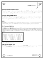
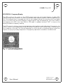
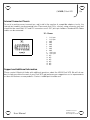
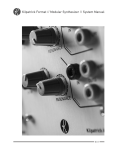
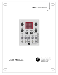
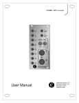
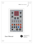
// K3020 // Dual VCO
User Manual
Hardware Version E
October 26, 2010
Kilpatrick Audio
// K3020 // Dual VCO
2p
Introduction
The K3200 Dual VCO is a state-of-the-art dual analog voltage controlled oscillator that is both
musically and technically superb. The design is optimized for great sound and playability for both
tonal and experimental music. Both channels also function as excellent LFOs capable of generating
interesting modulating voltages. Dual independent power supplies provide clean power separately to
each channel for improved stability. Each VCO core is comprised of a monolithic VCO chip which
provides sine, triangle and ramp waves with excellent linearity and low distortion and high-end
matched transistors are used for good CV volt/octave tracking. Internal factory-trimmed adjustments
are provided for CV volt/octave and high tracking on each channel.
By offering waveform and mode adjustments through computer-controlled analog signal routing as
well as internal VCA-based mixing circuits, noise-free switching and blending between waveforms is
possible. All modes are shown with LEDs on the front panel, and the current frequency of each VCO is
displayed on an LCD readout. The use of computer control over the signal routing means that audio
signals never pass through the front panel.
Inputs are provided on each channel for CV (volt/octave) and FM tuning inputs, PWM and blend CV
inputs for driving the wave shaping stages, and a sync input for hard sync effects. Outputs are
provided for both the blend circuit output as well as a dedicated pulse output of only the PWM and
pulse shaping sections. Two special outputs are provided that contain signals from both channels. The
wave mix output offers only the wave signals from each channel, and the XOR output provides a digital
multiplication of both channels which works similar to a ring modulator, but outputs square waves.
In addition to offering two very capable independent VCOs, the cross modulation section allows
control of VCO2 from VCO1. Cross mod controls allow pitch, PWM and blend mixing modulation, and
the internal PLL and SYNC circuits allow the VCO2 oscillator to be controlled by VCO1 in a variety of
different ways without requiring external patch cables. With only an audio output cable attached, an
enormous variety of experimental sound possibilities exist. As part of a complete modular system the
possibilities are virtually endless.
This manual will help to explain the layout of the controls and various features of the VCO. The world
of the K3020 is yours to discover and there are a lot of subtle effects that can not possibly be explained
in the manual. We hope that the K3020 will bring you a lifetime of enjoyment and sonic exploration.
Features
•
•
•
•
Eurorack (3U) form factor - 36HP width
Dual VCO with independent power supplies per channel
Backlit LCD screen with frequency counter for each channel
LED indication of selected switch positions and VCO core activity
•
Each channel:
◦ 1V/octave CV input – factory trimmed for 1V/octave response
User Manual
Hardware Version E
October 26, 2010
© 2010 Kilpatrick Audio
// K3020 // Dual VCO
◦
◦
◦
◦
◦
◦
◦
◦
◦
◦
◦
3p
Linear FM input with level control
Fine and coarse tuning controls
Normal VCO frequency range: 2Hz to 15kHz
LFO mode switch – period: greater than 70 seconds to 8ms (120Hz)
Temperature compensated exponential converter with super-matched transistors
Wave shaper with sine, triangle or ramp waveforms – switch selectable
Pulse shaper with three pulse types – switch selectable
Voltage controlled mixing between wave and pulse waveforms
High-end blend VCAs with ultra-low distortion and linear control
Sync input for hard syncing of VCO core
PWM input with level and offset controls – full deflection with 5Vpk-pk
•
◦ Blend VCA control input with level and offset controls – full deflection with 5Vpk-pk
◦ Blend output – output from the blend VCA containing wave and/or pulse waveforms
◦ Pulse output – dedicated output from the pulse shaper containing pulse waveform
Internal cross modulation for modulating VCO2 from VCO1:
◦ Pitch modulation control – exponential frequency modulation of VCO2 from VCO1
◦ PWM modulation control – modulate VCO2 pulse width from VCO1
◦ Blend modulation control – blend between WAVE and PULSE waves on VCO2 from VCO1
◦ Internal PLL mode for locking VCO2 to VCO1
◦ Internal Sync mode for syncing VCO2 to VCO1
Wave mix output – buffered mix of VCO1 and VCO2 wave outputs – for FM effects
XOR output – digital Exclusive OR output from both VCOs – for ring mod-like effects
All inputs and outputs are tolerant of +/-12V
All outputs drive 10Vp-p with 1K output impedance
Requires +12V (200mA), -12V (100mA) - 16 pin Doepfer-style power cable used – approx.
3.5W total power consumption
Designed and made in Canada using high quality parts.
•
Warranty: 1 year
•
•
•
•
•
•
User Manual
Hardware Version E
October 26, 2010
© 2010 Kilpatrick Audio
// K3020 // Dual VCO
4p
Analog and Digital
The K3020 contains both analog and digital circuitry but rest assured that the VCOs are purely analog,
and purely DC coupled throughout the entire signal path. Full range, dedicated control and audio signal
paths are present through the entire oscillator. The front panel switches and frequency counter are
computer-controlled for accuracy. This ensures that audio signals are not passed through the front
panel switches, preserving the signal integrity and providing noise-free mode switching. We believe that
this approach offers the best of both worlds regarding usability and signal purity.
Installation and Setup
When installing the K3020 in your modular system, pay close attention to the pinout and direction of
the 16-pin power input cable. The K3020 contains protection against reverse connection, but please
double-check the cable before switching on the unit. The warranty does not cover damage caused by
wrong installation or incorrect / missing power supplies!
Be sure to mount the module in your system using all four screw holes. Do not operate the unit if not
mounted in a proper Eurorack enclosure. Calibration procedures should only be carried out by
qualified persons. If you require assistance, please call your dealer or contact Kilpatrick Audio at:
[email protected] and we would be pleased to help you.
First Use
The first thing you should do when installing the K3020 is to simply attach an output cable to one of
the oscillators. Start by plugging into the BLEND OUT jack on one oscillator. Make sure that the PITCH
MOD, PWM MOD and BLEND MOD controls are turned down, the PLL/SYNC switch is set to the middle
position and the LFO switches are off. By adjusting the FINE TUNE and COARSE TUNE controls, you
should be able to hear sound right away. Experiment with the WAVE and PULSE type controls as well
as the BLEND OFFSET control. The PWM OFFSET control should be near the middle of its range.
To hear both channels at once, plug into the WAVE MIX OUT jack. Note that this signal contains the
outputs from the wave shapers for both channels. The blend circuit has no effect. For more wild
sounds try the XOR OUT jack to hear a digital exclusive OR (phase comparison) of both channels. This
will give ring modulator type of effects.
By connecting to the BLEND OUT jack of VCO2 you can check out the cross modulation capabilities of
the K3020. Although most of these effects are possible with the use of patch cords, by using the builtin controls you can access a wide range of sounds without patching anything. Note that the signal
used by the cross modulation controls is derived from the BLEND OUT signal on VCO1.
User Manual
Hardware Version E
October 26, 2010
© 2010 Kilpatrick Audio
// K3020 // Dual VCO
5p
Note about Included Waveform Images
The waveform images in this manual are produced from actual K3020 recordings. Some loss of detail is
evident, especially for pulse-type waveforms. This is due to limitations of digital sampling. All
waveforms were sampled by a Yamaha 01v mixer and transfered to a computer digitally.
Oscillator Features and Controls
The K3020 Dual VCO contains two identical oscillators, a cross modulation section consisting of
controls which are used to control VCO2 from VCO1, a frequency counter display, as well as outputs
which contain signals from both oscillators at the same time.
CV IN
The CV IN jack on each VCO is factory calibrated for 1V/octave response. It is the main tuning input to be
used for melodic playing from a MIDI to CV converter, volt/octave keyboard, sequencer and so on.
FM - Frequency Modulation
The FM IN jack and FM LEVEL control on each VCO is used to linearly frequency modulate the oscillator
frequency. The FM LEVEL control affects the modulation depth based on the input voltage. Note that the
amount of frequency change in Hz depends on the current frequency set by the CV IN jack and tuning
controls.
Fig. 1 – Frequency Modulation
FINE TUNE and COARSE TUNE
Each VCO has both fine and coarse tuning controls. FINE TUNE operates over a range of about 8
semitones. COARSE TUNE operates over the entire frequency range of the oscillator.
User Manual
Hardware Version E
October 26, 2010
© 2010 Kilpatrick Audio
// K3020 // Dual VCO
6p
LFO Switch - Low Frequency Oscillator
The LFO switch puts the oscillator into LFO (Low Frequency Oscillator) mode. All other controls and
inputs work identically when in LFO mode except that the frequency range of the waveforms is altered.
Note that LFO mode is designed for frequencies below the audio range, however it is possible to
modulate up into low bass frequencies. The maximum period is more than 70 seconds. The LED beside
the LFO switch is lit when LFO mode is enabled.
WAVE – Waveform Selection
The WAVE switch is used to select the primary waveform for the oscillator. Sine, Triangle and Ramp
waves are possible. The LEDs beside the WAVE switch indicate the currently selected wave.
Fig. 2 – Sine Mode
Fig. 3 – Triangle Mode
Fig. 4 – Ramp Mode
PULSE – Pulse Selection
The pulse section takes the currently selected wave as its input and produces a pulse output using three
PWM circuits plus combining circuitry on each channel. The PWM controls affect the pulse output. (see
below) The PULSE switch selects one of three different pulse output types. Either a single, dual or multipulse output can be selected. The dual and multi-pulse modes have the effect of adding additional
transitions to the waveform during each cycle. This creates interesting timbres and harmonics which
can be modulated with the PWM controls. The LEDs next to the PULSE switch indicate the currently
selected pulse mode.
Fig. 5 – Single Pulse Mode
User Manual
Fig. 6 – Dual Pulse Mode
Fig. 7 – Multi-pulse Mode
Hardware Version E
October 26, 2010
© 2010 Kilpatrick Audio
// K3020 // Dual VCO
7p
PWM – Pulse Width Modulation
The PWM IN jack is used to externally modulate the pulse width of the pulse section. The PWM LEVEL
control affects the sensitivity of this input, and the PWM OFFSET control affects the default PWM setting
when no external voltage is applied. If the pulse section produces no output, adjust the PWM OFFSET
control.
The PULSE OUT jack outputs the result of the PWM and pulse shaping circuitry.
BLEND – Wave and Pulse Blend Mixing
The outputs from the wave and pulse sections mix together using internal Voltage-Controlled
Amplifiers. (VCAs) This allows voltage control over the timbre of the waveform by allowing any mixture
from fully wave to fully pulse to be selected. The BLEND IN jack is used to adjust the blend mixture with
a voltage. the BLEND LEVEL control affects the sensitivity of the input and the BLEND OFFSET adjusts
the default blend setting when no external voltage is applied.
The BLEND OUT jack is the main output from the blend circuit.
Fig. 8 – Blend Mixing – Triangle and Pulse
User Manual
Hardware Version E
October 26, 2010
© 2010 Kilpatrick Audio
// K3020 // Dual VCO
8p
Master and Cross Modulation Features and Controls
PITCH MOD – VCO1 to VCO2 Pitch Modulation
The PITCH MOD control can be used to modulate the frequency of VCO2 from VCO1. The response is
exponential. The effect can be varied from subtle vibrato to full-range frequency sweeps. The BLEND
OUT signal from VCO1 is used as the input to the PITCH MOD control.
PWM MOD – VCO1 to VCO2 Pulse Width Modulation
The PWM MOD control can be used to modulate the PWM circuit of VCO2 from VCO1. The BLEND OUT
signal from VCO1 is used as the input to the PWM MOD control.
BLEND MOD – VCO1 to VCO2 Blend Modulation
The BLEND MOD control can be used to modulate the blend setting of VCO2 from VCO1. The BLEND OUT
signal from VCO1 is used as the input to the BLEND MOD control.
PLL / SYNC Switch
The PLL / SYNC switch is used to select either the PLL or SYNC modes which affect VCO2. The LEDs
light to indicate which mode is active. If the switch is set to the middle position neither mode is
activated. See below for descriptions of each mode.
PLL Mode
When PLL mode is enabled, VCO2 will be fed a tuning voltage that is proportional to the difference in
phase between VCO1 and VCO2. If the frequencies of both oscillators are sufficiently close together they
will lock into phase. This can be used for interesting effects. It is also possible to lock the oscillators to
harmonic intervals of each other. The PLL mode does not offer tracking control and is designed for fast
locking and tight tracking.
By inputting a control voltage to both VCO1 and VCO2 CV IN jacks simultaneously it is possible to ensure
both oscillators are perfectly in tune for creating timbres that combine the waveforms of both
oscillators.
SYNC Mode
When SYNC mode is enabled, VCO2 will be hard synced to VCO1. This can be used for making very
powerful sounds when both inputs are fed with the same tuning voltage, and all kinds of strange
harmonically-rich timbres if the tuning on one oscillator is adjusted when SYNC is engaged.
User Manual
Hardware Version E
October 26, 2010
© 2010 Kilpatrick Audio
// K3020 // Dual VCO
9p
WAVE MIX OUT
WAVE MIX OUT produces a mixture the waveshaper outputs of both VCO1 and VCO2. These signals are
derived before the blend VCA circuits. This allows the BLEND and PULSE outputs of each VCO to
generate other types of waveforms while offering an additional mix output of the basic waveforms
from each VCOs.
Fig. 9 - Wave Mix – Sine Waves on VCO1 and VCO2
XOR OUT
The XOR OUT is a digital exclusive-OR mixture of both VCOs. This signal is derived from an internal
square-wave signal from each VCO. XOR produces sound similar to ring modulation, although the sound
contains many more harmonics because the signal is made up of square waves.
Fig. 10 - XOR Out – VCO1 and VCO2 at Unrelated Frequencies
User Manual
Hardware Version E
October 26, 2010
© 2010 Kilpatrick Audio
// K3020 // Dual VCO
10p
VCO STATUS - Frequency Display
The LCD screen in the centre of the K3020 panel shows the measured frequency of both VCOs
simultaneously. Measurements are taken by two dedicated frequency counters and are updated every
0.5s. The reading shown is averaged over the last two readings, giving 1Hz resolution which has better
than 1% accuracy over the entire frequency range except for very low frequencies. (less than 100Hz) If
the frequency of a VCO is less than 30Hz or LFO mode is enabled, the word "LFO" is shown on the
display instead of a frequency reading.
The LCD contrast is factory set at room temperature and should not need adjustment. If necessary, the
contrast control can be adjusted by using a #1 philips screwdriver with a narrow shaft. Carefully insert
the screwdriver in the hole. The contrast adjustment is on the internal circuit board. Be very careful not
to press on or pry any nearby components. A high quality adjustment screwdriver should be used.
User Manual
Hardware Version E
October 26, 2010
© 2010 Kilpatrick Audio
// K3020 // Dual VCO
11p
VCO Calibration
The K3020 is factory calibrated and under most circumstances you should not need to make
adjustments. However if you have problems with scale tuning or ramp wave linearity you may need to
make adjustments. We recommend that adjustments only be done by qualified persons. If you feel
uncomfortable making these adjustments, contact us or ask a qualified friend or dealer to help you.
Each VCO has three multi-turn trim pots:
•
V/Octave Scale Adjustment – Adjusts the VCO core for precise 1V = 1 octave scaling
•
V/Octave High Track – Adjusts the VCO core for high frequency tuning compensation
•
Ramp Symmetry – Adjusts the ramp shaper symmetry for minimal distortion
VCO1 Calibration Trim Pots
•
•
•
R13 – VCO1 V/Octave
R17 – VCO1 High Track
R44 – VCO1 Ramp Symmetry
VCO2 Calibration Trim Pots
•
•
•
R103 – VCO2 V/Octave
R107 – VCO2 High Track
R60 – VCO2 Ramp Symmetry
V/Octave Adjustment
When adjusting the V/octave tracking, start by turning the High Track control completely counter
clockwise. Normally the high track is barely needed. Adjust the V/octave tracking with the oscillator
tuning controls near their centre positions. Achieve good linearity over the normal music pitch range
(25-4000Hz or so) and only apply high track adjustment if the very high frequencies (4000-8000Hz) are
flat. Recheck the entire tuning range after making final adjustments.
Ramp Symmetry Adjustment
The ramp waveform is generated by two halves of a triangle wave. The centre of the ramp slope can be
adjusted to produce a linear ramp without any bumps in the response. This adjustment normally
requires an oscilloscope to make correct adjustments. If you lack an oscilloscope, use the VCO in LFO
mode to module the CV of another oscillator and only select the ramp waveform as the output. You
should hear smooth frequency sweeps without any change in sweep speed. This is very easy to detect
and tune by ear.
User Manual
Hardware Version E
October 26, 2010
© 2010 Kilpatrick Audio
// K3020 // Dual VCO
12p
Internal Connector Pinouts
To assist in making correct connections, and to aid in the creation of compatible adaptor circuits, the
internal pin headers are documented here. Please note that X18 is a factory setup connector only and
should not be used. Both X11 and X12 connectors are 0.100" pitch pin headers. Standard IDC ribbon
cables can be connected.
X1 – Power:
1.
2.
3.
4.
5.
6.
7.
8.
9.
10.
11.
12.
13.
14.
15.
16.
-12V input
-12V input
GND
GND
GND
GND
GND
GND
+12V input
+12V input
N/C
N/C
N/C
N/C
N/C
N/C
Support and Additional Information
Please contact Kilpatrick Audio with additional questions about the K3020 Dual VCO. We will do our
best to help you make the most of your Dual VCO and welcome your suggestions as to improvements
or ideas for features on new products. Contact: [email protected]
User Manual
Hardware Version E
October 26, 2010
© 2010 Kilpatrick Audio