1
Mixrate-X20
USER’S MANUAL
Manual code MAN-053 – Revision 04
Revision date: 05 23, 2008
MIX-Rate X20 – USER'S MANUAL
Pag 2/34
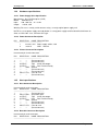
Vital Diagnostics
Vital Diagnostics
MIX-Rate X20 – USER'S MANUAL
CONTENTS
1.
INTRODUCTION .............................................................................................................................6
1.1
1.2
OPERATOR QUALIFICATION .........................................................................................................6
ANALYTICAL RESULTS ................................................................................................................6
2.
INTENDED USE..............................................................................................................................7
3.
IMPROPER USE .............................................................................................................................7
4.
INSTALLATION ..............................................................................................................................7
4.1
4.2
4.3
4.4
5.
PLACEMENT OF THE ANALYZER ...................................................................................................7
CONFIGURATION........................................................................................................................7
POWER ON ...............................................................................................................................7
SETUP: MAIN MENU - FUNCTION (6) ...........................................................................................8
FUNCTIONS ...................................................................................................................................9
5.1
MAIN MENU FUNCTION (1) ID: SAMPLES IDENTIFICATION ...............................................................9
5.1.1 Samples Identification: Sub-Menu Function (1) ID1 ........................................................... 10
5.1.2 Samples Identification: Sub Menu Function (2) ID2............................................................ 11
5.2
MEMORY: MAIN MENU FUNCTION (2) MEM ............................................................................... 11
5.2.1 Memory: Sub-Menu Function (1) Clear .............................................................................. 11
5.2.2 Memory: Sub-Menu Function (2) Edit ................................................................................ 12
5.3
QUALITY CONTROL: MAIN MENU FUNCTION (3) QC ..................................................................... 12
5.3.1 QC INP: Sub-Menu Function (2)........................................................................................ 13
5.3.2 QC ID: Sub-Menu Function (1) .......................................................................................... 13
5.3.3 QC CH: Sub-Menu Function (4) ........................................................................................ 14
5.3.4 QC ED: Sub-Menu Function (3)......................................................................................... 14
5.3.5 QC PRT: Sub-Menu Function (5) ...................................................................................... 15
5.3.6 QC DEL: Sub-Menu Function (6)....................................................................................... 15
5.4
PRINTOUT: FUNCTION (4) PRINT ............................................................................................... 15
5.4.1 W.List: Sub-Menu Function (1) .......................................................................................... 15
5.4.2 Memory: Sub-Menu Function (2) ....................................................................................... 15
5.4.3 Memory Range: Sub-Menu Function (3) ............................................................................ 15
5.5
HOST: FUNCTION (5) HOST....................................................................................................... 16
6.
SYSTEM DESCRIPTION .............................................................................................................. 16
6.1
6.2
6.3
6.4
6.5
7.
OPERATING PROCEDURE.......................................................................................................... 17
7.1
7.2
7.3
7.4
7.5
7.6
7.7
8.
MIXRATE-X20 ANALYZER.......................................................................................................... 16
RESULTS IN 15 MINUTES ........................................................................................................... 16
SYMBOL DESCRIPTION ............................................................................................................. 16
SEDIMENTATION GRAPH............................................................................................................ 17
ESR TUBES ............................................................................................................................ 17
SAMPLE COLLECTION ............................................................................................................... 17
LABELING................................................................................................................................ 17
SAMPLE INSERTION BATCH MIXING MODE .................................................................................... 18
SAMPLE INSERTION IN RANDOM MODE ........................................................................................ 18
SAMPLE REMOVAL.................................................................................................................... 18
FINAL RESULTS ....................................................................................................................... 18
BRIEF W ORKING INSTRUCTIONS ................................................................................................ 19
SAFETY MEASURES ................................................................................................................... 19
8.1
8.2
8.3
8.4
8.5
USER PRECAUTIONS ................................................................................................................ 19
ELECTRICAL EQUIPMENT ........................................................................................................... 19
MECHANICAL EQUIPMENT.......................................................................................................... 19
SAMPLES ANALYSIS ................................................................................................................. 19
NOTES ON SAFETY MEASURES ................................................................................................... 20
Pag 3/34
MIX-Rate X20 – USER'S MANUAL
8.6
9.
Vital Diagnostics
RESIDUAL RISKS ..................................................................................................................... 20
PERFORMANCE CRITERIA AND LIMITATIONS ......................................................................... 21
9.1
9.2
10.
PERFORMANCE CRITERIA ......................................................................................................... 21
LIMITATIONS ........................................................................................................................... 21
TEMPERATURE COMPENSATION ......................................................................................... 21
10.1
11.
RESULTS CORRECTION TO 18°C ............................................................................................... 21
MAINTENANCE........................................................................................................................ 22
11.1
11.2
12.
MAINTENANCE ........................................................................................................................ 22
CLEANING INSTRUCTIONS ......................................................................................................... 22
ERROR DISPLAYS .................................................................................................................. 22
12.1
12.2
12.3
12.4
12.5
RESULT DATA ERROR .............................................................................................................. 22
QC DATA ERROR .................................................................................................................... 22
CHECK PRINTER...................................................................................................................... 22
CHECK HOST CONNECTION ...................................................................................................... 22
ERROR: SYSTEM STOPPED....................................................................................................... 22
13.
TROUBLESHOOTING ............................................................................................................. 23
14.
APPENDIX................................................................................................................................ 23
14.1
W ESTERGREN METHOD ........................................................................................................... 23
14.2
REFERENCE RANGES OF NORMAL ESR VALUES ......................................................................... 23
14.3
ESR IN DISEASE STATES .......................................................................................................... 24
14.4
HARDWARE SPECIFICATIONS..................................................................................................... 25
14.4.1
Power Supply Units Specification .................................................................................. 25
14.4.2
Power Connector Description........................................................................................ 25
14.4.3
Printer Connector Description ....................................................................................... 25
14.5
HOST SPECIFICATIONS ............................................................................................................. 25
14.5.1
Host Connector Description .......................................................................................... 25
14.5.2
Barcode Connector Description..................................................................................... 25
14.5.3
Host Connection Specifications - Communications Protocol .......................................... 26
14.5.4
HOST CONNECTOR SIGNALS DESCRIPTION ........................................................... 26
14.5.5
HOST/DATA TRANSMISSION" REQUEST FROM HOST COMPUTER ....................... 26
14.5.6
MESSAGES SENT IN THE BEGINNING ...................................................................... 26
14.5.7
MESSAGE SENT FOR ANY RESULT STORED IN MEMORY ..................................... 27
14.5.8
DESCRIPTION OF THE DATA FRAME........................................................................ 27
14.6
INTERFACING SPECIFICATIONS .................................................................................................. 28
14.6.1
Basic Procedure ........................................................................................................... 28
14.6.2
Configuration ................................................................................................................ 28
14.6.3
Hardware Configuration ................................................................................................ 28
14.6.4
Software Configuration ................................................................................................. 28
14.7
DATA FORMAT & EXAMPLE DATA FILE ......................................................................................... 30
5.4 CHECKSUM CALCULATION ................................................................................................................ 30
15.
INTERNAL BARCODE SCANNER DEFAULT CONFIGURATION ........................................... 31
16.
TECHNICAL SPECIFICATIONS ............................................................................................... 32
17.
EC DECLARATION .................................................................................................................. 33
18.
DISPOSAL AND RECYCLING ................................................................................................. 34
Pag.4 / 34
Vital Diagnostics
MIX-Rate X20 – USER'S MANUAL
Pag.5 / 34
MIX-Rate X20 – USER'S MANUAL
1.
Vital Diagnostics
INTRODUCTION
Prior to operating the Mixrate-X20, carefully read the instructions in this manual for proper use of the
instrument.
Mixrate-X20 has been designed to simplify ESR analysis, avoiding sample handling and reducing the
operator’s risk of infection. To perform the analysis, the operator simply places the sample in the
instrument. The results are complete in 30 minutes, correlated to one (1) hour following the Westergren
reference method. This feature allows the instrument to be used directly on the ward, in the blood sample
collection department and in small laboratories.
Caution! Before installing and working with the Mixrate-X20 analyzer, read this manual
carefully and observe the safety precautions and regulations stated. Safety comes first!
The Mixrate-X20 was designed and manufactured to conform to various national and international
standards and safety regulations. Possible known risks were eliminated or reduced. Nevertheless, all risk
cannot be eliminated. When operating the Mixrate-X20, national guidelines and regulations must be
observed, as in the normal lab routine. Power supply accessories (cables/plugs) must be installed in such
a way that sources of danger (overheating of cables, short circuit due to incorrect fuse ratings, loose
cables etc.) are eliminated. The user should be aware that if the Mixrate-X20 is not used in the manner
specified by the manufacturer, the protection provided by the equipment and the measurement results
may be impaired. This manual should be kept with the instrument for consultation when necessary.
CAUTION
To assure proper instrument performance, Vital Diagnostics requires the use of Vital Diagnostics ESR
Vacuum Tubes or ESR Non-Vacuum Tubes, and Precision-Rate Controls with this analytical system.
This instrument is designed as a system. Results obtained from the system may vary depending upon
the specific characteristics of disposables, controls, and operator expertise. Control kits and the test
parameters for each control have been optimized and tested to ensure compatibility and performance
with the instrument. Vital Diagnostics assumes no responsibility for erroneous test results caused by
disposable tubes or controls not supplied by Vital Diagnostics, or by inappropriate use.
The analyzer and accessories are shipped in transport boxes and should be unpacked and installed using
instructions supplied by Vital Diagnostics. If these instructions are not observed, Vital Diagnostics
assumes no responsibility for consequential damage or improper operation of the analyzer.
1.1
Operator Qualification
The instrument should only be used by qualified and trained personnel. For clinical tests, the instrument
should be used under the management of a doctor or qualified laboratory technician/technologist in
compliance with CLIA and local regulations.
1.2
Analytical Results
The analytical results depend upon not only the correct operation of the analyzer but also a variety of
external influences beyond the control of the manufacturer. Therefore a qualified clinician must carefully
examine the test results obtained with this instrument before any diagnostic or therapeutic measures are
taken based on the analytical results.
Caution! An incorrectly measured result may lead to an error in diagnosis.
Technical Service
Service to the instrument must be performed by local distributor service representative.
provided by other person(s) will invalidate the warranty.
Pag.6 / 34
Service
Vital Diagnostics
2.
MIX-Rate X20 – USER'S MANUAL
INTENDED USE
The MIX-Rate ESR analyzer is an automatic instrument for the analysis of the erythrocyte sedimentation
rate. It constantly and simultaneously scans 10 test tubes which are custom-made for ESR analysis. The
MIX-F follows the sedimentation of each sample independently, memorizing levels for the whole period
of analysis.
3.
IMPROPER USE
Following uses are considered improper:
1) Use of the device to obtain results different from ESR
2) Use tubes different from those specified in this manual
3) Every attempt to open tubes analyzed by the device
4) Use the device to analyze samples different from those specified
5) Every attempt to open the mixing panel when it’s closed, or to block its movement
The above mentioned uses and every attempt to use the MIX-Rate X20 ESR analyzer with a purpose
different from the intended use, must be considered improper.
4.
INSTALLATION
4.1
Placement of the Analyzer
The Mixrate-X20 must not be placed near centrifuges, oscillating agitators or other vibrating instruments
which might cause movement of the bench.
Please keep in mind that the ESR instrument is very sensitive to vibrations, which could cause a false
increase of results.
The workbench must be flat and leveled.
Direct light on the instrument and sudden changes in temperature should be avoided.
4.2
Configuration
Mixrate-X20 will be supplied factory configured.
4.3
Power on
Connect power supply outlet to the instrument.
Insert the power supply plug into the electrical socket.
Once connected, turn on the Mixrate-X20 using the switch situated at the rear side
of the instrument.
Each time the Mixrate-X20 is switched on, it carries out an electronic initialization
and an instrument self-test to check for proper operation.
Pag.7 / 34
MIX-Rate X20 – USER'S MANUAL
Vital Diagnostics
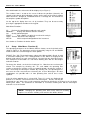
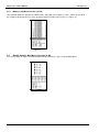
After initialization, the main menu will be displayed (see Figure 1).
The numbers from 1 to 20 on the screen indicate the positions (channels) for
samples to be placed, while indications relative to the status of the analysis appear
above channels 1 through 10, and below channels 11 through 20. See Section 4.3
for complete symbol descriptions.
On the top of the display there are six (6) functions. They can be accessed by
pressing the appropriate number on the keypad.
Main-Menu Functions:
ID:
Register the identification number for each sample
MEMORY
Display and edit data stored in memory
QC:
Quality Control program
PRINT:
Print a work list, or print the results of the analysis
HOST: Transfer data to the host computer
SETUP:
Initial setup and configuration of the instrument
Figure 1
See Section 3, Functions for further details.
4.4
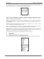
Setup: Main Menu - Function (6)
The operating parameters of the Mixrate-X20 are factory set to the default values
shown in Figure 2. The parameters may be changed by using the UP and DOWN
arrows to move the cursor through the menu options.
RESULT (Res. XX): The default factory setting of the Mixrate-X20 is Result 1h, with
a 30 minute working time. This setting provides results which are displayed and
printed in 30 minutes for each measurement, referenced to one hour Westergren.
The coefficient of correlation at a 30 minute working time with the Westergren
method is R=0.98.
To change the default, set the desired setting to Yes. More than one result may be
chosen. For example, by selecting “30”, “1h”, and “30/60”, the operating time
remains at 30 minutes and the results are reported for both “30 minutes” and for “1
hour” referencing the Westergren method. By selecting “2h”, the operating time is
one hour for each measurement referencing the 2 hour Westergren. All three
combinations are possible with a 2 hour operating time and all three results
reported.
Figure 2
If the 15 minute working time is selected “W. Time: 15”, results are displayed and
printed in 15 minutes, referenced to one hour Westergren. Results can only be
correlated to a one hour value; results cannot be correlated to 30 minutes or 2 hours in the 15 minute
working time mode. The coefficient of correlation at 15 minutes working time with the Westergren
method is less than R=0.92.
NOTE! Changing the operating time with results stored in memory
requires a reset of the memory, and stored results will be deleted.
Pag.8 / 34
Vital Diagnostics
MIX-Rate X20 – USER'S MANUAL
After the operating time has changed, a message will appear indicating that the results stored in memory
will be deleted (see Figure 3). Press [ENT] to accept and [ESC] to abort.
Figure 3
T REF: The Mixrate-X20 features an automatic adjustment of temperature related to the reference
temperature of 18°C in accordance with Manley (see Section 8, Temperature Compensation for further
details). To change this setting, select No.
PRINT: The default printer is an internal printer, as indicated by the “INT”. If you wish to connect an
external printer, select "EXT". Select "NO" if a printer will not be connected, and you do not wish to use
the internal printer.
GRAPH: To view the sedimentation graph (see Section 4.4), set Graph to either Yes or Auto. If Auto is
set, the sedimentation graph will print with each result.
HOST: The instrument may be connected to a Laboratory Information System (LIS). To transfer the
results to a laboratory computer, it is necessary to select YES or AUTO on the HOST line.
DATE and TIME: If needed, register the date and local time by moving the cursor to the desired line and
pressing enter. Use the numeric keypad to enter the numbers. The date format is month/day/year.
Additionally, a 24 hour clock is used, e.g. 2:00 p.m. would appear as 14:00.
After any adjustments are made, press the ESC button return to the main menu.
5.
FUNCTIONS
5.1
Main Menu Function (1) ID: Samples Identification
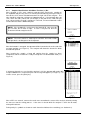
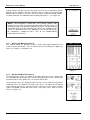
After selecting (1) ID, the instrument shows two options (ID1 and ID2) to record the data (see Figure 4).
Figure 4
Pag.9 / 34
MIX-Rate X20 – USER'S MANUAL
Vital Diagnostics
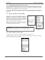
5.1.1 Samples Identification: Sub-Menu Function (1) ID1
After selecting (1) ID1, enter a patient’s code by either entering the number on
the keyboard and pressing enter, or scanning the barcode by passing the tube in
front of the CCD scanner window located on the right side of the analyzer. The
tube should be swiped at a distance of approximately 6”. If the barcode does not
scan, move the tube side-to-side (left to right) in the path of the LED until you
hear a beep and the ID code is accepted. If desired, an external barcode reader
can be connected to the BARCODE port.
NOTE! If the keyboard is used to enter the barcode ID, enter must be
pressed after the ID code is input. If enter is not pressed, then the
instrument will not recognize the ID.
NOTE! The CCD scanner is made up of red LED’s and emits visible
red light that is not dangerous for the operator
Figure 5
After the barcode is accepted, the operator will be instructed to insert the tube into
any open position (see Figure 5). The analyzer will detect the channel in which
the tube was placed.
After inserting the sample, a beep will confirm that the sample has been
recognized, and the instrument is ready to accept the next identification code (see
Figure 6).
Figure 6
If all twenty channels are used and the analyzer is full, the operator will not be able
to input additional ID’s, and an Analyzer Full message will appear (see Figure 7). To
exit the screen, press the [ESC] key.
Figure 7
After all ID’s are entered, return to the main menu to monitor the status of the analysis or before closing
the cover to start the mixing process. If the cover is closed while the analyzer is still in the ID mode,
mixing will not occur.
During analysis, symbols are shown on each channel to indicate time remaining (see Section 4.3).
Pag.10 / 34
Vital Diagnostics
MIX-Rate X20 – USER'S MANUAL
5.1.2 Samples Identification: Sub Menu Function (2) ID2
This function enables the operator to insert a series of sample identification codes following a work list.
Once the codes are entered, the operator must transfer the samples to the channels relative to the
identification codes. This procedure is ideal when one has to transfer many samples from the external
mixer to the instrument quickly, so that results are not affected.
Once the samples have been inserted, return to the main menu to monitor the status of the analysis by
pressing ESC. During analysis, symbols are shown on each channel to indicate time remaining (see
Section 4.3).
5.2
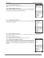
Memory: Main Menu Function (2) MEM
Up to 500 results can be stored in memory at one time,
although the manufacturer recommends clearing the
memory at least every other day. When the instrument is
turned on at the start of a new day, the user is prompted to
delete results (see Figure 8). Pressing enter will erase all
records in memory. ESC aborts this action.
When the memory is full, a warning message will be
displayed, and the analyzer will emit a beep (see Figure 9).
Press CANC key to clear this message.
Figure 8
WARNING! When the memory is full, the instrument will overwrite samples
already in memory, starting with the first sample stored, sample 1.
5.2.1
Figure 9
Memory: Sub-Menu Function (1) Clear
Use option 1 to clear the memory. This will delete all data stored in memory, so
caution should be used. After 1 is pressed, a warning message will appear (see Figure 10). To continue,
press ENT to accept, or press ESC to abort.
Figure 10
Pag.11 / 34
MIX-Rate X20 – USER'S MANUAL
5.2.2
Vital Diagnostics
Memory: Sub-Menu Function (2) Edit
This function allows the operator to edit ID codes, along with the respective results. Move the cursor to
the sample to be changed, press enter, and then edit the ID code or the results (see Figure 11).
Figure 11
5.3
Quality Control: Main Menu Function (3) QC
The screen shown in Figure 12 will be displayed when Function 3 is pressed at the Main Menu.
Figure 12
Pag.12 / 34
Vital Diagnostics
MIX-Rate X20 – USER'S MANUAL
5.3.1 QC INP: Sub-Menu Function (2)
This Function precedes Function 1. The lot number from the hematology control
blood is entered using (2) QC INP. This should be done every time a new lot
number of controls will be used. Press 2, enter the lot number for both the normal
and abnormal controls (found on the package insert), then press ESC to exit.
The lot number has a “checksum” character to ensure that it is entered correctly.
Be certain to enter lot number exactly as written or the code will not be accepted.
When the new code is entered, a screen similar to Figure 13 will appear.
Figure 13
CAUTION! When a new code is entered and accepted, the stored QC data will be
erased. Therefore before deleting stored QC data, “1” must be pressed in order to
confirm the deletion of this stored data. If you wish to print out this data, and do
not wish to delete at this time, Press [ESC] to exit now.
If “1” is pressed the screen shown in Figure 14 will appear.
Press [ENT] to confirm the entry of the new control information and the deletion of
the old data. This will return you to the QC menu.
Figure 14
5.3.2 QC ID: Sub-Menu Function (1)
Once the lot numbers for the QC controls are entered using Function 2 “QC INP”,
the Mixrate-X20 is now ready to measure QC controls and store the results. To
identify that a control is being measured, enter the identification code using the
QC ID, Function 1, before inserting the control samples into the instrument.
Entering the QC ID code will indicate to the Mixrate-X20 that the next sample
placed in the instrument is a control sample. The QC identification code is the lot
number found on the package insert.
Figure 15
Pag.13 / 34
MIX-Rate X20 – USER'S MANUAL
Vital Diagnostics
Control samples may be inserted in any channel as there are no specially assigned
positions for the controls. When the control results are ready, the instrument will
print the data and store the results in the QC memory. When the control samples
are being analyzed, the individual channel display will show “C.” (see Figure 16).
NOTE: Vital Diagnostics recommends using control solutions with
known values for each test and running two levels each day of use, in
accordance with CLIA and local regulatory guidelines. Results obtained
should fall within the limits defined by the day to day variability of the
system as determined in the user laboratory. If the results fall outside
the laboratory’s established limits, refer to the troubleshooting
information in this manual.
Figure 16
5.3.3 QC CH: Sub-Menu Function (4)
This function allows the operator to view a Yuden Plot graph detailing the QC
results over the last 30 days. Press 4 from the QC menu to display the graph (see
Figure 17). To print, see Section 3.3.5.
Figure 17
5.3.4 QC ED: Sub-Menu Function (3)
The calculated QC values are shown on the right side of the screen, and may be
used to replace the theoretical values inserted at beginning of the lot. To adjust the
theoretical values of the graph, press (3) to enter into QC ED.
The theoretical values are displayed to the left of the screen, while the instrument’s
calculated values are display to the right of the screen. To replace the theoretical
values with the new values, select the QC type (either 1 or 2), press enter, and then
replace the MEAN and SD with new values. Once done, press ESC to exit the
menu (see Figure 18).
Figure 18
Pag.14 / 34
Vital Diagnostics
MIX-Rate X20 – USER'S MANUAL
5.3.5 QC PRT: Sub-Menu Function (5)
To print a list of recent QC results, press 5 from the QC menu. The QC results will
print.
5.3.6 QC DEL: Sub-Menu Function (6)
To delete all of the QC data, press 6 from the QC menu. The operator will hear
four shorts beeps, followed by the message shown in Figure 19. Press ENT to
delete the data, or press ESC to abort and exit the menu.
Figure 19
5.4
Printout: Function (4) Print
From the main menu, press 4 to enter the print menu. Using this command displays
three options (see Figure 20).
Figure 20
5.4.1 W.List: Sub-Menu Function (1)
The W.LIST enables the operator to retrieve a summary printout list of the samples currently being
analyzed. Press 1 to print.
5.4.2 Memory: Sub-Menu Function (2)
Pressing 2 prints out a list of all samples analyzed and held in memory.
5.4.3 Memory Range: Sub-Menu Function (3)
Pressing 3 allows the user to enter a range of results to print from memory (see
Figure 21). Insert the sample number to start from in the “From” field and press ENT.
Insert the ending sample number in the “To” field and press ENT. Printing will start
automatically. Pressing [ESC] without entering the From and To fields aborts the
function.
Figure 21
Pag.15 / 34
MIX-Rate X20 – USER'S MANUAL
5.5
Vital Diagnostics
Host: Function (5) Host
To transmit data, press 5 from the Main Menu. Press ENT to send the data, or ESC
to exit the menu.
6.
SYSTEM DESCRIPTION
6.1
Mixrate-X20 Analyzer
Figure 22
The Mixrate-X20 ESR analyzer is an automated instrument controlled by a microprocessor and
exclusively employed for analysis of the erythrocyte sedimentation rate (ESR). Its precision and its ability
to obtain results corrected to a temperature of 18°C (according to Manley) in only 30 minutes, make the
Mixrate-X20 an innovative and versatile system for this kind of analysis. It simultaneously scans 20 test
tubes which are custom-made for ESR with this system.
Mixrate-X20 follows the sedimentation of each sample independently. The instrument can be used for
random and continuous loading of samples to a capacity of 20 test tubes at a time. When a sample has
been analyzed, it can be replaced by another, so it is possible to analyze up to 40 tests per hour.
Mixrate-X20 has been developed to simplify ESR analysis as much as possible, avoiding sample
handling and the operator’s infection risk. To perform the analysis, the operator places the sample test
tube into the instrument. The results are complete in 30 minutes, correlated to one (1) hour Westergren.
This feature allows the instrument to be used directly in the blood sample collection department and in
small laboratories.
In performing the analysis, the Mixrate-X20 surveys the room temperature and converts the result to the
reference temperature of 18°C. (Manley). This is necessary in order to avoid considerable variations of
values due to different room temperatures.
6.2
Results in 15 minutes
Mixrate-X20 can be run in a 15 minute working time mode. If selected, results are displayed after 15
minutes, referenced to 1 hour Westergren. Results are correlated to a one hour value; results cannot be
correlated to 30 minutes or 2 hours in the 15 minute working time mode. The coefficient of correlation at
a 15 minutes working time referenced to the Westergren method is less than R=0.92.
6.3
Symbol Description
1 – Tube inserted, start time
2 – Tube inserted, ¼ complete
3 – Tube inserted, ½ complete
4 – Tube inserted, end time
5 – Empty position
6 – Position with ID, no tube
7 – Test finished ( X )
Pag.16 / 34
Vital Diagnostics
6.4
MIX-Rate X20 – USER'S MANUAL
Sedimentation graph
It is possible to monitor the state of the sedimentation by viewing the sedimentation
graph (see Figure 23). Select the sample to monitor from the main menu by moving
the arrows, and then press Enter to view the graphic. Pressing enter a second time
enables you to print. Moving the arrows up and down allows you to pass to the next
or previous samples.
The graph can only be viewed if the Graph Setting is set to Yes or Auto in the Setup
menu. See Section 2.4, Setup.
6.5
ESR Tubes
Specially designed vacuum and non-vacuum ESR measurement tubes supplied by
Vital Diagnostics must be used to ensure accuracy of measurement for the MixrateX20. Both types of tubes contain sodium citrate at 3.8%. Vacuum tubes are made to
draw 1.2 mL of blood. Refer to package insert for detailed instructions.
Figure 23
7.
OPERATING PROCEDURE
7.1
Sample collection
Samples must be collected following the techniques shown in the Vital Diagnostics ESR Vacuum and
Non-Vacuum package inserts.
The following external factors can alter the ESR value after blood collection:
Dilution ratio
Bubbles
Strongly hemolyzed samples
Sudden agitation
Temperature
Time after sample-taking*
Direct sunlight
Foam
Lipemic samples
Tube inclination
*Time of test:
In accordance with the recommendations of the International Committee for
Standardization in Hematology (ICSH), blood samples collected in this manner should be tested within 4
hours if left at room temperature, or within 6 hours if stored at 4°C. Samples must be brought to room
temperature prior to analysis.
7.2
Labeling
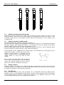
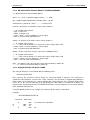
Identify the sample by writing on the original test tube label or by applying a bar code label.
Follow the scheme to carry out this action correctly. In the figure the test tube “A” has the correct blood
level and the original label on which to write the patient code or any other relevant data if the bar code
label is absent. The part marked “H” shows the transparent zone that must be absolutely free and clear
to allow the infrared rays to recognize the end of the blood column. The next test -tube “B” shows the
correct position for the label. Test- tubes C and D illustrate how erroneous applications of the labels
obstruct the reading of the analysis. If the Mixrate-X20 is installed in the surgery, the sample can be
immediately analyzed by placing samples in a free position. Anyway the sample should be analyzed
within three hours, paying attention to external agents shown below that might alter ESR in the preanalysis phase.
Pag.17 / 34
MIX-Rate X20 – USER'S MANUAL
Vital Diagnostics
C
D
YES
NO
NO
LABEL
B
LABEL
A
H
YES
7.3
Sample insertion batch mixing mode
To initialize integrated sample mixing, simply close the plastic cover after samples have been inserted
into the analyzer. Once the cover is closed, samples are automatically mixed for five minutes. Time
remaining is shown on the screen during the mixing. When the mixing feature is used, samples are run
in a batch mode.
7.4
Sample insertion in random mode
For sample identification, follow the instructions in Section 3.1.
After pre-mixing, the sample must be promptly transferred to the analyzer. It is recommended to follow a
numerical sequence while loading the channels. The operator can check the display for the proper
location in which to put the new test tube, if ID function 2 is used.
For the random mode insertion, DO NOT CLOSE THE COVER. If the cover is closed, automatic mixing
will start and analysis in process will be re-started from the beginning.
Channel positions on the support plate are numbered from 1 to 20. Numbering is meant progressively in
groups of 20 samples, so when the analysis of the
sample in channel number 1 is complete, the new
sample inserted in channel 1 automatically becomes
sample number 21, and so on with the other
samples.
After insertion of the twentieth sample, wait for the
results of the first loaded sample. Once complete,
remove the analyzed samples and insert new test
tubes in these channels to continue the analysis.
7.5
Sample removal
During the analysis, the display on the Mixrate-X20 shows the operative state of the instrument, time
remaining symbol (see Section 4.3), and already concluded analysis. Before the final result is shown on
the display, the operator is advised by two short beeps.
7.6
Final Results
When the analysis is finished, the results are printed. The “X” symbol will remain on the display until the
operator removes the corresponding test tube from the analyzer. After removing the tube, the displayed
“X” will disappear within one minute. Removal of the tube causes the displayed result to clear. Once
cleared, the operator may insert a new sample into the channel.
Pag.18 / 34
Vital Diagnostics
7.7
MIX-Rate X20 – USER'S MANUAL
Brief Working Instructions
Set up instrument.
Connect the power supply.
Insert paper in the internal printer.
Turn the instrument on by pressing the switch located at the rear side of the instrument. The display will
show free channels to insert samples as indicated by this symbol [ ].
Sample Insertion – choose from one of the following:
Insert well-mixed sample into any free channel.
Insert unmixed samples into free channels and close the cover to begin the mixing process.
ID1: Scan the barcode and insert well-mixed sample into any free channel.
ID1: Scan the barcode and insert samples into free channels. Close the cover to begin the mixing
process.
ID2: Scan the bar-coded samples in sequence, or enter the ID’s using the keyboard. Then insert wellmixed samples into any free channel.
ID2: Scan the bar-coded samples in sequence, or enter the ID’s using the keyboard. Then insert
samples into any free channel and close the cover to begin the mixing process.
After 30 minutes (or 15 minutes), record the results:
Results will print if the printer is correctly configured in the setup menu.
If Host is connected and configured under setup, the data will be sent to the host according to the set-up
configuration.
After results have been recorded, remove the tubes. [ ] will appear, indicating that this position is free
for introduction of next tube.
Follow points 3 – 5 for additional samples.
8.
SAFETY MEASURES
8.1
User Precautions
Before using the analyzer, the operator must know the rules for handling potentially infectious materials
and for handling the electro-mechanical systems.
8.2
Electrical equipment
As with all electrical equipment, the power supply is a potential source of danger. To prevent the risk of
electrical shock to the user and/or damage to the instrument, the operator should not open the covers of
live electrical parts of the instrument. Only authorized personnel (Vital Diagnostics Service Technicians)
may open the instrument to perform maintenance or repair.
8.3
Mechanical equipment
As a precaution, do not open the instrument until it is disconnected from the power supply. If the power
is on, damage can be caused by moving parts. Do not try to stop the agitator manually or inserting
something between the moving part and the device. This could cause instrument’s damage. The operator can’t
be injured by the agitator, because the moving part is driven by a low power motor and the motor is via
software controlled in order to stop its movement every time an external object/force blocks its movement.
8.4
Samples Analysis
All biological fluids must be considered potentially infectious by the operator. Even if it is not necessary
to remove the cap during the analysis (and so there is no direct contact with blood), the operator must
adopt the national and international standards of precautions to avoid the biological danger.
Specimens (patient samples and controls) and liquid waste should be considered potentially infectious
and capable of transmitting human immuno-deficiency virus (HIV), hepatitis B virus (HBV) and other
bloodborne pathogens. The handling of these substances must be performed in accordance with
established laboratory safety regulations (CDC Universal Precautions; U. S. Department of Health and
Human Services: Recommendation for Prevention of HIV Transmission in Health Care Settings. MMW
Report, Aug 21, 1987, Vol. 36, No. 2S.) in order to minimize risk to laboratory staff. This includes
wearing of gloves, splash protection, etc. Contact with skin and mucous membranes must be avoided.
This also applies to all components of the instrument that are exposed to these substances. If any
specimen is spilled on the instrument, wipe it up immediately and clean the contaminated surface with a
disinfectant of 0.5% sodium hypochlorite solution.Compliance with local regulations pertaining to the
disposal of waste is the responsibility of the operator.Refer to local sources for additional information on
Pag.19 / 34
MIX-Rate X20 – USER'S MANUAL
Vital Diagnostics
correct biohazardous waste disposalQualified technical operators must apply the same warning
procedures for instrument maintenance.
8.5
Notes on safety measures
The operator must pay a special attention to the sample collection. Must use the correct vacuum test
tubes described for this equipment in this manual, since these tubes have been studied to aspirate the
right level of blood. Every attempt to put the blood into test tubes different to the one described, brings
serious dangers of infection due to the risk of sample coming out, and this, moreover, will damage the
optical part inside the instrument and provoke the loss of the guarantee. Refer to the tubes manual to
have more details.On the instrument, to assure a correct use of the instrument, may be placed the
following symbols:
Attention: read use instruction
For in vitro diagnostic use only
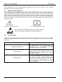
ELECTROSTATIC DISCHARGE SENSITIVE DEVICE (ESDS):
The device could be damaged by electrostatic potentials
8.6
Residual Risks
Despite of the measures taken in the designing of the machine to guarantee a safe use of it, there might
happen reasonably predictable occurrences, whose risk was possible to reduce, but not to eliminate
completely.
RESIDUAL RISKS
Biological contamination
Tubes breaking
Mixing Panel stop
Pag.20 / 34
PROTECTION MEASURES
The operator must wear always gloves and
protection glasses, as prescribed by laboratory
regulations. Do not ever open tubes
Insert and remove tubes from holes maintaining a
vertical position, without applying lateral forces.
Do not try to open the mixing panel in order to
avoid tubes breaking.
Do not try to stop the mixing panel. Do not try to
insert any object between the mixing panel and
the device, in order to avoid mixing panel
damage and/or tubes breaking. Do not try to
touch the internal moving parts when the mixing
panel is open, in order to avoid user and/or
instrument damage.
Vital Diagnostics
MIX-Rate X20 – USER'S MANUAL
9.
PERFORMANCE CRITERIA AND LIMITATIONS
9.1
Performance Criteria
Level sensor for correct blood draw
1.00 to 1.40 mL
Real-time detection measuring points: 10 point intervals
Measuring range:
1 – 140 mm/h
Graphic curve: On printer and display
Short time analysis:
15 minutes
Mechanical / optical precision of detection:
Automatic temperature correction to 18°C.
(Manley table)
+/- 0.2 mm
15°C - 32°C.
QC software for daily control of functionality
9.2
Limitations
Strongly lipemic or hemolytic samples may alter reading capability.
Sedimentation rate values > 140 mm/h will be indicated with this mark: > 140
Temperatures outside the given range will be accepted as 15°C minimum and 32°C maximum.
Anemia under 2.5 million/cubic mm RBC can give reading problems.
As with all ESR analyzers, abnormally high or low hematocrits, along with other hemoglobinopathies,
may affect results.
10.
TEMPERATURE COMPENSATION
10.1
Results correction to 18°C
The results achieved are correlated to the method of reference, considering the room temperature. The
Mixrate-X20 constantly measures the internal temperature and normalizes the values at the temperature
of 18 degrees, according to the Manley table shown in (1) below. This process guarantees better
reproducibility instead of instruments which perform results without temperature compensation.
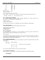
(1)
correct
values
Manley Table
18°C.
15°C.
18°C.
20°C.
25°C.
30°C.
5
4
5
5
6
8
10
9
10
10
12
16
20
18
20
21
25
31
30
27
30
31
37
45
40
36
40
42
49
58
50
46
50
52
60
71
60
55
60
62
71
82
70
63
70
72
82
93
80
72
80
82
93
104
90
81
90
93
103
114
100
90
100
103
114
125
-----------Analysis Temperatures------------
Pag.21 / 34
MIX-Rate X20 – USER'S MANUAL
Vital Diagnostics
Mixrate-X20 converts the results to 18 degrees according to the table if room temperature is within the
range 15 - 32°C. For lower or higher room temperatures, the instrument converts temperature in this
way: 15°C for lower and 32°C for higher temperature.
11.
MAINTENANCE
11.1
Maintenance
The Mixrate-X20 does not require special maintenance, due to the simplicity of the instrument and the
component parts. The most sensitive parts are the infrared sensors inside the instrument.
11.2
Cleaning Instructions
Dust can be removed using an ordinary vacuum cleaner.
Please pay attention to the cleanliness of the test tube positioning plate. When not in use, the
positioning plate must be covered with the Plexiglas cover. Do not clean the upper plate with liquids or
damp cloths; the entry of liquids or solid material into the channels can cause considerable damage to
the instrument.
Pay particular attention to the test tube. The cap must be tightly closed, and the label must be positioned
correctly and completely adhered to the test tube surface. If not, label fragments could fall into the test
tube channel and obstruct a correct reading function during analysis.
12.
ERROR DISPLAYS
12.1
Result Data Error
There is invalid data stored in memory. Contact Technical Support. (Figure 24)
12.2
QC Data Error
There is invalid data within the QC memory. Contact Technical Support.
12.3
Check Printer
If the printer was enabled in the setup function, then the printer must be
connected and ready to print. Check the printer connection, or turn off the printer
in the setup function.
12.4
Check Host Connection
If the host option is enabled in the setup function, then the host system must be
connected and ready to receive data. If this error message is received, check the
host connection, or turn on hosting in the setup function.
12.5
Figure 24
Error: System Stopped
This message will be displayed if the instrument is
not functioning, and has completely stopped due to
mechanical problems with the reading plate
movements. Contact Technical Support.
Figure 25
Pag.22 / 34
Vital Diagnostics
13.
MIX-Rate X20 – USER'S MANUAL
TROUBLESHOOTING
Before calling for a service technician, please check the handling of sample collection, mixing
procedures and operating instructions.
ERROR/ALARM
lev
rem
Temp. "T.ERR"
System stopped
Data result is not printed
Data results seem to be wrong
CCD Scanner does not read
barcode
HOST communication failure
Display background is dark
Memory error
Keyboard malfunction
Clock error
14.
APPENDIX
14.1
Westergren Method
CAUSE
a) Sample level high or low
b) The label was not placed in its
proper position
Sample has been removed
Temperature sensor malfunction
Motor or mechanical defect
a) Printer setup turned off
b) Printer cable
c) Printer malfunction
a) Sample clot
b) Sample has foam
c) Sample measured after 4
hours from sample collection
d) Incorrect sample mixing
a) Scanner configuration wrong
b) Driver board malfunction
c) Scanner malfunction
a) Host cable
b) Configuration disabled
a) Power switch on?
b) Power supply working?
c) Internal problem
Memory battery discharged
Keyboard broken
Clock battery discharged
REMEDY
a) Repeat sample collection
b) Replace label and repeat
analysis
Re-insert sample
Call Technical Support
Call Technical Support
a) Check setup and turn on
b) Check cable
c) Replace printer
a) Repeat sample collection
b) Re-mix gently
c) Repeat sample collection and
promptly process
d) Follow mixing instructions found
in Section 5.3
a) Check setup and turn on
b) Call Technical Support
c) Call Technical Support
Check if cable is connected
Check setup
a) Switch power on
b) Check power supply
c) Call Technical Support
Call Technical Support
Call Technical Support
Call Technical Support
This is the selected method in accordance with the National Committee for Clinical Laboratory Standards
(NCCLS). It consists of a support that keeps the Westergren tubes, containing anticoagulated blood,
perfectly vertical and hermetically sealed.
Westergren tubes have a diameter of 2.5 mm and are graduated up to 200 mm. As soon as the sample
is taken, the venous blood is mixed with a sodium citrate solution, in the ratio of respectively four to one
(1.6 ml of blood + 0.4 ml of sodium citrate). The blood thus prepared and well mixed is drawn into a
Westergren tube up to the zero mark. The tube is placed in the appropriate support and the erythrocyte
level is read after 60 minutes.
14.2
Reference Ranges of Normal ESR Values
Normal ESR Values
After 1 hour mm
male
female
0 - 15
0 - 20
Greer, John P., MD., et al. (2004). Wintrobe Clinical Hematology (11th ed. Vol. 2, pp. 2697).
Philadelphia: Lippincott Williams & Wilkins.
Pag.23 / 34
MIX-Rate X20 – USER'S MANUAL
14.3
Vital Diagnostics
ESR in disease states
ESR – 100 mm or more per hour
Multiple myeloma
Waldenstrom macroglobulinemia
Internal hemorrhage
Etopic pregnancy
Acute hepatitis Malignant lymphoma
Leukemia
Oral contraceptives
Serious anemia
Carcinomas
Menstruation Serious bacterial infections
Sarcomas
Normal pregnancy after the third month
Collagenosis
Biliary or portal cirrhosis
Tuberculosis Ulcerative colitis
Nephrosis
Dextran administration
Postcommissurotomy syndrome
ESR – Moderate increase
Acute and chronic contagious diseases
Acute localized infections
Reactivation of a chronic infection
Rheumatoid arthritis
Malignant tumor with necrosis
Hypothyroidism
Nephrosis
Rheumatic illness
Myocardial infarction
Hyperthyroidism
Lead or arsenic poisoning
ESR – Normal values
First stage acute appendicitis Whooping cough
Malarial paroxysm
Cirrhosis of the liver
Arthritis Mononucleosis
Acute allergies Virus infections without complications
Peptic ulcer
Typhoid fever
Rheumatic carditis with cardiac decompensation
Bibliography
THYGESEN, J.E.(1942). The mechanism of blood sedimentation. Acta Medica Scandinavia, Suppl. 134.
WINTROBE,M.M. and Landsberg, J.W. (1935). A standardized technique for the blood sedimentation
test. American Journal of Medical Sciences, 189, 102
HARDWICKE, J. and SQUIRE, J.R. (1965). The basis of the erythrocyte sedimentation rate. Clinical
Science, 11, 333
International Committee for Standardization in Hematology (1977). Recommendation for measurement
of erythrocyte sedimentation rate of human blood. American Journal of Clinical Pathology, 68,505
LASCARI, A.D. (1972). The erythrocyte sedimentation rate. Pediatric Clinics of North America, 19,1113
MANLEY, R.W. (1957). The effect of room temperature on erythrocyte sedimentation rate and its
corrections. Journal of Clinical Pathology, 10, 354
CDC Universal Precautions; U. S. Department of Health and Human Services: Recommendation for
Prevention of HIV Transmission in Health Care Settings. MMW Report, Aug 21, 1987, Vol. 36, No. 2S.
Pag.24 / 34
Vital Diagnostics
14.4
MIX-Rate X20 – USER'S MANUAL
Hardware specifications
14.4.1 Power Supply Units Specification
Manufacturer: Dee Van Enterprises (DVE)
Model:
DSA-0421S-12
Input:
100 - 240 Vac, 47 - 63 Hz
Output: +12Vdc, 3.5A
Warning: For user's security and instrument safety, use only original power supply unit.
NOTE: In case of power supply cord substitution, use only power supply cord listed/certified minimum 18
AVG, 3C VW-1 Min. 75°C, minimum SVT type.
14.4.2 Power Connector Description
PIN
DIRECTION
NAME DESCRIPTION
-------------------------------------------------1
internal +12V Power supply 12Vdc, 3.5A
2
external
GND Ground
14.4.3 Printer Connector Description
Instrument 9 pin female connector:
PIN
DIRECTION
NAME DESCRIPTION
-------------------------------------------------1
----(Do not connect!)
2
----(Do not connect!)
3
OUTPUT
TXD
Serial data output
4
OUTPUT
DTR Data Terminal Ready
5
--GND Ground
6
----(Do not connect!)
7
----(Do not connect!)
8
INPUT CTS
Clear to send
9
----(Do not connect!)
14.5
Host specifications
14.5.1 Host Connector Description
Instrument 9 pin male connector:
PIN
DIRECTION
NAME DESCRIPTION
-----------------------------------------------------1
----(Do not connect!)
2
INPUT RXD Serial data input
3
OUTPUT
TXD
Serial data output
4
OUTPUT
DTR Data Terminal Ready
5
--GND Ground
6
----(Do not connect!)
7
----(Do not connect!)
8
INPUT CTS
Clear to send
9
----(Do not connect!)
14.5.2 Barcode Connector Description
Instrument 9 pin male connector:
PIN
DIRECTION
NAME DESCRIPTION
------------------------------------------------------
Pag.25 / 34
MIX-Rate X20 – USER'S MANUAL
1
2
3
4
5
6
7
8
9
----INPUT RXD
----OUTPUT
--GND
-----------------
Vital Diagnostics
(Do not connect!)
Serial data input
(Do not connect!)
DTR Data Terminal Ready
Ground
(Do not connect!)
(Do not connect!)
(Do not connect!)
(Do not connect!)
14.5.3 Host Connection Specifications - Communications Protocol
EXAMPLE OF A CONNECTION TO A PC IBM COMPATIBLE COMPUTER
Note: Connectors are 9 pin female.
2 ------------- 3
3 ------------- 2
4 ------------- 8
8 ------------- 4
5 ------------- 5
14.5.4 HOST CONNECTOR SIGNALS DESCRIPTION
Data format is: 9600 bps, 8 data bit, 1 stop bit, no parity, hardware protocol RTS-CTS.
In order to make this document clear the character tilde ("~") is used in place of a space (" ") when there
is more of one space and spaces are important for data collection.
Control characters sent by the instrument is:
STX code (2 decimal) in this document, replaced by the string "[STX]";
ETX code (3 decimal) in this document, replaced by the string "[ETX]";
14.5.5 HOST/DATA TRANSMISSION" REQUEST FROM HOST COMPUTER
The host computer could require data transmission by sending the character "?". Data transmission starts
only if the operator is not using the instrument. If the instrument still executing a command menu,
characters will not be transmitted.
14.5.6 MESSAGES SENT IN THE BEGINNING
Instrument model: "MODEL: xxxxxxxx V.1.0"
Note: The model name and version of the software can be different.
Device configuration: "MODE: 15' T.CORRECTION ON", "MODE: 30' T.CORRECTION ON"
"MODE: 60' T.CORRECTION ON"
or
NOTE: Values 15, 30 and 60 depend on the analysis time mode, respectively 15', 30' or 60'. The string
"~T.CORRECTION ON" is transmitted only if the temperature correction is enabled.
Date and Time: "DATE: GG/MM/AAAA~~HH:MM"
Operating temperature: "TEMPERATURE: gg.rC"
where: gg.r is the operating temperature value with one decimal. Transmitted only if the temperature
correction is enabled.
Pag.26 / 34
Vital Diagnostics
MIX-Rate X20 – USER'S MANUAL
14.5.7 MESSAGE SENT FOR ANY RESULT STORED IN MEMORY
"sss pp cccccccccccc mmmm 30mm 60mm"
where: sss = is the sequential sample number ( ~~1 - 999).
pp = sample location identified by a number (from ~1 to 20).
cccccccccccc = patient ID - code ("............" if not present).
mmmm = 30' analysis result whose values can be shown as:
"~~~0" sample under analysis.
"~LEV" if error level.
"~REM" if sample error.
"~mmm" mmm = result in millimeters. (on the right).
">140" result more than 140 millimeters.
30mm = 1h analysis result, whose values can be shown as:
"~~~0" sample under analysis.
"~~~~" if the result of mmmm is an error or the value is higher than >140.
"~mmm" mmm = result in millimeters. (on the right).
">140" result more than 140 millimeters.
60mm = 2h the result of the analysis can have the following values:
"~~~0" sample under analysis.
"~~~~" if the result of mmmm is an error or the value is higher than >140.
"~mmm" mmm = result in millimeters. (on the right).
">140" result more than 140 millimeters.
Note: the 60mm result is present only if the instrument works in mode: 60'
"~~~~" is send, if the instrument works in mode: 30'.
14.5.8 DESCRIPTION OF THE DATA FRAME
Any string of characters is transmitted with the following frame:
<STX>string<ETX>ECC
ECC represent the checksum used to detect if a string transmitted is defective. The checksum is
encoded as two characters sent after the <ETX> character. The checksum is computed by adding the
binary values of the characters in a string (modulo 256) and keeping the least significant 8 bits of the
result. The 8 bits can be considered as two groups of 4 bits which are converted to ASCII and
represented in hexadecimal format. The two ASCII characters are transmitted as the checksum with the
most significant character first.
Using the following frame as an example, the checksum for this frame is calculated.
Example:
<STX>ABCDEFGHI<ETX>70
Character
ASCII value
A
B
C
066
067
D
065
2nd
etc
068
1st character for calculation
etc
Pag.27 / 34
MIX-Rate X20 – USER'S MANUAL
E
F
G
H
I
<ETX>
069
070
071
072
073
003
Vital Diagnostics
etc
etc
etc
etc
etc
etc
Total sum value =
624
Module 256 (624) is: 112
Then 112 (decimal) is 70 (hex) ECC is: 70.
If ECC length is 1 character, the resultant ECC is adding a zero character (ASCII 48) on the left.
Example: First ECC: A
14.6
The resultant ECC is 0A
Interfacing specifications
This document contains moderately complex technical information. The reader should have an
intermediate level of knowledge in the following areas:
Computer systems
Computer communications
This manual assumes that the users of Windows systems have logged on as Administrator.
14.6.1 Basic Procedure
The basic procedure to setup an Mixrate-X20 and a host system is:
Connect the two systems together
Configure Mixrate-X20
Configure host PC
14.6.2 Configuration
The Mixrate-X20 can be interfaced to an external computer system using a 9 pin serial cable. The
Mixrate-X20 host settings can be configured in 3 modes, these are:
No, Yes or Auto
In Auto mode, the Mixrate-X20 sends data when results are ready, or the host computer can request a
data dump of the complete Mixrate-X20 memory by sending a ? character to the Mixrate-X20. This
request will be ignored if the Mixrate-X20 is busy.
14.6.3 Hardware Configuration
The Mixrate-X20 can be interfaced to an external computer system with a 9 pin Serial cable. The cable
configuration is:
Host Side
Pin
Pin
Mixrate-X20 Side
2 ----------------- 3
3 ----------------- 2
4 ----------------- 8
8 ----------------- 4
5 ----------------- 5
Both sides use female connectors.
Press 6 from the Mixrate-X20 main menu and set the host to AUTO.
14.6.4 Software Configuration
The host system uses a standard PC serial COM port configured with the following settings:
9600 bits/second
8
Data bits
Pag.28 / 34
Vital Diagnostics
MIX-Rate X20 – USER'S MANUAL
N
No Parity
1
Stop bit
Hardware handshake (RTS-CTS)
The host system must be configured to read data in the format described in Section C.6. This is the
responsibility of the customer or host PC vendor. The test procedure described in section 4 will verify
that the Mixrate-X20 is transmitting data to the host PC.
Pag.29 / 34
MIX-Rate X20 – USER'S MANUAL
14.7
Vital Diagnostics
Data format & example data file
5.1 The data format sent out by the Mixrate-X20 consists of the following format:
STX (message) ETX and a Checksum derived from (message) & ETX
5.2 Startup message:
On startup, the Mixrate-X20 transmits:
The model number and version of software
The device configuration – analysis time mode
Date & time
Operating temperature
Some of the above are optional and depend on instrument settings.
5.3 The file shown in FIG 34 is an example transmission from the Mixrate-X20. For the first sample, the
Sample ID number is 4037340, the sequence number is 2, 1, and the result is 62. BOLD = STX & ETX
UNDERLINE = Checksum, Black = data
Grey = Next sample data.
Hex
02 20 20 32 20 20 31 20 34 30 33 37 33 34 30 2E
2E 2E 2E 2E 20 20 20 20 20 20 36 32 20 20 20 20
20 03 31 39 02 20 20 33 20 20 32 20 34 30 33 38
30 32 31 30 31 2E 2E 2E 20 20 20 20 20 20 20 37
20 20 20 20 20 03 30 43 02 20 20 34 20 32 34 20
34 30 33 38 32 37 33 2E 2E 2E 2E 2E 20 20 20 20
20 20 20 37 20 20 20 20 20 03 32 35
7
ASCII
. 2 1 4037340.
....
62
.19. 3 2 4038
02101...
7
.0C. 4 24
4038273.....
.25
Fig 26 Sample Transmission
5.4 Checksum calculation
In the example of FIG 34, the checksum is 31 39. This is derived by:
Adding all the hex data in the data frame between ETX and STX, including ETX but not STX. This is
equal to 0519 hex.
The least significant byte from 0519 is 19, the ASCII equivalent of these digits is 31 39 – the check sum
data.
5.5 Host participation
IMPORTANT: There is no host intervention in the communication protocol. If the host finds the
checksum does not match the data, the only thing the host can do is to request the Mixrate-X20 resend
data by sending a “?” character.
Pag.30 / 34
Vital Diagnostics
15.
MIX-Rate X20 – USER'S MANUAL
INTERNAL BARCODE SCANNER DEFAULT CONFIGURATION
The instrument is supplied with a default
barcode configuration that enables the
reading of the most commonly used
barcode label formats.
DEFAULTS
START
The barcode scanner manual, supplied
with the instrument, can be used to enable
or change configuration for other formats.
Use the barcode scanner to change
settings.
RS232
Caution! Wrong configuration codes may
lead to barcode scanner malfunction.
FLASH
In case of reading problems, this page can
be used to reset the scanner to the factory
setting.
CR
Turn on the instrument, wait for the self
test to complete and then read all barcode
labels on this page, from top to bottom.
The configuration is automatically saved in
the barcode scanner.
ALL
END
SAVE
Pag.31 / 34
MIX-Rate X20 – USER'S MANUAL
16.
Vital Diagnostics
TECHNICAL SPECIFICATIONS
Area of application:
Erythrocyte sedimentation rate analysis
Operating Conditions:
15° - 32°C room temperature
Humidity: 45% - 85%
Tube employed:
Special 8 x 120 mm tubes
Reading channels:
20
Analysis time:
15, 30 or 60 minutes
Analytical capacity:
Maximum 40 tests/hour (30 minute working time)
Maximum 80 tests/hour (15 minute working time)
Loading capacity:
Maximum 20 samples at a time
Loading pattern:
Random
Results:
In Westergren mm/h (by interpolation)
Temperature correction:
Automatic compensation referenced to 18°(Manley)
Measuring method:
Infrared beam
Reading resolution:
+/- 0.2 mm
Results resolution:
+/- 1 mm
Acceptable blood draw level:
0.90 to 1.20 ml
Display:
GRAPHIC LCD with backlight
Interface:
RS232 for printer, host and barcode scanner
Instrument size:
Height 200 mm
Width 330 mm
Depth 310 mm
Weight:
about 5 kg
Voltage:
External power supply: 100 - 240 Vac, 47 - 63 Hz
12 Vdc, 3.5A
Pag.32 / 34
Vital Diagnostics
17.
MIX-Rate X20 – USER'S MANUAL
EC DECLARATION
DICHIARAZIONE DI CONFORMITÁ CE
EC DECLARATION OF CONFORMITY
conforme all’Allegato III della Direttiva 98/79/CE Dispositivi Medico-Diagnostici In Vitro
conforme all’Allegato II della Direttiva 2006/42/CE Direttiva Macchine
according to Annex III of the Directive 98/79/CE In Vitro Diagnostic Medical Devices
according to Annex II of the Directive 2006/42/CE
fabbricante
manufacturer
Vital Diagnostics S.r.l.
Via Balzella 41/G/4
indirizzo
address
47100 FORLI’
ITALIA
telefono
phone
0039 0543 721220
fax
fax
0039 0543 796001
Identificazione dei prodotti
Product identification
Analizzatore Automatico della VES
ESR Automated Analyzer
Nome commerciale
Brand name
Mixrate-X20
Numero/i di catalogo
Part number/s
PRD-X20-EL-08TKN
classificazione dei prodotti
product identification
dispositivi diversi da quelli elencati nell’Allegato II della Direttiva 98/79/CE
devices other then those mentioned in Annex II of the Directive 98/79/EC
Si dichiara sotto la propria responsabilità che
i dispositivi sopraelencati rispettano le disposizioni applicabili delle seguenti direttive:
Hereby we declare under our sole responsibility that
the above mentioned devices meet the applicable provisions of the following Directives:
Direttiva 98/79/CE
Direttiva 2006/42/CE
Direttiva 2004/108/CE (Compatibilità Elettromagnetica)
Direttiva 2006/95/CE (Bassa Tensione)
Direttiva 2002/96/CE e 2003/108/CE (RAEE)
Direttiva 2002/95/CE (RoHs)
Tutta la documentazione tecnica comprovante il rispetto dei requisiti applicabili delle Direttive elencate,
è conservata a cura del Fabbricante
All the technical documents required to demonstrate the conformity to the listed Directives,
are kept by the Manufacturer
luogo e data
place and date
Forlì, 11/03/2008
anno di immissione in commercio
year of introduction on the market
2006
firma
signature
timbro della Società
Pag.33 / 34
MIX-Rate X20 – USER'S MANUAL
18.
Vital Diagnostics
DISPOSAL AND RECYCLING
Herewith we declare that this instrument is subject to the European Directive 2002/96/EC (RAEE
Directive).
Therefore the instrument must be disposed separately, not as urban waste and delivered to the specific
collection center in according to the Directive 2002/96/EC.
The user can ask to the dealer the collection of the instrument if a new instrument is ordered to replace
the old one.
On the instrument there is a label with the symbol shown in this page. The symbol means that the
instrument can not be disposed as urban waste.
Pag.34 / 34