1
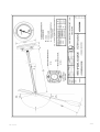
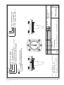
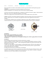
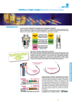
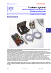
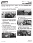
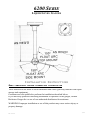
6200 SERIE
LIQUID LEVEL GAUGES
INSTALLATION INSTRUCTIONS
READ COMPLETELY BEFORE ATTEMPTING INSTALLATION
These instructions are made to assist tradesmen and others generally familiar with liquid
storage tank equipment.
Consumers are not qualified to perform the installation described below.
If you have any question concerning installation or operation of the gauges, contact
Rochester Gauges Int. or one of our authorised distributors for assistance.
WARNING: Improper installation or use of this product may cause serious injury or
property damage.
1/20
28 Jan 09
2/20
28 Jan 09
Description of Product
6200 Serie gauges are magnetic float gauges designed to be installed on storage tanks with
diameter up to 2000mm. These items are currently used to gauge products such as LPG, Ammonia,
hydraulic oils, fuel oil, etc...
These gauges are designed for pressure up to 25 bars and temperature of -20°C up to 60°C if
adequate float is used (30 bars with special senior head, model M6200).
These gauges operate simply by means of a float actuating a powerful magnet inside the container
which in turn provides an invisible “magnetic coupling”, through a solid head, with the magnet of the
pointer in the dial. The dial may be removed and replaced quickly at any time without loss of liquid,
pressure, vacuum or costly downtime.
Mounting Position
The gauge can be manufactured for top, side, end or angle mounting.
Vertical
Horizontal
Horizontal
Angle
: 1 Top Mounted
: 2 End mounted
: 3 Side mounted
: 4 Angle mounted
(Angle α for angle mounted gauge is specified from
horizontal, positive above horizontal, negative below
horizontal)
3/20
28 Jan 09
4/20
28 Jan 09
Gauges type
These gauges can be supplied with Senior or Junior Head with direct reading (dial size Jr 40mm, Sr 58mm
or 4" 100mm) or with sensor (TwinSiteTM dial)
Options:
Type
Number
Head size
Dial
Mounting
6241/6251
6244/6254
6240/6250
6243/6253
6260
6281
6284
6280
6283
6290
6293
Junior
Junior
Senior
Senior
Senior
Junior
Junior
Senior
Senior
Senior
Senior
TwinSite
TwinSite
TwinSite
TwinSite
Side view
Direct
Direct
Direct
Direct
Direct 4"
Direct 4"
Top
End, side, angle
Top
End, side, angle
Top
Top
End, side, angle
Top
End, side, angle
Top
End, side, angle
Head: Junior Brass head → prefix B
Float: Nitrophyl float → prefix C (for fuel or low pressure application)
Stainless Steel float → prefix A
Plastic or Metal head cover
Inspection of gauge
Before attempting the installation of the gauge, check if the gauge is adequate for your application. The
gauges are supplied packed in a cardboard box with a sticker indicating the model, the main dimensions
(stem and float) of the gauge, the mounting position, the tank dimensions for which the gauge has been
manufactured and the product intended to be gauged.
a) Check of the dimensions (see attached drawing)
- Stem length: by design and for horizontal cylindrical tank, the pivot point of the float should be at
the mid height of the tank (50% plane). Hence Stem length should be:
for top or angle mounting S = 0.5*OD + H (OD = tank outside diameter, H = riser dimension)
for end or side mounting S = 0.3*OD + H or 0.4*OD + H
However for this type of mounting the stem length is less critical, as the gauge is installed at the mid height
of the tank
- Float length: the float length is function of the internal diameter (ID) of the tank, the type of dial
used and the float used. For the 6200 Serie and horizontal
5/20
28 Jan 09
6/20
28 Jan 09
cylindrical tank, the dial is generally graduated from 5% to 95%. In this case float length should be equal
to:
F = 0.428*ID + 44.5 (with alu float 6-406 of length 105mm)
F= 0.428*ID + 32 (with alu float 6-407 of length 76mm or Stainless Steel float 6045S0 of length 64mm)
F = 0.428*ID + 31 (with nitril rubber float 6-583 of length 62mm)
OR F = 0.5*ID – 10mm if above formula has a result in F > 0.5*ID – 10.
b) Check the gauge mounting position on the tank.
To check the mounting position for which the gauge has been manufactured, hold the stem in the
mounting position, move the float to the horizontal plane and check the needle on the dial which should
indicate 50% ± 5%.
c) Check the gauge counterbalance with your application
If the float axis is equipped with a lead counterweight the float arm has been counterbalanced to
gauge a product of low specific gravity. To check if the float arm has been counterbalanced to the product
you intend the gauge, set the float bulb on a scale and maintain the float arm horizontally.
The weight of the float should be:
Type of float
Product to be gauged
Weight (±2gr)
6-406 Alu
L = 105mm LPG δ = 0.55
13 gr.
6-407 Alu
L = 76mm
LPG δ = 0.55
9 gr.
6-583 Nitril rubber L = 62mm
LPG δ = 0.55
13 gr.
6045S0 SS
L = 64mm
Ammonia δ = 0.65 13 gr.
For liquid of a different specific gravity the weight should be proportional to the specific gravity
scale
Note
For Ammonia service never use a gauge with brass head and always use a gauge with Stainless Steel float.
d) Check proper movement of the float
Although the gauges are 100% checked before packing, it is necessary to verify that the gauge has
not been damaged in transit. In order to verify that, hold the gauge in its intended mounting position and
move the float arm slowly upwards and downwards. This movement should be smooth without any heavy
point.
7/20
28 Jan 09
Gauge adapter
In general an adapter is welded on the tank. Check if the adequate adapter
is used for the gauge and the gasket supplied.
Mounting of the gauge
Fit gasket onto gauge gasket seat.
Carefully insert float into adapter or coupling and work gauge's gear housing and support through adapter,
being careful not to bend or damage them.
Check to see that gasket is properly seated in adapter gasket recess.
Align head for proper orientation of float inside the tank. Torque screws evenly in several steps to the
desired torque value. When torquing use a crossing torque pattern.
Caution: Do not overtorque. Do not re-torque later unless leaking. Overtightening may cause damage to
head and gasket.
Screw Size
M6 or ¼"-28UNF
M8 or 5/16-24UNF
Dry torque
2.3 to 5.6 Nm
3.4 to 6.8 Nm
Gasket
Buna –N
Buna-N
8/20
28 Jan 09
Marking
The lateral faces of the head are marked with the necessary data requested to identify the gauge such as
batch number, СЄ marks, tank data and model number.
The B in front of the batch number indicates that the gauge has been manufactured by ROCHESTER
GAUGES INTERNATIONAL S.A., Belgium.
Warranty Statement
ROCHESTER GAUGES INTERNATIONAL S.A. guarantees its products for a period of 12 months from date
of invoice.
This warranty is limited to our product and consists of the repair or the replacement of the product if the
factory inspection finds the cause of malfunction to be defective material or workmanship. The material
should be returned to our factory at purchaser's cost.
No claim for misapplication, labour, direct or consequential damage will be allowed.
Returned material procedure:
In order to efficiently process any materials that are returned, it is essential that following instructions are
provided with the returned material:
- Purchaser name
- Description of material
- Batch number
- Reason for return
- Claim description
- Description of application and misfunction.
9/20
28 Jan 09
28 Jan 09
10/20
Rev A : Batch number is 4 digits instead of 3
Manufacturnig month is 1 digit instead of 2
Rev B : 1 digit Manufacturnig month: 0 to 9, O, N, D
Erase Manufacturer logo
Erase Letters height: 3mm
0029PP
A4
Size
Scale
Drawn
Verif
Modif.
JN
DH
28 Jan 09
Material
TTTT-stem-dia
PED marking
Ensemble PV
A
B
ROCHESTER GAUGES INT. S.A.
BELGIUM
TTTT-stem-dia
dia = tank diameter (mm)
stem = stem length(mm)
TTTT = gauge type (6281, ...)
view (contained in Install. Instructions 6200 series)
PED marking
Gauge serie 6200
Name
Date
27 fev 02
PP = max pressure(bar)
Notified body identification
FFFF= Batch number
AA = Manufacturing year
M = Manufacturing month (1 to 9, O, N, D)
B = Manufactured by RGI Belgium
BM-AAFFFF
0029PP
BM-AA FFFF
Replacing Dial
READ
COMPLETELY
BEFORE
ATTEMPTING
INSTALLATION
These instructions are made to assist tradesmen and others generally familiar with liquid storage tank
equipment.
Consumers are not qualified to perform the installation described below.
Improper installation or use of dial may cause serious injury or property damage.
If you have any question concerning choice, installation or operation of the dial or gauge, contact Rochester
gauges Intl. or one of our authorised distributors for assistance.
Check side of gauge head for model number and ask for technical data sheet for your model.
Caution: determine and install the appropriate magnetic dial based on gauge and system requirements. The
dial type supplied may not be suitable for all applications and for those applications other dials are
available.
The information contained herein is intended for guideline use only and the suitability of any dial or
TwinSiteTM sender for a particular application must be determined by the user prior to installation.
Direct reading Std
JR or SR Dial
Side view dial
TwinSiteTM Sender
WARNING:
Do not remove gauge mounting screws or bolts.
Tank contains high pressure and flammable gas.
A hazard of fire or explosion may exist if gauge mounting screws, bolts or gauge heads are loosened
or removed
GUIDELINE:
Record reading on old dial, disconnect electrical connection to Twinsite;
Using a #1 Phillips screwdriver, remove two #6 screws retaining old dial chamber and remove old dial.
Install replacement dial or TwinSiteTM sender assuring that dial chamber fits gauge head and torque dial
mounting screws at 0.4Nm.
Compare new dial reading to recorded reading or estimated tank contents. If the new dial reading is not
correct, remove dial and use a magnet near the back of the dial, rotate the pointer to approximate the
expected dial reading and re-install dial.
If reading still seems incorrect, the dial may be a wrong type.
CAUTION: improper dial selection or application may result in inaccurate gauge readings. Release of tank
contents as well as damage to equipment and safety hazard may result if tank is overfilled. Combustible
exhaustion may occur if tank contents are less than indicated.
11/20
28 Jan 09
ROCHESTER GAUGES INTERNATIONAL S.A.
Z.I. WAVRE NORD
AV. LAVOISIER, 6
1300 WAVRE
BELGIUM
Tél: 32 (0) 10 24 10 10
Fax: 32 (0) 10 22 81 39
http://www.rochester-gauges.be
R.C. NIVELLES 65.461
TVA : BE 440.371.387
DECLARATION OF CONFORMITY
Original attached to the invoice
I, the undersigned, certify that the level gauge accessories for pressurised tank of
a diameter up to 2000 mm of serie 6200, model
manufactured under batch n°
in our factory, 6 avenue Lavoisier, B-1300 Wavre, Belgium
are in conformity with the European Directives and Standards applicable today:
Directive 97/23/CE following modules B + D certified by:
- APRAGAZ, chaussée de Vilvoorde 156, B-1120 BRUXELLES, Belgium
- EURO QUALITY SYSTEMS, bvd de la république 50,
F-92250 La Garenne Colombe, France
This serie has been certified by the notified body n°0029 under n° 02/BE/329
The gauges have been manufactured in conformity with following standards:
PrEN 13799, EN 549
Note:
- The Directive 89/392/CE (machinery) does not apply as this equipment has to be used as part of an assembly.
- In case of use of a sensor for remote reading, the Directive 94/9/CE (ATEX) applies.
Date:
Michel DUFAYS
12/20
28 Jan 09