1
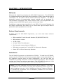
ACC-964CD User’s Manual First Edition, June 2003 Copyright 2003 BY Bridge Embedded Systems, Inc First Edition, June 2003 All rights reserved. Printed in the United States of America. Maxon name used by Bridge Embedded Systems, Inc. with permission IBM is a registered trademark of International Business Machines Corporation Windows is a registered trademark of Microsoft Corporation InstallShield is a registered trademark of Installshield Software Corporation Motorola is a registered trademark of Motorola Corporation For Technical Support, please contact: Midland Radio Corporation 1120 Clay Street North Kansas City, MO 64116 Tel: (816)241-8500 Fax: (816)241-5713 www.MidlandRadio.com TABLE OF CONTENTS CHAPTER 1: INTRODUCTION ........................................................................ 1 Welcome.................................................................................................... 1 System Requirements .................................................................................. 1 Installation ................................................................................................. 1 CHAPTER 2: GETTING STARTED.................................................................... 2 Overview ................................................................................................... 2 A Typical Programming Session ..................................................................... 2 CHAPTER 3: GRAPHICAL INTERFACE ............................................................ 4 Overview ................................................................................................... 4 Tree View................................................................................................... 5 List View .................................................................................................... 5 Menu Items ................................................................................................ 6 Speed Buttons ............................................................................................ 7 CHAPTER 4: CREATING/EDITING PERSONALITIES....................................... 8 Overview ................................................................................................... 8 Creating a New Personality ........................................................................... 8 Editing Personalities..................................................................................... 8 Deleting Channels or Users ........................................................................... 9 CHAPTER 5: I/O OPERATIONS.................................................................... 10 Overview ..................................................................................................10 Opening Personalities from a File ..................................................................10 Saving Personalities to a File........................................................................10 Connecting the SRC-40 to a PC ....................................................................11 Reading Personalities from an SRC-40 ...........................................................11 Programming Personalities to an SRC-40 .......................................................12 CHAPTER 6: SYSTEM SETTINGS .................................................................. 13 Overview ..................................................................................................13 System Settings in Detail ............................................................................13 CHAPTER 7: CHANNEL SETTINGS ............................................................... 14 Overview ..................................................................................................14 Channel Settings in Detail............................................................................15 Base Station Settings in Detail .....................................................................17 CHAPTER 8: USER SETTINGS ...................................................................... 18 Overview ..................................................................................................18 User Slots .................................................................................................19 User Settings in Detail ................................................................................19 CHAPTER 9: EXPORTING DATA ................................................................... 21 Overview ..................................................................................................21 Export as Plain Text....................................................................................21 Export as CSV............................................................................................21 CHAPTER 10: AIRTIME LOGGING................................................................ 22 Overview ..................................................................................................22 Reading and Saving Airtime Logs..................................................................22 Resetting Airtime Logs ................................................................................22 Suggested Uses of Airtime Logs....................................................................22 ACC-964CD User’s Manual Page i CHAPTER 1: INTRODUCTION Welcome Welcome and thanks for purchasing the ACC-964CD Programmer. The ACC-964CD is a Windows application that allows system operators to easily create and program a “personality” for the Maxon SRC-40 Series Community Repeater. An SRC-40 personality consists of programmable channel settings such as broadcast ID, receive/transmit frequencies, and remote access codes, plus programmable user settings such as DCS/CTCSS squelch options and courtesy tones. In addition to programming personalities for your SRC-40 Community Repeater, the ACC-964CD Programmer also allows you to view airtime logs and export SRC-40 personalities as a spreadsheet or a text file. System Requirements To begin using the ACC-964CD Programmer, you must meet these minimum requirements: • IBM compatible PC with Microsoft Windows (95/98/ME/NT/2000/XP) • 486 processor or faster • 16 MB of RAM • At least 5 MB of free disk space • One free serial communications (COM) port • DB9 cable to connect the PC to the SRC-40 Community Repeater • Maxon SRC-40 Series Community Repeater Installation The ACC-964CD Programmer is distributed on CD-ROM. To install the ACC-964CD, simply insert the CD and then let the setup program begin running automatically. If the installation program does not begin automatically, you can also start the installation by running “setup.exe” in the root directory of the CD. Once it begins running, just follow the onscreen instructions. The ACC-964CD Programmer uses InstallShield, a utility commonly used to install Windows applications. NOTE: If you have installed a previous version of the ACC-964CD or if you need to reinstall the current version, you must first uninstall the version on your PC before installing a new one. Use to “Add/Remove Program” feature of Windows to uninstall the ACC-964CD. The un-installation procedure will not remove custom personality files. ACC-964CD User’s Manual Page 1 CHAPTER 2: GETTING STARTED Overview We recommend that you read this entire manual before you begin programming your SRC-40 Community Repeater. However, if you want to get started programming right away, the steps below offer a quick overview of a typical SRC-40 programming session. It is also helpful to know what steps that you will need to complete to program the SRC-40 so that you can keep them in mind while reading the remainder of this manual. A Typical Programming Session A typical SRC-40 programming session involves creating at least one channel and one user per channel, and then programming your personality to the SRC-40 unit. To do so, you must complete the following steps: 1. Start with a base personality Every programming session begins with one of three options: create a new personality from scratch, load a saved personality from disk, or read the personality currently programmed to the SRC-40 repeater. The remaining steps below assume that you are creating a new personality from scratch. To create a new personality, choose New from the File menu. See “Chapter 4: Creating and Editing Personalities” for more information about personalities. 2. Specify system settings When you create a new personality, you must specify if you are programming the VHF (SRC-40V) or the UHF (SRC-40U) model. This determines the valid range of receive/transmit frequencies. You can also specify an optional password to protect your personality data from unauthorized users. See “Chapter 6: System Settings” for more information about system settings. 3. Create a new channel The SRC-40 must be programmed with at least one channel. To create a new channel, right-click an empty channel slot in the tree view, and choose New Channel from the popup menu. During the channel creation process, you can specify channel settings such as the broadcast ID, receive/transmit frequencies, and the length of the TX timeout timer. When you create a channel, you will also need to specify base station settings if you plan to use the SRC-40 as a base station. See “Chapter 7: Channel Settings” for more information about channels. Page 2 ACC-964CD User’s Manual 4. Create a new user Each channel needs at least one user. To create a new user, right-click an empty user slot in the tree view and choose New User from the popup menu. During the user creation process, you can specify user settings such as the user ID, receive/transmit squelch options (CTCSS tone or DCS code) and courtesy tones. Note that the user in Slot 0 is the designated System Operator, which is the only user that has remote programming privileges. The users in Slots 1 through 63 are normal users. See “Chapter 8: User Settings” for more information about users. 5. Create additional users as needed Repeat step 4 above for any additional users that you wish to add to the channel. The SRC-40 can have a maximum of 64 users per channel. 6. Create additional channels as needed Repeat steps 3 through 5 above for any additional channels that you wish to add to the SRC-40. The SRC-40 can have a maximum of 16 channels. 7. Save your personality to disk (optional) As with any software program, it is always a good idea to backup your work periodically. If you haven’t done so by now, this is a good point to save your personality to disk. See “Chapter 5: Personality I/O Operations” for more information about saving personalities as a file. 8. Program your personality to the SRC-40 After you’ve created all the channels and users for your system, you’re ready to program the custom personality to the SRC-40. Connect your PC to the SRC-40 using the included DB9 cable and start the programming process. See “Chapter 5: Personality I/O Operations” for more information about programming your custom personality to the SRC-40. Once the programming process is complete, you can verify that your personality was properly programmed by scrolling through the channels pressing the and buttons on the SRC-40’s front panel. On any given channel, you can press the BASE button to enter base station mode and then scroll through the list of users for that channel by pressing the and buttons. For more information on operating the SRC-40, read the SRC-40 Owner’s Manual. ACC-964CD User’s Manual Page 3 CHAPTER 3: GRAPHICAL INTERFACE Overview The main ACC-964CD window is divided into four sections (see Figure 3-1 below): • Tree view on the left, with a hierarchy of the system, channels, and users • List view on the right with detailed information on channels and users • Menu items along the top • Speed buttons just below the menu items If you’ve ever used Windows Explorer to browse through the file system on your computer, the look and feel of the ACC-964CD application should be immediately familiar. Figure 3-1: Screenshot of the ACC-964CD main window Page 4 ACC-964CD User’s Manual Tree View The tree view on the left displays a hierarchical structure of the channels and users in the repeater system. Nodes that have a grayed-out icon represent an empty channel or user slot. Nodes that have a black and green icon represent an occupied channel or user slot. See Figure 3-2 below for examples of the node icons. Figure 3-2: Icons of Various Tree Nodes The root node (the top layer of the tree) represents the system. This root node is labeled according to the system model. Child nodes of the root node (the middle layer of the tree) represent channels within the system. The channel nodes are labeled by their channel names. Empty channel nodes are given a default name until you create a channel for that slot. The default name given to channels is CHAN plus the channel slot number. Child nodes of channel nodes (the bottom layer of the tree) represent users that belong to that particular channel. The user nodes are labeled according to the user IDs. Once you create a channel, it will be populated with empty user nodes that represent all the available user slots for that channel. Empty user nodes are given a default name (USER plus the slot number) until you create a user for that slot. The default name given to users is USER plus the user slot number. List View The list view on the right displays a list of channels or users with detailed information about individual channels or users. The channels or users that are displayed in this list is determined by which node you have selected in the tree view on the left. If you select the system node (that is, the root node) in the tree, then you will see a detailed list of all the channels within the system on the right. If you select a channel node in the tree, then you will see a detailed list of all the users belonging to that particular channel. Note that not every setting appears in the list view, but only the most commonly used settings. To view every setting, you must bring up the individual channel or user form. If you double-click any item in the list view, the appropriate form for that user or channel will popup. ACC-964CD User’s Manual Page 5 Menu Items The menu items along the top is where you will find options for saving/opening data as files, reading/programming data to the SRC-40, exporting data, and accessing online help files. The menu items are grouped into the following items: • File Menu The File menu contains options for creating new personalities, opening personalities from disk, and saving personalities to disk. New: Create a new personality from scratch Open: Open a previously saved personality Save: Save the current personality as a file Save As: Save the current personality with a new filename Exit: Exit the ACC-964CD application See “Chapter 5: Personality I/O Operations” for more information about saving and opening personalities. • Repeater Menu The Repeater menu contains options for reading and writing personalities from and to the SRC-40 via the serial communications port. Read: Read the personality from the connected SRC-40 Program: Program a personality to the connected SRC-40 See “Chapter 5: Personality I/O Operations” for more information about reading and programming personalities. • Export Menu The Export menu contains options for exporting an SRC-40 personality as a text file or as a CSV (Comma Separated Values) file. Export As Plain Text: Export personality as a plain text file Export As CSV: Export Personality as CSV file See “Chapter 9: Exporting Data” for more information about exporting personalities as text or CSV files. • Help The Help menu is an entry point for the online help options. information that you find in this manual is also available online. Most of the Contents: Show the contents of online help About: View information about the publisher and copyright information Page 6 ACC-964CD User’s Manual Speed Buttons Just below the menu items, you will notice a horizontal series of speed buttons. These speed buttons give you quick access to the same functions as the menu items. To find out the function of a speed button, hold your cursor over the associated icon and a short description will popup. In Figure 3-3 below, you will find a description of each button and its corresponding menu item. Figure 3-3: Icons of various “speed buttons” and their function ACC-964CD User’s Manual Page 7 CHAPTER 4: CREATING/EDITING PERSONALITIES Overview When you first launch the ACC-964CD application, you will notice that both the tree and list views are blank. At this point, you have three choices: (1) create a new personality, (2) open a saved personality from file, or (3) read a personality from an SRC-40. In this section, we will discuss how to create a new personality and then how to edit it. Opening and reading personalities are covered in the next section, “Chapter 5: Personality I/O Operations”. Once you’ve read or opened a personality, the methods for editing it are the same as described in this chapter. Creating a New Personality The first time that you setup the SRC-40, you will need to program it with a new personality. To create a new personality, open the File menu and select New. Alternatively, you can click on the New speed button, which is the first button on the left that resembles a sheet of blank paper. If you do this, you will see a “New System” form popup. At this point, you will need to specify the SRC-40 model and an optional password. You can change the password at any time, so you can leave it blank and decide later if you want to employ password protection or not. For more detailed information about these settings, refer to “Chapter 6: System Settings”. Editing Personalities If you right-click any item in the tree or list view, a popup menu will appear with a list of possible operations on that item. Only the available options will be enabled and the rest will be grayed out. For example, if you right-click on an empty channel slot, the New Channel option will be enabled in the popup menu, as shown Figure 4-1 below. Figure 4-1: New channel popup menu Page 8 ACC-964CD User’s Manual If you right-click on an occupied user slot, the Edit User and Delete User options will be enabled. (See Figure 4-2 below.) Choosing new or edit will bring up a separate window that allows you to modify settings for that item. Figure 4-2: Edit user popup menu In addition to the popup menus, you can also double-click any item in the channel or user list view. If you double-click any item in the list view, a form will appear that allows you to modify the settings of that item. If you double-click an empty slot, you’ll be able to specify the settings of that item. If you double-click an occupied slot, you’ll be able to modify the existing settings of that item. For more detailed information on channel and user settings, refer to Chapters 6,7, and 8. Deleting Channels or Users To delete a channel or a user, right-click on the channel or user that you would like to delete and select Delete Channel or Delete User from the popup menu. A dialog box will appear that will ask you to confirm your selection. Click OK and your selection will be deleted. Note that if you choose to delete a channel, all the users within that channel will be automatically deleted as well. ACC-964CD User’s Manual Page 9 CHAPTER 5: I/O OPERATIONS Overview The ACC-964CD makes it easy to open/save personalities as files and read/program personalities with an SRC-40 connected to your PC. Throughout this manual and within the ACC-964CD application itself, we try to use various I/O terms consistently. “Open” refers to opening a personality previously saved to a file. “Save” is used to mean saving a personality to a file. “Read” refers to reading a personality from an SRC-40 connected to your PC. “Program” is used to mean programming a personality to an SRC-40 connected to your PC. Opening and reading are essentially the same operation that varies only in the source: a file or an SRC-40 respectively. Similarly, saving and programming are essentially the same operation that varies only in the destination: a file or the SRC40 respectively. When you save a personality to disk, it is saved in the same Motorola hex format that is written to the SRC-40’s flash memory. Opening Personalities from a File To open a personality from a file, choose Open from the File menu. Alternatively, you can click the Open speed button, which is the second button from the left that resembles an open file folder. Once you do this, an “Open File” dialog box will appear. From here, you can browse your file system and select the file that you’d like to open. SRC-40 personality files have the file extension “rpt”. By default, only files with this extension are displayed. Saving Personalities to a File To save a personality to a file, choose Save from the File menu. You can also click the Save speed button, which is the third button from the left that resembles a 3.5” diskette. If you have already designated a filename, the personality will be saved immediately. If you haven’t, a “Save File” dialog box will appear and you can designate one. You can check whether you’ve already designated a filename by noting what appears after “ACC-964CD Programmer” in the application title bar. It will have either “Untitled” or the designated filename. If you want to save the personality under a different filename from the one that you have already designated, then choose Save As from the File menu. Files are saved in Motorola hex format with the extension “rpt”. Hex files aren’t readily readable. If you want to save the personality in a format such that you can read it or print it out, refer to “Chapter 11: Exporting Data” for more information. Page 10 ACC-964CD User’s Manual Connecting the SRC-40 to a PC To connect the SRC-40 to your PC, use the DB9 male-to-female cable included with ACC-964CD software CD. No other parts, such as an interface module, are required. Most PC’s have at least one and often two serial communications (COM) ports on the back of the computer. Because every PC is different, it’s impossible to say exactly where you will find them on your PC, but they’re often located near the mouse and keyboard ports on the back. You can recognize it by the presence of nine pins. The SRC-40 has a single serial port opening to the lower left of the display panel on the front of the unit. See Figure 5-2 below. Make sure that the DB9 cable is firmly connected at both ends. Figure 5-2: Serial port on the SRC-40 unit When you read or program the SRC-40, you need to select the proper serial communications port: COM1, COM2, COM3, or COM4. The COM port number depends on your computer’s configuration. You can see which COM ports are available on your PC by using the “Device Manager” feature of Windows. Reading Personalities from an SRC-40 To read the personality currently in the SRC-40, choose Read from the Repeater menu. Alternatively, you can click the Read speed button, which is the fourth button from the left that has a small diagram of an SRC-40 with an arrow pointing towards a PC. Once you choose either of these options, a dialog box will appear. Within this window, you can select the COM port. Click the button labeled Start to begin reading the data from the SRC-40. See Figure 5-1 below for an example. Figure 5-1: Read/program dialog box The text along the bottom left of the window describes the current step of the flashing process. The text on the bottom right is used for debugging purposes. ACC-964CD User’s Manual Page 11 Programming Personalities to an SRC-40 To program a personality to the SRC-40, choose Program from the Repeater menu. You can also click the Program speed button, which is the fifth button from the left that has a small diagram of a PC with an arrow pointing towards an SRC-40. After choosing either of these options, a dialog box will appear. This dialog box looks exactly the same as the one depicted in Figure 5-1 above, except that it is titled “Program Repeater”. Within this window, you can select the COM port. Click the button labeled Start to begin programming the SRC-40. Page 12 ACC-964CD User’s Manual CHAPTER 6: SYSTEM SETTINGS Overview When you choose create or edit a system, you’ll see a system form with options for modifying system settings. There are only two settings that apply to the entire repeater system: model number and personality password protection. All other settings are channel- and user-specific. System Settings in Detail Model: You must specify whether you will be creating a personality for the UHF model (SRC-40U) or the VHF model (SRC-40V). You can only modify this setting if all of the channel slots are empty, such as when you create a new system. In addition to affecting some internal values of the repeater, this setting will also limit the range of receive/transmit frequencies that you can specify in the channel settings. The SRC-40U is limited to a range of 450 to 480 MHz. The SRC-40V is limited to a range of 148 to 174.5 MHz. Password: You have the option of entering a ten character case-sensitive password to protect the personality data. If you choose to enter a password, you will be prompted to enter it whenever you load a personality, whether it is read from the repeater or opened from a file. If you leave the password blank, you will not be prompted to enter a password whenever you load a personality. You will always have the option of specifying password later, even if you choose to leave it blank initially. If you choose to enter a password, make sure to write it down as there will be no way to recover it and consequently, no way to load and open the personality without it. Please note that the personality password is completely independent of the remote access code, which is described in detail in “Chapter 7: Channel Settings”. The password is only used by the ACC-964CD Programmer, not the SRC-40 itself. ACC-964CD User’s Manual Page 13 CHAPTER 7: CHANNEL SETTINGS Overview When you choose to create or edit a channel, you’ll see a channel form with options for modifying channel settings. Channel settings include items such as broadcast ID, broadcast settings (interval and Morse code rate), receive/transmit frequencies, base station settings, and the remote access code. These settings only apply to that specific channel. Each channel must be created and modified individually. A screenshot of the channel form is shown below in Figure 7-1. Figure 7-1: Screenshot of the channel form Page 14 ACC-964CD User’s Manual Channel Settings in Detail Channel Name: The Channel Name is an eight-character name. Legal characters are uppercase letters and numbers. This is the name used to identify the channel in the tree view. It is also the name that appears in the SRC-40’s LCD display when that channel is active. Broadcast ID: Like the Channel Name, the Broadcast ID is an eight-character name consisting of uppercase letters and numbers. The Broadcast ID is transmitted in Morse code at specified intervals to identify the repeater on the air. By default, the Broadcast ID is the same as the Channel Name. However, you have the option of choosing a Broadcast ID that is different from the Channel Name. Broadcast Interval: The Broadcast Interval specifies how often the Broadcast ID will be transmitted. It has a range of 0 to 999 minutes. If you enter 0, this feature will be disabled and the Broadcast ID will not be transmitted at all.) It is recommended that you ensure that you are abiding by FCC regulations with respect to broadcasting the channel’s ID. For most operations, you are required to broadcast the channel at least once every 15 minutes of use. The SRC-40 is designed to broadcast the ID if and only if it has actively transmitted within the most recent time interval. Morse Code Rate: The Morse Code Rate is the rate at which the Broadcast ID will be transmitted. You can choose either 11 or 22 WPM (Words Per Minute). Receiver/Transmitter Frequency: You must specify a receive and transmit frequency, typically 5 MHz apart. If you are working with the SRC-40U (UHF model), you must specify a frequency in the range of 450 to 480 MHz. If you are working with the SRC-40V (VHF model), you must specify a frequency in the range of 148 to 174.5 MHz. Refer to the “SRC-40 Owner’s Manual” for more information about aligning the SRC-40 to optimize performance at a specific frequency. NOTE: Ideally, you’ll want to choose a standard frequency, which is by definition, a frequency that is evenly divisible by 5 or 6.25 kHz (0.005 or 0.00625 MHz). However, you can also enter a non-standard frequency, also known as a “splinter frequency.” The SRC-40 does not internally store the frequency as a decimal number. Instead, the decimal frequency is converted and stored as a set of three numbers known as R, N, and A values, which is the format required by the PLL (Phase Lock Loop) chip. Because of the format of this internal representation, the SRC-40 may not be able to match the exact frequency that you enter. Instead, it will find the closest frequency that can be stored as RNA values. Sometimes, the programmer can match the exact splinter frequency, but more often, it will deviate slightly from what you entered. If the repeater can’t match the exact frequency, you will see a warning after you click OK on the channel form. The warning will inform you if the frequency must be adjusted before proceeding. If you don’t see this warning in spite of entering a splinter frequency, you can assume that the programmer found a set of RNA values that can match this frequency exactly. ACC-964CD User’s Manual Page 15 Channel Spacing: Each channel can be programmed for either narrow or wide band. Narrow band corresponds to 12.5 kHz channel spacing and wide band corresponds to 25 kHz channel spacing. This setting is applied to both the transmitter and the receiver. UHF and VHF radios are currently migrating from wide to narrow band spacing to essentially double the number of frequencies available. During this period of transition, you may use either narrow band or wide band spacing. The migration to narrow band is scheduled by January 1, 2005 for UHF radios and by January 1, 2008 for VHF radios. Power Setting: Each channel can be programmed for either high or low power. If you choose low power, the transmitter module will transmit at 5 watts. If you choose high power, the transmitter module will transmit at 40 watts. While the SRC-40 is in Auxiliary mode, you also have the option of transmitting with no RF power amplification if, for example, you would like to connect the SRC-40 to an external controller. For more information about this feature, please consult the SRC-40 Owner’s Manual. Tx Timeout: Tx Timeout controls how long the SRC-40 will keep the transmitter continuously keyed before the RF Power Amp (RF PA) is automatically disengaged. The units of time for this setting are in seconds. The maximum value of the Tx Timeout feature is 999 seconds. To disable the Tx Timeout feature, enter 0 in the Tx Timeout field. Even if you don’t want to limit the length of time that users may transmit for courtesy reasons, we recommend enabling this feature. This timer will protect the transmitter equipment in the case of a “stuck mic” that can cause the repeater to continuously transmit. Remote Access Code: The System Operator can remotely program and manage the SRC-40 Community Repeater by using DTMF tone sequences. (See “Chapter 8: User Settings” for more information about creating a System Operator.) Before making any modifications, the System Operator must enter the Remote Access Code to gain access to the system. The Remote Access Code is a four-digit number that you specify on a per channel basis. The remote code “5555” is reserved for remote rebooting, but all other four-digit numbers are valid. If you want to disable the Remote Access feature, simply don’t create a user in the System Operator slot. Without a designated System Operator, the Remote Access Code is irrelevant. For more information on the SRC-40’s remote programming features, please consult the SRC-40 Owner’s Manual. Page 16 ACC-964CD User’s Manual Base Station Settings in Detail The following settings are only applicable when the SRC-40 is in base station mode. They are listed along with channel settings because base station settings are determined on a per channel basis. If you do not intend to use the SRC-40 in base station mode, you can ignore these settings. For more information about base station mode, please consult the SRC-40 Owner’s Manual. Busy Lockout: This setting prevents the base station operator from transmitting while the selected channel is busy. If the base station operator attempts to transmit while receiving a call, the SRC-40 will not acknowledge the attempt. Busy Queuing: This setting will cause the SRC-40 to queue the transmit request if the base station operator attempts to transmit while the selected channel is busy. The request will stay queued until the channel is no longer or until the Busy Queue Timeout timer expires. If Busy Queuing is selected, Busy Lockout will be checked automatically. Busy Queue Timeout: If Busy Queuing is enabled, this timer will determine how long a transmit request will wait in queue. If Busy Queuing is not enabled, this timer has no relevance and it will be disabled. The Busy Queue Timeout is measured in milliseconds with a range of 0 to 65,535 milliseconds. System Hold Time: If Busy Queuing is enabled, this timer determines how long the SRC-40 will hold the channel once the transmit request is processed. If Busy Queuing is not enabled, this timer has no relevance and it will not be used. The System Hold Time is measured in milliseconds and it has a range of 0 to 65,535 milliseconds. Marked Idle: Marked Idle permits the base station operator to transmit even if the SRC-40 is receiving a valid call. If valid signaling is not present, the call attempt will be either rejected or queued. This means Marked Idle must be used in conjunction with Busy Lockout, or both Busy Lockout and Busy Queuing. If Marked Idle is used with just Busy Lockout, the TX attempt will be rejected if the channel is busy but valid signaling is not present. If valid signaling is present, the user may transmit. If Marked Idle is used with Busy Lockout and Busy Queuing, the TX attempt will be queued if valid signaling is not present. Otherwise, the user may transmit. ACC-964CD User’s Manual Page 17 CHAPTER 8: USER SETTINGS Overview When you choose to create or edit a channel, you’ll see a user form with options for modifying user settings. User settings include items such as User ID, CTCSS Tones, DCS Codes, Courtesy Tones, and Tx Hold Time. See Figure 8-1 below for a screenshot of the user form. These settings only apply to that specific user. Each user must be created and modified individually. Note that that the user in Slot 0 and is a special user –- the System Operator. Figure 8-1: Screenshot of the user form Page 18 ACC-964CD User’s Manual User Slots There are slots for 64 users per channel. The slots are numbered sequentially beginning with Slot 0. Slot 0 is reserved for the System Operator. The System Operator is the only user that can remotely program the system. In addition to the remote access code, the SRC-40 also requires the presence of the CTCSS tone or DCS code of the designated System Operator. Any calls from the System Operator are NOT repeated. This is to prevent the remote access DTMF sequence from being retransmitted. If you don’t want to allow remote programming at all, simply leave Slot 0 empty. Refer to the SRC-40 Owner’s Manual for more information about remote programming. The remaining 63 user slots are reserved for common users. Users do not have priority based on their order within the user slots. Users are granted access to the SRC-40 on a “first come, first serve” basis. User Settings in Detail User ID: The User ID is an eight-character name that will be displayed in the SRC40’s LCD while that user’s call is being repeated. Legal characters in the User ID include uppercase letters, numbers, dashes, and periods. By default, users are assigned the name “USER” plus a two digit number corresponding to the slot of that user. For example, the user in slot #8 will be assigned the name USER08 by default. The only exception is the user in Slot 0 which is assigned the ID “SYS-OP” by default to reflect its special role. Status: Each user has a status of “Active” or “Inactive”. By default, all users are “Active”. If you mark a user as “Inactive”, their calls will not repeated, although all their information will still be retained in the system. This option is useful if you want to suspend the repeater privileges of a user, without deleting that user entirely. Rx/Tx Signaling: Each user must be assigned an Rx Signal and a Tx Signal. You may specify either a CTCSS tone or a DCS code. If you select a CTCSS tone, you must also specify one of 50 tones ranging from 67.0 to 254.1 Hz. If you select DCS code, you must also specify one of 112 three-digit codes, inverted or non-inverted. The Rx Signal and Tx Signal are selected separately. The SRC-40 is capable of cross tone/code encoding. For example, if the SRC-40 detects that it has received a transmit request with a 179.9 Hz CTCSS tone, it can then repeat the call with a 162.2 Hz CTCSS tone, or even with a DCS code. Cross tone/code encoding can be useful when setting up multiple repeaters at different locations that share the same frequency. NOTE: If you employ both DCS and CTCSS RX squelch options for users on the same channel, we recommend that you do not use an RX CTCSS tone of 136.5 Hz for any users on that channel. Some transmitting mobiles use a DCS turnoff code of 136.5 Hz that the repeater could misinterpret as a valid incoming call. ACC-964CD User’s Manual Page 19 Courtesy Tone: When a user has finished transmitting, the SRC-40 can emit a courtesy tone. A courtesy tone is a short beep that the repeater transmits to let other users know that the current user has finished talking. The courtesy tone can be set for 500 Hz, 1000 Hz, 1500 Hz, or no courtesy tone. The duration of the courtesy tone is fixed at 75 milliseconds. TX Hold Time: After a user has finished transmitting, the repeater can continue to transmit for a specified amount of time. This is also sometimes called “hang time.” You specify the TX Hold Time in milliseconds (ms). TX Hold Time has a range of 0 to 65,535 ms. If the user has a courtesy tone, it is recommended that you set the TX Hold Time to be at least 250 ms. Tone-in-Tail: Without Tone-in-Tail enabled, the SRC-40 will not encode the user’s CTCSS tone or DCS code when that user has de-keyed, even though the repeater continues to transmit for the duration of the TX Hold Time. If you enable Tone-InTail, the SRC-40 will encode the user’s CTCSS tone or DCS code during the TX Hold Time. Whether or not Tone-in-Tail should be enabled or not depends on the requirements of your system configuration. Page 20 ACC-964CD User’s Manual CHAPTER 9: EXPORTING DATA Overview The ACC-964CD Programmer has the option to export personalities in a more easily readable format. Normally, when you save a personality to file, it is stored as a Motorola-type hex file, which isn’t easily decipherable. If you would like to save the personality in a format for printing or record keeping, you can opt to export the data as a plain text file or as a CSV (Comma Separated Values) file. This is a oneway process: exported data can not be imported. If you wish to save the data in a format that you can reopen later, save it in hex format as described in “Chapter 5: Personality I/O Operations”. Export as Plain Text To export the data as plain text, choose Export as Text from the Export menu. Alternatively, you can click the Export as Text speed button, which is the second button from the left that resembles a memo. The data will be exported in ASCII format with the file extension “txt”. The text is designed to line up evenly in columns if using a fixed width font. If you print the data directly from Windows Notepad, you will want to consider using landscape layout because the data exceeds 80 columns of text. Export as CSV To export the data in CSV format, choose Export as CSV from the Export menu. You can also click the Export as CSV speed button, which is the last button on the left that resembles a grid. The data will be exported as a CSV file, which is a common file format that spreadsheet applications such as Excel can open. CSV files separate columns of data by commas and rows of data by line endings. The data will be saved with the file extension “csv”, which Excel will recognize as a spreadsheet file. Once you open the file in Excel, you can format it as you would any other spreadsheet. ACC-964CD User’s Manual Page 21 CHAPTER 10: AIRTIME LOGGING Overview The SRC-40 Community Repeater has the ability to log cumulative airtime on a per user basis. The airtime is recorded in minutes and seconds and it is accumulated on a per second basis. Airtime begins accumulating once the user’s signal is decoded and the transmitter is keyed up. It stops accumulating time when the user is done transmitting. The user is considered done transmitting once the courtesy tone sounds, and it does not include the Tx Hold Time. Airtime can accumulate to a maximum of 65,535 minutes per user. If the maximum is reached, then the counter will rollover (i.e. reset to zero.) However, 65,535 minutes is equivalent to a little under 1,100 hours, or 45 days of continuous use, so it is unlikely to rollover in normal use. Reading and Saving Airtime Logs To fetch the accumulated airtime of users, you must read out the data stored in the SRC-40 using the ACC-964CD Programmer. To see the accumulated airtime, simply view the list of users for a particular channel. In the user list view, the last two columns on the right are “Mins” and “Secs” respectively. There are two options for exporting this data – by saving it as a text file or saving it as CSV file, as described in “Chapter 9: Exporting Data” section of this manual. If you intend to use the airtime logs for billing purposes, you’ll likely want to export the data as comma-separated values (CSV) and then open the file in Excel or another spreadsheet program. You’ll then be able to manipulate and format the data however you’d like. Resetting Airtime Logs You can reset the airtime logs to zero on a per channel basis. Simply read the data from the SRC-40 using the ACC-964CD Programmer. If you right-click on any nonempty channel, you’ll see an option to “Reset Channel Airtime” has been enabled. If you choose this option, you’ll be prompted to verify that you want to reset the airtime logs for all users in that channel. If you choose yes, all the users’ airtime for that channel will be reset to 0 minutes and 0 seconds. After resetting the airtime, you must then load the personality back into the SRC-40. Suggested Uses of Airtime Logs Airtime logs can be used for various purposes. Many repeater operators like to use airtime logging as means to check on repeater usage on a per user basis. By checking the airtime logs, you can quickly determine the repeater’s usage on a per user basis. Page 22 ACC-964CD User’s Manual Airtime logs can also be used for billing purposes, although you need to be aware of its limitations. As stated above, the airtime log represents accumulated time only. The time or lengths of individual calls are not recorded. There is no attempt to divide accumulated airtime into distinct time intervals, such as by the week or by the month. If you do want to use to use airtime logs for billing purposes, we suggest that you take the “water meter” approach. Check on accumulated airtime at regular intervals, and bill your customers accordingly. You can calculate the difference in accumulated airtime between readings, or you could also have a policy of resetting the accumulated airtime to zero after each reading. NOTE: Whenever you load repeater data from a file (as opposed to reading directly from the repeater), all airtime logs are set to zero. If you want to edit the repeater data without losing accumulated airtime, read the data from the repeater, make the necessary changes, and then write the data back into the repeater. Note that when you read data directly from the repeater, it is essentially taking a snapshot of the data at that moment. When you write the same data back to the repeater, it is reloading that snapshot. Thus, any airtime that was accumulated between reading and writing will be lost. ACC-964CD User’s Manual Page 23