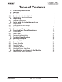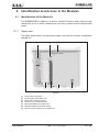
1
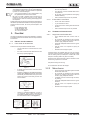
PJ300C-LCD User Manual Volume 1 Manufactured by Italy File Name: 03_PJ300C-LCD_ING_1.0.indd Version: 1.0 Date: 15/12/2006 Revision History Document History Date Version 15/12/06 1.0 Reason First Edition Editor J. H. Berti PJ300C-LCD - User Manual Version 1.0 © Copyright 2005 - 2006 R.V.R. Elettronica SpA Via del Fonditore 2/2c - 40138 - Bologna (Italia) Telephone: +39 051 6010506 Fax: +39 051 6011104 Email: [email protected] Web: www.rvr.it All rights reserved Printed and bound in Italy. No part of this manual may be reproduced, memorized or transmitted in any form or by any means, electronic or mechanic, including photocopying, recording or by any information storage and retrieval system, without written permission of the copyright owner. PJ300C-LCD Table of Contents 1. 2. 3. 3.1 3.2 4. 4.1 5. 5.1 5.2 5.3 5.4 6. 6.1 6.2 6.3 7. 8. 8.1 8.2 8.3 8.4 8.5 8.6 9. 9.1 Preliminary Instructions Warranty First Aid Treatment of electrical shocks Treatment of electrical Burns Unpacking General Description Quick guide for installation and use Preparation First power-on and setup Operation Management Firmware Front and Rear Panel Description Front Panel Rear Panel Connectors description Technical Specifications Working Principles Power supply Panel board Power Amplifier Control Board Telemetry board Interlock Output Interface Identification and Access to the Modules Identification of the Modules User Manual Rev. 1.0 - 15/12/06 1 1 2 2 2 3 3 5 5 7 10 11 19 19 20 21 22 23 23 23 23 24 24 24 25 25 PJ300C-LCD This page was intentionally left blank ii Rev. 1.0 - 15/12/06 User Manual PJ300C-LCD IMPORTANT The lightning flash with arrowhead, within a triangle, is intended to alert the user of the presence of dangerous voltage that may constitute a risk of electric shock. The exclamation point within an equilateral triangle is intended to alert the user to the presence of important operating and maintenance (servicing) instructions in the literature accompanying the equipment. 1. Preliminary Instructions WARNING: This equipment is fitted with earth connections both in the power cord and for the chassis. Make sure both are properly connected. • General Warnings Operation of this equipment in a residential area may cause radio interference, in which case the user may be required to take adequate measures. This equipment should only be operated, installed and maintained by “trained” or “qualified” personnel who are familiar with risks involved in working on electric and electronic circuits. “Trained” means personnel who have technical knowledge of equipment operation and who are responsible for their own safety and that of other unqualified personnel placed under their supervision when working on the equipment. “Qualified” means personnel who are trained in and experienced with equipment operation and who are responsible for their own safety and that of other unqualified personnel placed under their supervision when working on the equipment. The specifications and data contained herein are provided for information only and are subject to changes without prior notice. R.V.R. Elettronica SpA disclaims all warranties, express or implied.While R.V.R. Elettronica SpA attempts to provide accurate information, it cannot accept responsibility or liability for any errors or inaccuracies in this manual, including the products and the software described herein. R.V.R. Elettronica SpA reserves the right to make changes to equipment design and/or specifications and to this manual at any time without prior notice. WARNING: Residual voltage may be present inside the equipment even when the ON/OFF switch is set to Off. Before servicing the equipment, disconnect the power cord or switch off the main power panel and make sure the safety earth connection is connected. Some service situations may require inspecting the equipment with live circuits. Only trained and qualified personnel may work on the equipment live and shall be assisted by a trained person who shall keep ready to disconnect power supply at need. R.V.R. Elettronica SpA shall not be liable for injury to persons or damage to property resulting from improper use or operation by trained/untrained and qualified/unqualified persons. WARNING: The equipment is not water resistant. Any water entering the enclosure might impair proper operation. To prevent the risk of electrical shock or fire, do not expose this equipment to rain, dripping or moisture. Please observe local codes and fire prevention rules when installing and operating this equipment. WARNING: This equipment contains exposed live parts involving an electrical shock hazard. Always disconnect power supply before removing any covers or other parts of the equipment. Ventilation slits and holes are provided to ensure reliable operation and prevent overheating; do not obstruct or cover these slits. Do not obstruct the ventilation slits under any circumstances. The product must not be incorporated in a rack unless adequate ventilation is provided or the manufacturer’s instructions are followed closely. WA R N I N G : T h i s e q u i p m e n t c a n r a d i a t e radiofrequency energy and, if not installed in compliance with manual instructions and applicable regulations, may cause interference with radio communications. User Manual • Notice concerning product intended purpose and use limitations. This product is a radio transmitter suitable for frequencymodulation audio radio broadcasting. Its operating frequencies are not harmonised in designated user countries. Before operating this equipment, user must obtain a licence to use radio spectrum from the competent authority in the designated user country. Operating frequency, transmitter power and other characteristics of the transmission system are subject to restrictions as specified in the licence. 2. Warranty La R.V.R. Elettronica S.P.A. warrants this product to be free from defects in workmanship and its proper operation subject to the limitations set forth in the supplied Terms and Conditions. Please read the Terms and Conditions carefully, as purchase of the product or acceptance of the order acknowledgement imply acceptance of the Terms and Conditions. For the latest updated terms and conditions, please visit our web site at WWW.RVR.IT. The web site may be modified, removed or updated for any reason whatsoever without prior notice. The warranty will become null and void in the event the product enclosure is opened, the product is physically damaged, is repaired by unauthorised persons or is used for purposes other than its intended use, as well as in the event of improper use, unauthorised changes or neglect. In the event a defect is found, follow this procedure: 1 Contact the seller or distributor who sold the equipment; provide a description of the problem or malfunction for the event a quick fix is available. Sellers and Distributors can provide the necessary information to troubleshoot the most frequently encountered problems. Normally, Sellers and Distributors can offer a faster repair service than the Manufacturer would. Please note that Sellers can pinpoint problems due to wrong installation. 2 If your Seller cannot help you, contact R.V.R. Elettronica and describe the problem; if our staff deems it appropriate, you will receive an authorisation to return the equipment along with suitable instructions; 3 When you have received the authorisation, you may return the unit. Pack the unit carefully before shipment; use the original packaging whenever possible and seal the package perfectly. The customer bears all risks of loss (i.e., R.V.R. shall not be liable for loss or damage) until the package reaches the R.V.R. factory. For this Rev. 1.0 - 15/12/06 / 26 PJ300C-LCD reason, we recommend insuring the goods for their full value. Returns must be sent on a C.I.F. basis (PREPAID) to the address stated on the authorisation as specified by the R.V.R. Service Manager. Units returned without a return authorisation may be rejected and sent back to the sender. 4 Be sure to include a detailed report mentioning all problems you have found and copy of your original invoice (to show when the warranty period began) with the shipment. 3.1.2 Please send spare and warranty replacement parts orders to the address provided below. Make sure to specify equipment model and serial number, as well as part description and quantity. R.V.R. Elettronica SpA Via del Fonditore, 2/2c 40138 BOLOGNA ITALY Tel. +39 051 6010506 3. First Aid All personnel engaged in equipment installation, operation and maintenance must be familiar with first aid procedures and routines. 3.1 Electric shock treatment 3.1.1 If the victim is unconscious Lay the victim down on his/her back on a firm surface. • the neck and tilt the head backwards to free One rescuer: give 2 quick rescue breaths after each 15 compressions. • Two rescuers: one rescue breath after each 5 compressions. • Do not stop chest compressions while giving artificial breathing. • Call for medical help as soon as possible. If the victim is conscious • Cover victim with a blanket. • Try to reassure the victim. • Loosen the victim’s clothing and have him/her lie down. • Call for medical help as soon as possible. 3.2 Treatment of electric burns 3.2.1 Large burns and broken skin Follow the first aid procedures outlined below. • • • Cover affected area with a clean cloth or linen. • Do not break any blisters that have formed; remove any clothing or fabric that is stuck to the skin; apply adequate ointment. • Administer adequate treatment for the type of accident. • Get the victim to a hospital as quickly as possible. • Elevate arms and legs if injured. If medical help is not available within an hour, the victim is conscious and is not retching, administer a solution of table salt and baking soda (one teaspoon of table salt to half teaspoon of baking soda every 250 ml of water). the airway system (Figure 1). Have the victim slowly drink half a glass of solution for four times during a period of 15 minutes. Stop at the first sign of retching. Do not administer alcoholic beverages. Figure 1 • If needed, open the victim’s mouth and check for breathing. • If there is no breathing, start artificial respiration without delay (Figure 2) as follows: tilt the head backwards, pinch the nostrils, seal your mouth around the victim’s mouth and give four fast rescue breaths. 3.2.2 Minor burns • Apply cold (not ice cold) strips of gauze or dress wound with clean cloth. • Do not break any blisters that have formed; remove any clothing or fabric that is stuck to the skin; apply adequate ointment. • If needed, have the victim change into clean, dry clothing. • Administer adequate treatment for the type of accident. • Get the victim to a hospital as quickly as possible. • Elevate arms and legs if injured. Figure 2 • / 26 Check for heartbeat (Figure 3); if there is no heartbeat, begin chest compressions immediately (Figure 4) placing your hands in the centre of the victim’s chest (Figure 5). Figure 3 Figure 4 Figure 5 Rev. 1.0 - 15/12/06 User Manual PJ300C-LCD 4. Unpacking The package contains: 1 PJ300C-LCD 1 User Manual 1 Mains power cable The following accessories are also available from Your R.V.R. Dealer: • Accessories, spare parts and cables 4.1 General Description The PJ300C-LCD is an radio broadcasting amplifier manufactured by R.V.R. Elettronica SpA featuring adjustable RF power output up to 300 W under 50 Ohm standard load and less than 20W drive power requirement. The PJ300C-LCD has been designed for installation in a 19”x2HE box for rack. The amplifier incorporates a low-pass filter to keep harmonics below the limits provided for by international standards (CCIR, FCC or ETSI). Two major features of PJ300C-LCD are compact design and user-friendliness. Another key feature is its modular-concept design: the different functions are performed by modules with most connections achieved through male and female connectors or through flat cables terminated by connectors. This design facilitates maintenance and module replacement. The RF power section uses one MOSFET modulesable to deliver over 300W. An LCD on the front panel and a push-button panel provide for user interfacing with the microprocessor control system, which implements the following features: • Output power setup • Power output enable/disable • User-selectable threshold settings for output power alarm (Power Good feature) • Measurement and display of amplifier operating parameters • Communication with external devices, as programming systems or telemetry systems through RS232 or I2C serial interface Four LEDs on the front panel provide for machine status indication (ON, FAULT, FOLDBACK, RF MUTE). User Manual Rev. 1.0 - 15/12/06 / 26 PJ300C-LCD The amplifier management software is based on a menu system. User has four navigation buttons available to browse submenus: ESC, , , and ENTER. The rear panel features the mains input connectors, RF power input and output connectors, remote connector, protection fuse, interlock input and interlock output connectors and a BNC connector that provides an RF test point with level being 13 dBm ±6dB lower than power ouput. / 26 Rev. 1.0 - 15/12/06 User Manual PJ300C-LCD 5. Quick guide for installation and use This section provides a step-by-step description of the machine installation and configuration procedure. Follow these procedures closely upon first power-on and each time any change is made to general configuration, such as when a new transmission station is added or the exciter is replaced. Once the desired configuration has been set up, no more settings are required for normal operation; at each power-up (even after an accidental shutdown), the amplifier defaults to the parameters set during the initial configuration procedure. The topics covered in this section are discussed at greater length in the next sections, with detailed descriptions of all hardware and firmware features and capabilities. Please see the relevant sections for additional details. IMPORTANT: When configuring and testing the transmitter in which the amplifier is integrated, be sure to have the Final Test Table supplied with the machine ready at hand throughout the whole procedure; the Final Test Table lists all operating parameters as set and tested at the factory. 5.1 Preparation 5.1.1 Preliminary checks Unpack the amplifier and immediately inspect it for transport damage. Ensure that all connectors are in perfect condition. Provide for the following (applicable to operating tests and putting into service): √ Single-phase 230 VAC or 115 VAC (-15% / +10%) mains power supply with adequate ground connection √ FM exciter with adjustable output power up to 20W (as a minimum), like RVR Elettronica PTX30-LCD √ For operating tests only: dummy load with 50 Ohm impedance and adequate capacity (300 W as a minimum) √ Connection cable kit including: • Mains power cable • Coaxial cable with BNC connectors for interlock signal connection between exciter and amplifier • RF connection cable between exciter and amplifier (50 Ohm coaxial cable with “N”-type connectors) • RF cable for output to load / antenna (50 Ohm coaxial cable with 7/8” connectors as standard, or optional 7/16” connectors) User Manual Rev. 1.0 - 15/12/06 / 26 PJ300C-LCD 5.1.2 Mains power supply WARNING: Disconnect mains power supply before beginning these procedures. The supply unit (please see chapter 8.1 for a detailed description) is equipped with fuse. The mains power supply protection fuse are conveniently located on the rear panel and are easily accessed (see figure 6.2): to check or replace a fuse, disconnect machine from power mains, unscrew fuse cover and pull fuse out of socket. The following fuses are used: Main Fuse (fig. 6.2 – item [9]) @ 230 Vac @ 115 Vac 8A-T type 5x20 8A-T type 5x20 Table 5.1: Fuse The main power supply unit is the full-range type and requires no voltage setup. 5.1.3 Connections Connect the output of a suitable FM exciter (for instance, PTX30-LCD exciter available from R.V.R. Elettronica) to the RF input (see figure 6.2) using a 50-Ohm coaxial cable with “N”-type connectors. To begin with, set exciter to minimum output power and switch if off. Connect the amplifier INTERLOCK OUT output (figure 6.2) to the matching INTERLOCK IN input fitted on all R.V.R. Elettronica exciters as standard; if your exciter is a different brand, identify an equivalent input. Connect the RF output (see figure 6.2) to an adequately rated dummy load or to the antenna. WARNING: Electric shock hazard. Never handle the RF output connector when the machine is powered on and no load is connected. Injury or death may result. Ensure that the POWER switch on the front panel is set to “OFF”. Connect the mains power cable to the MAINS terminal board on the rear panel (see figure 6.2). / 26 Rev. 1.0 - 15/12/06 User Manual PJ300C-LCD Note : The mains must be equipped with adequate ground connection properly connected to the machine. This is a pre-requisite for ensuring operator safety and correct operation. WARNING: The power supply connector is a terminal board. Ensure the wire is not live before performing the connection. Please see figure 5.2 for a hook-up diagram showing RF connection between amplifier and exciter and load connection. Figure 5.2: Connection to exciter 5.2 First power-on and setup Follow this procedure upon first power-on and after making changes to the configuration of the transmitter in which the amplifier is integrated. Note : Standard factory settings are RF power output Off (Pwr OFF) and output power set to upper limit (unless otherwise specified by customer). 5.1.2 Pilot exciter setup Set up the pilot exciter so that the output power it delivers to a matched load equals the maximum input power indicated in the amplifier final test table, switch off the exciter and connect it to the amplifier. User Manual Rev. 1.0 - 15/12/06 / 26 PJ300C-LCD 5.2.2 Power-on When you have performed all of the connections described in the previous paragraph, power on the amplifier using the suitable power switch on the front panel (figure 6.1). Power on the pilot exciter. 5.2.3 Power check Ensure that the ON light turns on (see figure 6.1). Machine name should appear briefly on the display, quickly followed by forward and reflected power readings (figure 5.2 - menu 1). If RF output is disabled, these readings will be zero. 5.2.4 How to enable Local mode and RF output Check current mode setting and enable Local mode (if not already enabled) following menu path Fnc ⇒ Loc ⇒ Local (figure 5.2): if left disabled, the machine will not accept the next commands. Check current RF output setting and enable output (if not already enabled) following menu path Fnc ⇒ Pwr ⇒ ON (figure 5.2 - menu 4). Check output power level and set to maximum level (if not already set to maximum) from the Power Setup Menu, which you can call up by pressing these keys in the order: ESC (opens Default Menu) ⇒ ENTER (hold down for 2 seconds) ⇒ SET ⇒ use key to set bar to maximum limit (figure 5.2 - menu 2). 5.2.5 Input power check and setup Go to Pwr menu (figure 5.2 - menu 5) and look up forward output power Fwd, reflected power Rfl and input power Inp readings. With drive power set as specified in the Final Test Table, amplifier output power should be 300W or higher: if needed, fine tune drive power until achieving rated output power. Never exceed 330W output power. Note : Normally, drive power should not exceed 20W (typically 15W): higher drive power requirements are a symptom of abnormal operation. / 26 WARNING: Drive power levels above 20W (typically 25W), result in exceeding input power, which causes a temporary amplifier lock-out (see section 5.3.4.1 - Alarms and Faults for more details). Rev. 1.0 - 15/12/06 User Manual PJ300C-LCD 5.2.6 RF output power level control IMPORTANT: The amplifier incorporates Automatic Gain Control and output power is modulated based on the power level set by the user and actual operating conditions, such as temperature, reflected power and other parameters. Drive power must be kept steady at maximum output power capacity. Please read section 5.3 for more details of RF power modulation. Open the Power setup menu (figure 5.2 - menu 2) pressing the following keys in the order: ESC (opens Default Menu) ⇒ ENTER (hold down for 2 seconds) Use SET menu and keys to set the desired amplifier output power; the SET bar at the side provides a graphic display of set power, whereas the forward power value shown on the display (Fwd: xxxx W) gives actual output power reading, and may be lower than set power if an Automatic Gain Control is in limitedpower mode (please read section 5.3 concerning RF power modulation for more details”. Note : Output power can also be set in a Pwr OFF condition; in this condition, (Fwd) output power reading on the display will be 0 (zero), whereas the SET bar, which you can control using the keys, provides a graphic display of the amount of power that will be delivered the moment you switch back to Pwr ON state. 5.2.7 Changing the Power Good alarm threshold Change Forward Power Good alarm setting PgD from the Fnc menu as required (factory setting is 50%). Please read section 5.3.1 for more details. 5.2.8 Changing machine I2C address Change the IIC address in the Mix menu as required (factory setting is 01). Please read section 5.3.5 for more details. 5.2.9 How to enable Remote mode If you wish to use the telemetry control feature, enable Remote control in the Fnc menu (see section 5.3.1 for details). Note : In the Remote mode, all local push-button controls except Remote/Local (for switching back to Local mode) are disabled . Operating parameter readings are available. User Manual Rev. 1.0 - 15/12/06 / 26 PJ300C-LCD 5.3 Operation 1) Power on the amplifier (chap. 6.1) and ensure that the ON light turns on (chap. 6.1). Machine name should appear briefly on the display, quickly followed by forward and reflected power readings (Menu 1), provided that the amplifier is delivering output power. Menu 1 1b) To modify power level setting, hold down the ENTER button until opening the power setup menu. The edit screen will look like this: Menu 2 Next to SET indication, a bar provides a graphic display of preset output power. The filled portion of the bar is proportional to set power level. Example 100% output power Full bar ≅ 300W in output 50% output power Half bar ≅ 150W in output 25% output power 1/4 bar ≅ 75W in output The bottom line provides instantaneous power reading (297W in this instance); press button to increase level, press to decrease it. When you have achieved the desired level, press ENTER to confirm and exit the default menu. Please note that the setting is stored automatically; in other words, if you press ESC or do not press any keys before the preset time times out, the latest power level set will be retained. NOTE: This feature prevents the machine from delivering maximum power as soon as output is enabled from menu 4, or in the event the machine is already set to ON and energised. 2) Ensure that machine is not in a locked-out state. Press the ESC key (chap. 6.1) to call up the selection screen (Menu 3). Highlight Fnc and press ENTER 10 / 26 Rev. 1.0 - 15/12/06 User Manual PJ300C-LCD to confirm (chap. 6.1) and access the appropriate menu (menu 4). If LOC is set to REMOTE (machine remote control), move cursor to LOC and press ENTER (chap. 6.1); label will change to LOCAL, i.e. local control operation mode. In the same menu, ensure that power limiting is disabled: if PWR is set to OFF, i.e. power output is disabled, move cursor to PWR. Press ENTER (chap. 6.1 - [9]) and label will switch to ON, i.e. power output enabled. Press ESC (chap. 6.1) twice to go back to the default menu (menu 1). 3) Fine tune power setting from menu 2 (see description of item 1b) until achieving the desired value. WARNING: Machine is capable of delivering more than rated output power (300 W); however, never exceed the specified power rating. NOTE: Exciter drive power setting should never exceed 20W, or it will trigger an Overdrive Alarm. NOTE: If power is set to 0 W in the edit mode, the INTERLOCK OUT contact (chap. 6.2) trips and external exciter power is immediately inhibited. Next, you can review all operating parameters of the machine through the management firmware. Normally, the machine can run unattended. Any alarm condition is handled automatically by the safety system or is signalled by the LED indicators on the panel or by display messages. NOTE: Standard factory settings are: output power set to upper limit (unless otherwise specified by customer) and OFF. 5.4 Management Firmware The machine features an LCD with two lines by 16 characters that displays a set of menus. Figure 5.2 below provides an overview of machine menus. The symbols listed below appear in the left portion of the display as appropriate: (Cursor) - Highlights selected (i.e. accessible) menu. (Filled arrow) - Editable parameter marker. This symbol appears in menus that take up more than two lines to aid browsing. (Three empty arrows) - Parameter is being edited. (Empty arrow) - Current line marker; the parameter in this line cannot be edited. This symbol appears in menus that take up more than two lines to aid browsing. User Manual Rev. 1.0 - 15/12/06 11 / 26 PJ300C-LCD Menu Menu 22 Menu Menu 11 Default Menu Power Setup Menu Menu Menu 33 Selection Screen Menu Menu 44 Operation Menu Menu Menu 55 Power Menu Menu Menu 66 P.A. Menu Menu Menu 77 Alarm Menu Menu Menu 88 Miscellaneous menu Menu Menu 99 Version Menu Figure 5.2 When the display is off, touching any key will turn on backlighting. When the display is on, pressing the ESC button (chap. 6.1) from the default menu (menu 1) calls up the selection screen (menu 3), which gives access to all other menus: Menu 3 To gain access to a submenu, select menu name (name is highlighted by cursor) using button or and press the ENTER button (chap. 6.1). Press ESC again (chap. 6.1) to return to the default menu (menu 1). 12 / 26 Rev. 1.0 - 15/12/06 User Manual PJ300C-LCD 5.4.1 Operation Menu (Fnc) In this menu, you can set power output On/Off, toggle between “Local” or “Remote” control mode and set the Forward Power Good (PgD) threshold rate. To edit an item, highlight the appropriate line using the UP and DOWN buttons and then press and hold the ENTER button (chap. 6.1) until the command is accepted. This way, Pwr setting is toggled between On and Off and Mod setting is toggled between “x1” and “x10”. To edit the Power Good rate, simply select item “PgD” and edit its value using buttons and ; finally, press ENTER to confirm (chap. 6.1). Menu 4 Pwr Enables (ON) or disables (OFF) amplifier power output. Loc Modifies machine operation. In the LOCAL mode, the machine can read and modify its operating parameters through the navigation keys and the management firmware, whereas all other sources are locked out. In the REMOTE mode, the machine can only read its operating parameters; parameters are modified based on the commands received from other connected telemetry systems. PgD Modifies Power Good (forward power) threshold. The Power Good rate is a percent of machine rated power (300 W), not of forward output power. This means that this threshold set at 50% will give 150 W regardless of set power level. The Power Good feature enables output power control and reporting. When output power drops below set Power Good threshold, the machine changes the state of pin [7] of the DB15 “Remote” connector located on the rear panel (figure 6.3.2 - [6]). 5.4.2 Power Menu (Pwr) This screen holds all readings related to machine output power: Menu 5 Fwd Rfl Inp User Manual Forward power reading. Reflected power reading. Input power reading. Rev. 1.0 - 15/12/06 13 / 26 PJ300C-LCD Note that these are readings, rather than settings, and cannot be edited (note the empty arrow). To change power setting, go to the default menu (menu 1) as outlined earlier. 5.4.3 Power Amplifier (P.A) Menu This screen is made up of four lines that can be scrolled using the buttons , shows the readings relating to final power stage: and Menu 6 Note that these are readings, rather than settings, and cannot be edited (note the empty arrow). VPA IPA Voltage supplied to amplifier module. Current absorbed to amplifier module. Eff Efficiency based on ratio of forward power to amplifier module power in percent ( FWD PWR/(Vpa x Ipa) % ). Tmp Machine internal temperature. 5.4.4 Alarm Menu (Alm) This menu shows any alarm conditions occurring during machine operation. Alarm thresholds are preset at the factory. Menu 7 FWD RFL INP Counter of alarm conditions triggered by forward power. Counter of alarm conditions triggered by reflected power. Counter of alarm conditions triggered by input power. Reset Alm Alarm counter reset. 14 / 26 Rev. 1.0 - 15/12/06 User Manual PJ300C-LCD Alarm conditions are numbered from 1 to 10 and reflect the following situations: forward output power too high, reflected output power too high and input power too high. Alarm monitoring cycle is as follows: when an alarm condition is detected, alarm counter increases by 1 unit, machine goes into lock-out state and the display shows the cause for the stop (chap. 5.3.4.1). After 15 seconds, the machine attempts to re-start; if a new alarm condition is detected, cycle is repeated over and over again up to 10 times maximum. If machine re-starts successfully, all alarm counters are reset after 30 minutes’ regular operation. After 10 alarm conditions triggered by the same cause, the machine goes into fault lock-out mode, a lock-out mode warning appears on the display and the “FAULT” LED turns on (chap. 6.1). After the alarm condition has been rectified, the counter can be reset by highlighting “Reset Alm” and holding down the ENTER key for some time (chap. 6.1). 5.4.4.1 Alarms and Faults There are three types of alarms that can cause a machine lock-out and trigger a “FAULT/LOCK” indication. When any one of the three alarm thresholds is exceeded, the system will automatically switch to the warning screen (even though the user is browsing system menus) and the following messages are displayed: 1. Over Forward Power Forward power threshold exceeded. Alarm 1 2. Over Reflected Power Reflected power threshold exceeded. Alarm 2 3. Over Input Power Input power threshold exceeded. User Manual Rev. 1.0 - 15/12/06 15 / 26 PJ300C-LCD Alarm 3 Monitoring cycle is as follows: • An alarm condition occurs; • Alarm is displayed and device is locked out for 15 sec.; • Operating conditions are restored; • Verification. Upon reaching the 10 cycle limit, a “FAULT” indication is triggered and the device goes into lock-out mode; the appropriate LED turns on (figure 6.1) and this screen is displayed: I. Over Forward Power Forward power alarm display. Stop 1 II. Over Reflected Power Reflected power alarm display. Stop 2 III.Over Input Power Input power alarm display. Stop 3 16 / 26 Rev. 1.0 - 15/12/06 User Manual PJ300C-LCD Once the machine goes into “FAULT” mode, it will no longer attempt to re-start; choose the appropriate reset procedure according to current machine setting: • Machine set to LOCAL control mode - press “Reset Alm” in the alarm menu (menu 7) or power off and back on again using the POWER switch (chap. 6.2). • Machine set to REMOTE control mode - power off and back on again sending the appropriate command via the DB15 connector (chap. 6.3.2 - item [14] and [15]). There is a fourth alarm that does not trigger a “FAULT” condition, but allows some time until correct operating conditions are restored. When the temperature alarm threshold is exceed (about 85°C), the following screen appears: 4. Over Temperature Temperature power threshold exceeded. Alarm 4 5.4.5 Miscellaneous Menu (Mix) This menu lets you set machine address in an I2C bus serial connection: Menu 8 IIC I2C address setting. The I2C network address becomes significant when the exciter is connected in an RVR transmission system that uses this protocol. Do not change it unless strictly required. 5.4.6 Version Menu (Vrs) This screen holds machine version/release information: Menu 9 User Manual Rev. 1.0 - 15/12/06 17 / 26 PJ300C-LCD Note that these are readings, rather than settings, and cannot be edited (note the empty arrow). Rel Dat Tab 18 / 26 Firmware release information. Release date. Shows table loaded in the memory. Rev. 1.0 - 15/12/06 User Manual PJ300C-LCD 6. Front and Rear Panel Description This section describes the components found on the front and rear panel of PJ300C-LCD. 6.1 Front Panel 1 2 3 4 5 6 7 8 9 10 11 12 Figure 6.1 [1] AIR FLOW [2] ON [3] FAULT [4] FOLDBACK [5] R.F. MUTE [6] CONTRAST [7] ESC [8] [9] [10] ENTER [10] DISPLAY [11] POWER User Manual Air flow for the forced ventilation. Green LED - Turns on when amplifier is powered on. Red LED - Turns on when machine is in permanent fault lock-out mode. Yellow LED - Turns on when foldback current limiting (Automatic Gain Control) is intervened. Yellow LED - Turns on when exciter power output is inhibited by an external interlock signal. Display contrast trimmer. Press this button to exit a menu. Navigation button used to browse menu system and edit parameters. Navigation button used to browse menu system and edit parameters. Press this button to confirm a modified parameter and open a menu. Liquid Crystal Display AC mains ON/OFF switch. Rev. 1.0 - 15/12/06 19 / 26 PJ300C-LCD 6.2 Rear Panel 1 2 9 3 10 4 5 6 7 11 12 8 13 14 15 16 Figure 6.2 [1] [2] [3] [4] PLUG FAN R.F. OUTPUT INTERLOCK IN [5] EXT AGC [6] REMOTE [7] GSM ANT [8] REMOTE [9] FUSE BLOCK [10]R.F. TEST [11]24VDC IN [12]SERVICE [13]INPUT PWR [14]INTERLOCK OUT [15]INTERLOCK IN [16]FOLDBACK 1-2 20 / 26 Mains supply plug, 90 - 260V 50-60 Hz. Fan for the forced ventilation of the amplifier. RF output connector, N-type, 50Ω. Interlock input BNC connector: when central conductor is connected to ground, the transmitter is placed into forced standby mode. Trimmer for the control of the delivered power in function of the FWD fold input (FWD EXT AGC) and RFL fold input (RFL FOLD AGC). DB15 connector for telemetry of the machine. Reserved for Future Uses - SMA connector for GSM Antenna. Reserved for Future Uses - DB25 connector for telemetry of the machine. Fuse carrier. Use a screwdriver to access the fuse. Contains the general protection fuse rated 8AT 5x20. RF test output, approx. 13 dBm wrt the RF output power level Not Used - External 24Vdc supply input. Negative (black) and Positive (red). DB9 connector for interconnection with other devices and for factory parameters programming (only for factory programming) RF input connector, N-type, 50Ω. Interlock output BNC connector: when the transmitter goes into stand-by mode, the (normally floating) central connector is connected to ground. Reserved for Future Uses - Interlock input BNC connector: Reserved for Future Uses - Trimmer for the control of the delivered power in function of the foldback inputs Rev. 1.0 - 15/12/06 User Manual PJ300C-LCD 6.3 Connectors description 6.3.1 Service (for factory setting purposes only) Type: Female DB9 1 2 3 4 5 6 7 8 9 NC TX_D RX_D Internally connected to 6 GND Internally connected to 4 Internally connected to 8 Internally connected to 7 NC 6.3.2 Remote Type: Female DB15 Pin Name Type 1 Interlock IN 2 Ext AGC FWD IN 3 GND 4 SDA IIC I/O 5 VPA Tlm ANL OUT 6 FWD Tlm ANL OUT 7 Power Good DIG OUT 8 GND 9 GND 10 Ext AGC RFL IN 11 SCL IIC I/O 12 IPA Tlm ANL OUT 13 RFL Tlm ANL OUT 14 On cmd DIG IN 15 OFF cmd DIG IN User Manual Purpose Inhibits power if closed to GND Ext. signal,1-12V, for power limitation (AGC) Ground Serial for IIC communication PA supply voltage: 3.9V F.S. Forward power: 3.9V F.S. Signalling of the activation by the grounding of the contact normally open (chap. 5.4.1) Ground Ground Ext. signal,1-12V, for power limitation (AGC) Clock for IIC communication PA power supply: 3.9V F.S. Forward power: 3.9V F.S. A pulse towards ground (500 ms) triggers power output A pulse to ground (500 ms) inhibits power output Rev. 1.0 - 15/12/06 21 / 26 PJ300C-LCD 7. Technical Specifications Parameters GENERALS Frequency range Rated output power Input power for rated output Power supply type AC Supply Voltage DC Supply Voltage AC Apparent Power Consumption Active Power Consumption RF Fan active Power consumption RF module efficiency Overall efficiency Input device Display Overall Phisical Dimensions Ambient working temperature Spurious & harmonic suppression Conditions U.M. MHz W W Mains input voltage range CPU backup Input Voltage Front panel width Front panel height Overall depth VAC VDC VA W W % % mm HE mm °C dBc PJ300C-LCD 87.5 ÷ 108 300 10 Mono phase 230 ±15% 540 500 13 65 58 4 pushbutton Alphanumerical LCD - 2 x 16 483 2 370 0 to + 50 (operational -10) >70 (75 typical) (*) macchina in compressione input 18W (*) macchina in compressione input 18W (*) macchina in compressione input 18W (*) macchina in compressione input 18W Meets or exceeds all FCC and CCIR rules RF INPUT RF Input Driver power for rated output Connector Impedance Max input power before protection Ohm W N type 50 11 W 20 RF OUTPUTS RF Output Connector Impedance Ohm Connector RF Monitor Impedance Output Level Ohm dB N female type 50 BNC 50 13 +\-6 dBm Referred to the RF output BNC BNC For remote power inhibition (short is RF off) For remote power inhibition (short is RF off) DB9 F Factory reserved for firmware program DB15F IIC + 5 analog / digital inputs, 5 analog / digital outputs AUXILIARY CONNECTIONS Interlock Input Interlock Output RS232 Serial Interface Service I2Cbus Modem RS485 Serial Interface Remote Interface Telemetry Interface Connector Connector Connector Connector Connector Connector Connector Connector Connector POWER REQUIREMENTS AC Power Input AC Supply Voltage VAC 115 / 230 ±15% AC Apparent Power Consumption VA W 540 500 0,93 VDE male Active Power Consumption Power Factor Connector DC Power Input DC Supply Voltage DC Current VDC ADC FUSES On Mains On services On PA Supply On Aux VDE socket 1 External fuse F 8 T - 5x20 mm MECHANICAL DIMENSIONS Front panel width Phisical Dimensions Front panel height Overall depth Chassis depth Weigh mm mm mm mm kg 483 (19") 88(xxx") 390 370 (xxxx) about 6 19" EIA rack FWD fold REF fold RF ON RF OFF Interlock FWD REF VPA IPA Power Good I2Cbus For P.A. A.G.C. purpose, min 0,5 Vcc For P.A. A.G.C. purpose, min 0,5 Vcc OPTIONS Telemetry code code code code 115 Vac TELEMETRY / TELECONTROL Analogical level Analogical level Remote connector inputs pulse pulse ON/OFF level Analogical level Analogical level Remote connector outputs Analogical level Analogical level ON / OFF level Remote connector others for remote power inhibition (short is RF off) max 5 Vcc max 5 Vcc max 5 Vcc max 5 Vcc open collector TELEMETRY-TELECONTROL SW Telecon Yes, via TLC300 or TLC2000 VARIOUS Cooling type Acoustic Noise dBA Forced, with internal fan <75 Leq 3 min @ 1 m STANDARD COMPLIANCE Safety EMC Spectrum Optimization 22 / 26 Rev. 1.0 - 15/12/06 User Manual PJ300C-LCD 8. Working Principles 8.1 Power Supply The PJ300C-LCD power supply unit is a switching-type unit whose +50 V main output powers the machine’s RF amplifier. The power supply also features stabilizers for generating continuous +5 V and +18 V voltages for supplying the other equipment circuits. Note that the power supply is a “direct from mains” type, or rather it is without a transformer, and it can be connected to any voltage between 90 and 260 V without any adjustments or manual settings. 8.2 Panel board The panel board accommodates the microcontroller that runs the machine control software and all user interface elements (display, LED’s, keys, …). This board is interfaced with other machine modules via flat cables and provides for power supply, control signals and measurement distribution. 8.3 Power Amplifier The final power stage is enclosed in a totally shielded metal container fixed to the central part of the device. The RF signal coming from the main board reached the pilot, it come amplified and sent to the final stage which takes care of final amplification up to 300W. The amplifier is made with one SD2942 and one attenuator of 6dB 50W. In addiction to the actual RF amplification, this circuit carries out the following functions: • Control of the power level in output, depending on the setting • Reduction of the power supplied when in presence of high-level reflected power • Measure of the input power (ensemble the control board) • Measure of the forward and reflected power by means of directional couplers • Measure of the current absorbed by the power amplifier • Measure of the temperature • Low-pass filtering of the RF signal in output This board also features an RF sampling of approximately 13dBm ±6dBm RF with respect to the output, which is available on a BNC connector below the transmitter output connector. This sample is is useful for verifying the characteristics of the carrier, but not for verifying those of the upper harmonics. User Manual Rev. 1.0 - 15/12/06 23 / 26 PJ300C-LCD 8.4 Control Board The main function of this board is to check and correct the MOSFET polarization voltage of the RF amplifier section. It also provides the measurement of the absorbed current and contains a circuit for signaling power supply unit faults. If no alarms are present, the voltage is adjusted only depending on the set output power, with a feedback mechanism based on the reading of the power really delivered (AGC). The voltage is also affected by other factors, such as: • Excess of reflected power. • External AGC signals (Ext. AGC FWD, Ext. AGC RFL). • Excess of temperature. • Excess of absorbed current from the RF module. 8.5 Telemetry board This board is designed to inform the user of the equipment operation state. All input and output signals are available on the DB15 connector. The same board also features the “INTERLOCK” BNC connector for disabling the device. By grounding the central pin, the output power is reduced to zero until the connection is removed. When an R.V.R. amplifier is used, this connector is linked to the power amplifier REMOTE or INTERLOCK by means of a BNC-BNC connection. In case of amplifier faults, the central conductor is grounded thus forcing the machine to enter in stand-by mode. 8.6 Interlock Output Interface The interlock output interface serves to generate the signal of INTERLOCK OUT, on the board is present one jumper which if set in opposite way reveres the working logic. 24 / 26 Rev. 1.0 - 15/12/06 User Manual PJ300C-LCD 9. Identification and Access to the Modules 9.1 Identification of the Modules The PJ300C-LCD is made up of various modules linked to each other through connectors so as to make maintenance and any required module replacement easier. 9.1.1 Upper view The figure below shows the equipment upper view with the various components pointed out. 1 2 4 3 5 6 7 figure 9.1 [1] [2] [3] [4] [5] [6] [7] User Manual Power Supply (PSL600) Control Board (SL045DR1101) Panel Board (SL007PC2002) Cooling Fan (VTL9G824G102) RF Module Board (SL123RF1001) Telemetry Board (SLTLMTXLCD03) Interlock Output Interface (SL123IN1001) Rev. 1.0 - 15/12/06 25 / 26 PJ300C-LCD This page was intentionally left blank 26 / 26 Rev. 1.0 - 15/12/06 User Manual