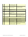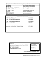
1
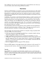
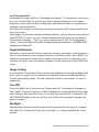
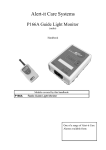
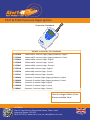
P137 & P138 Plesiocare Pager system
Supervisor Handbook
Models covered by this handbook
P 137AAA
Advanced 32 monitor Pager (legacy products): English
P 137AAB
Advanced 32 monitor Pager (legacy products): French
P 137BAA
Advanced 64 monitor Pager: English
P 137BAB
Advanced 64 monitor Pager: French
P 137BAC
Advanced 64 monitor Pager: German
P 137CAA
Advanced 8 monitor Pager: English
P 137CAB
Advanced 8 monitor Pager: French
P 137CAC
Advanced 8 monitor Pager: German
P 138AAA
Domestic 3 monitor Pager (legacy products): English
P 138AAB
Domestic 3 monitor Pager (legacy products): French
P 138BAA
Domestic 3 monitor Pager: English
P 138BAB
Domestic 3 monitor Pager: French
P 138BAC
Domestic 3 monitor Pager: German
One of a range of Alert-it Care
Alarms available from:
UH1068A
Alert-it Care Alarms, Atherstone House, Merry Lees
Industrial Estate, LE9 9FE
0845 2179951, www.alert-it.co.uk, [email protected]
Made in the
UK
This handbook is for the use of a manager who is responsible for care alarm system as a whole, rather than setting individual monitors
Overview
The Alert-it P137/8 Pager is a powerful system monitoring device for radio linked
alarm systems. It can receive status transmissions from up to 64 alarm monitors
(depending on model) and alerts the user should any enter an alarm condition.
The alarms are classified into 4 levels and the alarm display is prioritized in terms
of level and age.
In addition, any monitor can be deemed of high integrity, in which case the user is
alerted if the radio link to that monitor fails. This is achieved by monitoring a
heartbeat signal that is sent approximately every 8 seconds from such monitors.
Lastly, any monitor can be additionally set to detect the transmitter moving
outside a pre-defined geographical area. This is achieved by calibrating the
minimum acceptable radio signal strength from the monitor, and if it falls below
this value then the user is alerted.
For convenience to the user each monitor can be named to suit the application
and each level of alarm plays a different “tune”. The pager can also be used in
discrete mode with a vibrator, as may be preferred for night use.
The P137 pager can send all alarm details to a computer using an optional USB
interface (P146). This link also allows:
Ÿ all the user data to be saved and reloaded from a computer (eg for cloning
replacement pagers) using P172C software
Ÿ triggering additional equipment such as telephone autodiallers or sirens.
Ÿ reading the P137 pager log of both the frequency of alarms from each monitor
and the maximum time to service those alarms, using the P172B logging
software. This provides essential metrics for any manager to demonstrate the
level of response achieved.
Ÿ Real-time logging of alarms using the P172A software
The term NODE appears in the pager display and is reference in this manual. It is
synonymous with monitor, referring to any device that can generate an alarm
Operation
Turn On
Press MENU for 3 seconds and the display should come on and show the
PRODUCT name followed by 4 digits for the software Version/Issue and 4 digits for
a special checksum that allows the manufacturer to offer unique installation codes.
The normal code is 07A6
UH1068A P137 Supervisor Manual page 2 of 13
19/02/2015 11:22:01 AM
First Time Operation
As shipped the pager will be in “Extended User Mode”. The Supervisor can restrict
the user functionality as well as use more advance features of the pager,
especially concerned with the Configuration and Administration of systems and
computer communications.
The Supervisor mode is enabled by entering a password when required within the
menu structure.
If the pager has not been configured before delivery, then at the first time of using
the EDIT/SET-UP menu the user will be prompted to start entering new monitor
information manually. There are many alternatives to this for configuring a
system, so for full details of System Configuration see handbook “UH1068C P137
Configuration Manual”
Unpaired Monitors
Normally a care home will have all monitors paired to the pagers used. However if
this is not the case then any unpaired monitors will flash up the name “NEW!” followed by 4 characters which can be used to trace the source. To prevent a nuisance to the carers, then this display (ViewAll) can be turned off in the FUNCTION
menu
Range Testing
It is essential to check that all the monitors are capable of reaching the pager with
their radio. In health critical situations the Safelink radio should be operated in
Failsafe (Securelink) mode. See the individual monitor instructions on how to
enable this.
Turn Off
Press the MENU for 3 seconds until “Setup and Edit” is displayed, followed by
“User Mode”. Press the right key. If the Extended User mode is disabled then enter
the password. The next menu item is Turn Off. Press the SELECT (up) button.. DO
NOT REMOVE batteries to turn off the unit as this will eventually damage the
battery contact
Backlight
The Backlight automatically illuminates for 15 seconds after an alarm is received
and again for 15 seconds if any key is pressed. It is always enabled for menu
modes.
UH1068A P137 Supervisor Manual page 3 of 13
RF Tune
Full Menu Structure
UH1068A P137 Supervisor Manual page 4 of 13
19/02/2015 11:22:01 AM
Details of Menu Features
Standby Operation
1
Enter “Set-up & Edit”
After pressing MENU for 3
seconds
See next Main Menu table
2
Snooze & View
Press SELect to silence any
alarm for 5 minutes
Left/right will now list all active alarms.
MENU returns to standby
Changes main user operating
features.
eg Light, Sound and Vibration
See 1.21.1below
1. Main Menu
1.1
USERmode
1.2
TurnOff
Turns off the pager
Restart be pressing MENU key 3
seconds
1.3
ResetAll
Resets all alarms
They will be reactivated if the node is
still transmitting an alarm message
1.4
List
Lists all the nodes with access
to a sub-menu of features
see 1.2.1. below
1.5
AddNode
Add a node manually (with
address/type/failsafe/name)
Enter Address, Type, Failsafe on/off and
rename
1.6
AutoAdd
Nodes are added
automatically when a
transmission is received
After each addtion, edit node name and
enable process for the next one
Password (bypassed for Extended Users)
Password
1.7
Function
Enables & Disables features
See 1.7.1 below
1.8
Data Programming
Enables the pager to be
upgraded (Flash) or the node
information to be overwritten
(User Data)
used with the P146 USB Interface
1.9
Set Pass
Set Supervisor password
Default 1900 (see manufacturer for
P138)
1.1
User_mode sub-menu
Sub menus from above main menu items follow
Light
Turns backlight on/off
Discrete
Switches tunes & vibrate
Key beep
Silences the beep on key press
Password (bypassed for Extended Users)
RF Tune
Enables tune for RF Fail Alarms Useful to silence alarm if equipment
node off
Silent
Sound & Vibrate off
PTO
UH1068A P137 Supervisor Manual page 5 of 13
1.2
List
Scroll left & right through the
list of nodes and press up to
select one for detailed menu
Property
Only supervisor can
edit by entering
password in main
menu
Shows node address/type &
status. Select No to manually
edit values if allowed.
Rename
The node name can be
changed
Also shows:
W= Wander mode enabled
F= Failsafe mode enabled
Password
1.7
Wander
The wander mode can be
Reset (turned off),
Automatically set Manually
Adjusted.
See configuration manual for full details.
Program Unit
Current node setting sent to a
connected module to clone it.
Connect lead to transmitter module
first. Press YES to complete action. If
successful “SAVING” displayed and
returns to LIST menu.
Delete
Delete the current node
Confirm to activate delete
ON: Show transmissions, even
if NOT registered to this pager
OFF: Show only registered monitors (ie
NEW! Is suppressed)
Function sub-menu
ViewAll
UserExt
Allow user extended functions
Events
When off some fault codes are These codes have special application in
hidden from the carer
logging movement only
Node test
Shows precise information
about the node radio strength
and frequency. The USB port
also logs all the node packet
details at each transmission.
UH1068A P137 Supervisor Manual page 6 of 13
For engineer use in system checking.
Automatically reenables ViewAll. N.B.
Alarms are NOT shown in this mode just
the signal quality
19/02/2015 11:22:01 AM
Overview of Functionality
Basic User Mode
1. Listing all registered (or new) monitors. If a monitor is selected, then the basic
user can only view (not edit) the monitor properties.
2. Setting the USERmode for such items such as playing tunes, key beep, vibrator on/off, backlight on/off
3 SNOOZE, which silences alarms for 5 minutes and shows all the active alarms
in a list
Extended User Mode
The supervisor is able to allow the user a greater level of control (see?). In this
case the basic user menu mode extends to cover
1. Turning the pager off
2. Resetting alarms manually (rather than only via resetting the transmitter).
Warning: If the alarm is reset manually then the statistics of time to respond
is considered not valid for this alarm and the time value is not therefore stored.
Note: If the transmitter is not reset then the alarm maybe be re-transmitted
every 8 seconds, which will re-activate any alarms.
Supervisor Functions
The supervisor mode is enabled by entering the correct 4 digit password when requested. The default password is 1900. This extends the menu to cover:
1.
2.
3.
4.
5.
6.
7.
8.
8.
Adding monitors
Deleting monitors
Auto-registration of monitors
Enabling the extended user capability.
Setting the operating environment for the user
Enabling more advanced system monitor functions
Resetting the password
Programming monitors with monitor address/type
Enabling re-programming of the pager data or software from a computer
Node Property Edit
The Supervisor can adjust the Address/Type/Name and Failsafe Operation of each node
from the LIST/PROPERTY menu, BUT the password must be entered in the first menu level
first (ie after entering Setup&Edit scroll right until the PASSWORD is requested, now go
back to LIST and edit if required.
UH1068A P137 Supervisor Manual page 7 of 13
Familiarise yourself with the basic editing/navigation
process
Hold down 3 sec to enter Set-Up & Edit menus. Press to abort menus, one level at a time. Also used to scroll through numbers & letters if required.
Scroll back & forth though menus or s elect settings shown on the display
above the key
Press to display list of active alarms. In menu mode also used to scroll through
numbers & letters or select an option,
Example edit screens
Scroll through menu.& Select option. Menu drops back a level in the menu
Select/Menu scrolls the number/letter over cursor. Left key accepts the value,
right key selects next
Next step will be to accept the value with left key, repeat entry with right key
or abort the process with the Menu key
Left & right keys change the option. Select key to activate the selected option,
menu key to abort leaving function unchanged
The following special Engineering Modes is available and will be used during telephone help if required
Node Test
In Node Test mode the lower half of the display shows, in numeric format, the radio data baud rate error and the signal strength.
UH1068A P137 Supervisor Manual page 8 of 13
19/02/2015 11:22:01 AM
Maintenance
Cleaning
The unit is sealed to level IP61 and can be cleaned according to our standard procedure
Technique B
Wiping with cotton wool pads moistened (compressed until dripping stops) with a
mild detergent (0.5% washing up liquid) solution.
Battery Replacement:
The Pager is powered by two rechargeable NiMH AA cells 2300mAh or greater.
These are charged in situ if:
A 9v adapter (1.3mm pin) is connected to the DC inlet socket
Or the unit is in the P146 USB Interface with a 12v adapter (2.1mm pin) connected.
With power applied the display will indicate “charger” in standby, instead of “battery” with two different icons for fast and standby charge. On fast charge the pager may feel warm to touch, which is normal.
DO NOT TURN OFF THE PAGER BY REMOVING THE BATTERIES AS THIS
CAN DAMAGE THE CONNECTIONS.
If the care staff insist on doing this, then turning off the Extended User mode will
not only prevent then turning the pager off, but also leave a “New Batt” message
on the display if they remove the batteries. This is cleared by entering the password
DO NOT USE NON RECHARGEABLE BATTERIES AS THESE CAN EXPLODE IF
THE CHARGER IS USED.
Accessory
Power Supply (9v)
USB Docking Station
Power Supply for Docking Station
Real Time Logging Software
Internal Log Reader Software
Configuration Editor Software
Spare Batteries (Pack of 2)
Part No
P153
P146A
P171
P172A
P172B
P172C
P160C
UH1068A P137 Supervisor Manual page 9 of 13
UH1068A P137 Supervisor Manual page 10 of 13
19/02/2015 11:22:01 AM
UH1068A P137 Supervisor Manual page 11 of 13
Safety Instructions and Warnings
!
This symbol indicates there are warnings and precautions associated with the use of this
equipment that should be carefully read and understood before using the equipment
1.
2.
3.
4.
5.
6.
Ensure the power cable is routed to avoid a trip hazard
Regularly check the power supplies for damage and potential shock risks
Clean and disinfect each item regularly in accordance with information herein
Ensure, by testing, that the alarm is annunciated at the carer's location(s)
Operate power supply and charge pager away from direct heat and uncovered.
As with all medical electronic equipment there is potential for the equipment to interfere with or be effected by interference from other electrical or electronic devices. For
this reason avoid placing the monitor, sensor or connecting cable in close proximity to
sensitive electronic devices or devices which produce strong electromagnetic fields
such as radio transmitters, mobile phones or power cables.
7. Only use the monitor with accessories approved for use with this product and only in
accordance with instructions.
8. If the equipment is modified in any way, appropriate inspection and testing must be
conducted to ensure continued safe use of the equipment.
9. The carer must conduct a risk assessment to determine if the level of reliability offered
by the monitor is sufficient or if additional monitoring is needed. Contact the manufacture for assistance with Risk Evaluation Tools.
10. Some accessories are fitted with small screws and have plastic bags. Ensure these do
not come into the possession of vulnerable patients who might choke on them
11. The monitor and all accessories are designed to operate indoors in a residential environment of 10ºC to 30ºC and 90%RH max.
None of the components,
including batteries,
should be disposed of as
Domestic Waste.
Contact iTs Designs for
end-of-life information
UH1068A P137 Supervisor Manual page 12 of 13
19/02/2015 11:22:01 AM
This system is certified to the following European Standards
73/23/EEC
Low Voltage Safety Directive
89/336/EEC
Radio Interference Immunity
EN 300 220-1 V2.1.1 (2006-04)
Permitted radio transmission
EN 50081-1:1992
Domestic Radio Emissions
EN 50082-1:1995
Industrial Radio Immunity
EN12182
Assistive Technology
Also complies with
2002/95/ECRoHS
Permitted Materials
Additional Documents
P137 User Manual
P137 Configuration Manual
P137 Programming Manual
What is Safelink?
UH1068B
UH1068C
UH1068D
UT1051
You tube Instruction Videos Index
UT1198
Support
For technical support please fax or EMail:
HELP: 0845 2179951
FAX : 0845 2179953
[email protected]
Designed by:
ITs Designs Ltd
Leicester
LE9 9FE UK
...using technology to care for carers
UH1068A P137 Supervisor Manual page 13 of 13