1
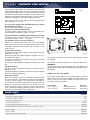
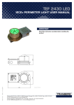
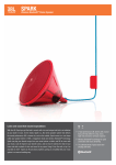
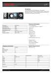
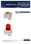
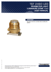
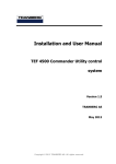
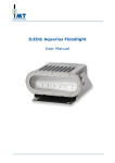
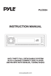
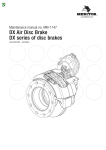
TEF 2430
IECEx Ex de LUMINAIRE USER MANUAL
IMPORTANT
Read this instruction carefully before installing the
product
TUM 2373
REV. E 14.10.2014
240A103162
Tranberg AS | P.O. Box 8033 | N-4068 Stavanger | Norway | Tel.: (47)51 57 89 00 | Fax.: (47)51 57 89 50
E-mail: [email protected] | www.tranberg.com
Tranberg Systems | Hjulmagervej 15C | 7100 Vejle | Denmark | Tel.: (45) 75 85 83 80
E-mail: [email protected] | www.tranbergsystems.com
TEF 2430
LUMINAIRE USER MANUAL
INTRODUCTION
APPROVAL
Thank you for purchasing this product!
For installation, maintenance and assurance of a long life of
this product, please follow this manual.
Ex Explosion category:
II 2 G Ex de IIB Gb T5
(ATEX/IECEx)
Ex de IIB T5 (Canada)
Class I, Zone 1, AEx de IIB T5 (US)
APPLICATIONS
Certificate No.:
IECEx NEM 13.0016X
Nemko 03ATEX064X
Signal lighting
Approved for use in:
Zone 1, Zone 2 and Safe Area
Obstacle marking
Marking:
Notified body:
0470
II 2 G Ex de IIB Gb T5
Ex de IIB T5
Class I, Zone 1, AEx de IIB T5
•
•
•
•
Deck lighting
Perimeter lights on helideck
CONTENT IN BOX
The product is fully assembled, and ready for installation.
216432
Nemko AS, Norway
CSA International, Canada
INSTALLATION INSTRUCTIONS
SAFETY PRECAUTIONS
Only qualified personnel are allowed to perform installation
and maintenance tasks to this equipment.
Note that changes made to the product and/or installation
of components which do not conform to the approval,
may be a safety violation. The manufacturer will in no
circumstance be held responsible for such activity.
For your health and safety, always use safety gear suited
for the task. Be certain to follow codes, regulations and/or
specific procedures that are related to the installation.
The equipment is ready for installation when leaving the
production facilities of Tranberg AS. Check the condition of
the equipment and the contents when unpacking. Any damage done to the equipment during the transportation is not
the responsibility of Tranberg AS. If the content is not complete, file a claim to the manufacturer immediately.
TOOLS REQUIRED
The TEF 2430 is mounted on a bracket which have several
mounting choices using 2 pcs. of M8 (max.) bolts and nuts,
or a 2” pipe. The dimensions of the mounting bracket are
shown in fig. 1.
Regular tools required for installation.
Important when mounting the luminaire:
• Tools for mounting, e.g. 13 mm wrench - to fasten the
luminaire
• 3 mm hexagon key (Unbrako) - for lock/unlock safety
pin on the guard-ring
• Flat head screwdrivers, approx. 3,5 mm for connecting to terminal block and 8,0 mm for junction box lid/
earth screw
• 32 mm wrench - to disassemble the blind plug, and
assemble the cable gland
• 25 mm wrench - for tightening the pressure nut on the
cable gland
MAINTENANCE INSTRUCTIONS
The luminaire should be inspected according to Company
routines. The manufacturer suggests regular check for
water intrusion/condensation which should be removed
immediately.
When cleaning, use only mild detergents. Alcohol or
petroleum based products may damage lens, paint or
plastic components. When cleaning the dome use moist
cloth to avoiding electrostatic hazard.
The luminaire must always be installed in such a way that
the junction box is fully supported from underneath. Normally the entire luminaire would be installed to a flat surface, which provides a proper support for the junction box.
In cases where the junction box cannot be mounted on the
same surface as the lamp housing/bracket, a full and rigid
support must be provided for the junction box. An unsupported junction box may be damaged if stepped upon.
Likewise an unsupported junction box that is forced down
by e.g. a pull of electrical cables, may expose the gasket
between the junction box and lamp housing.
Do not use excessive force when tightening the four screws
on the junction box lid, and never use a power screwdriver.
Excessive force may bend the lid and provide a way for water to enter the junction box. When closing the lid on the
junction box, please ensure that no electrical wires, or the
safety wire to the lid itself, are jammed between the lid and
the junction box.
Not following these instructions may lead to a risk of water
ingress into the luminaire. The manufacturer assumes not
responsibility when these guidelines are not followed.
The terminal block of this luminaire is of the “cage clamp”
type and one needs either special tool or just a small flat
head screwdriver to connect the cable to terminal block.
The cable glands are approved for a specific cable diameter.
TEF 2430
LUMINAIRE USER MANUAL
These data can be found in the certificate of the ATEX approved cable glands. Make sure this is not violated. Use of
cable with other dimensions is a safety violation and should
be avoided. Any damage caused by use of incorrect cable
gland not matching the cable dimension, is not the responsibility of Tranberg AS and is not covered by warranty.
Fig. 1
Max. cross section of the cable to be connected to the
terminal blocks, is 2,5 mm².
To connect the wiring of the TEF 2430 luminaire, perform
the following procedure:
Remove the cover from the junction box.
Connecting cable for 230/120 VAC:
The main power (230/120 VAC) is to be connected to the
terminal blocks marked 11 and 22, see fig. 2
Connecting cable for 24 VDC Compact fluorescent lamp:
The main power (24 VDC) is to be connected to the terminal blocks marked ++ and - -, see fig. 2
The 24 VDC version not to be grounded.
2
1
Make sure electrical connections are safe and reliable.
Make sure the wire slack is as needed. Reinstall the cover.
If properly mounted and installed, the luminaire is now
ready for use.
Replacement of lamp:
Deactivate the input power. Remove the unlock safety pin,
marked as 1 in fig. 3
Remove the ring with globe and guard, marked 2 in fig. 3,
and replace the lamp.
If necessary lubricate the threads with grease (Renolit
Unitemp 2, from Fuchs).
Reinstall the ring with globe and guard, and fasten the safety
pin.
Troubleshooting:
No light - Check main power, connections to the terminals
blocks or lamp.
If the light still does not function, contact the nearest Tranberg
dealer or Tranberg AS directly.
Safety precautions:
Note that changes made to this product and/or installation of components, which do not conform to the approval,
may be a safety violation. The manufacturer will under no
circumstances be held responsible for personal injuries,
death or any damage caused by such activity. For your
health and safety, always use safety gear suited for the
task, and follow company guidelines and all relevant rules
and norms for installation, where applicable.
Fig. 2
Fig. 3
Do not open any part of the luminaire without disconnecting
line voltage.
The luminaire is to be used in Zone 1, Zone 2 or Safe Area.
WARNING!
The luminaire can only be installed in Zone 1 and Zone 2 if
equipped with ATEX and IECEx approved cable glands and
blind plugs.
Rubber seal and cable glands:
Be sure to install the cable in a way whhich prevents water to
penetrate into the enclosure through the cable gland. Also
make sure to use the correct rubber seal when you install
the cables into the luminaires.
Cable diam.
12,0 - 15,0mm
15,0 - 20,1mm
Size
Ø26,8/15,0x10mm
Ø26,8/20,3x10mm
Part No.
5002 0140
5002 0139
SPARE PARTS
Description
Part No.
Lamp insert, complete 230 VAC
1671
Lamp insert, complete 120 VAC
3059
Lamp insert, complete 24V DC
3191
Fluorescent tube 7W, G23
9400 032
Fluorescent tube, PLC-10W/827-4 pins, 24V
9400 071
Cable gland Exe M25 (Includes two rubber seals for cables 12 - 20m)
6222 502
Reactor, 230VAC
5086 0035
Reactor, 120VAC
5086 0031
Electronic reactor for 24 VDC revision
5028 0049
TEF 2430
LUMINAIRE USER MANUAL
Terminal block, Wago
5028 0008
Terminal block with brass plate
4128
Lamp holder, for PL-C 13W 120VAC
5088 0030
Lamp holder, G23 for PL-S 7W 230VAC
5088 0031
Lamp holder, G24q for PL-C 13W 24VDC
5088 0034
Globe with guard, yellow/amber
2036
Globe with guard, clear
1223
Globe with guard, green
1224
Globe with guard, red
1225
Globe with guard, yellow
1226
Globe with guard, blue
1227
Gasket (o-ring) for globe (107,5 - 3,53), nitrile
5000 8009
TECHNICAL DATA
Material:
Cast copper alloy. Globe polycarbonate Lexan, Junction box in AISI 316L
Supply (Input) voltage:
24 VDC, 120VAC 60Hz, 230VAC 50/60Hz
T-rating:
T5
IP-protection:
IP66/67
Power consumption:
Max 20 Watt
Light source:
PL-S 2x7W (230 VAC)
PL-C 13W (120 VAC)
PL-C 10W (24 VDC)
15W Compact fluorescent (integrated), only for ATEX approval, not for CSA approval
Tamb:
-30°C to +45°C (Arctic version: -55°C to +45°C)
Weight:
6 kg.
Compliance with:
CENELEC EN 60079-0:2013
CENELEC EN 60079-1:2007
CENELEC EN 60079-7:2007
CSA Standard C22.2 No 0-M 91: General requirements - Canadian Electrical Code, Part II
CSA Standard C22.2 No 0.4M 1982: Bonding and Grounding of Electrical Equipment
(Protective Grounding)
CAN/CSA Standard C22.2 No 43-M 1984: Lampholder
CAN/CSA Standard C22.2 No 250.0-00: Luminaires
CAN/CSA E60079-0:02: Electrical Apparatus for explosive gas atmospheres - Part 0:
General Requirements
CAN/CAS E60079-1:02: Electrical Apparatus for explosive gas atmospheres - Part 1:
Flameproof Enclosures “d”
CAN/CAS E60079-7:02: Electrical Apparatus for explosive gas atmospheres - Part 7:
Increased safety “e”
UL 1598-2000, First Edition, UL Standard for Safety, Luminaires
UL 542-1999, Eight Edition, UL Standard for Safety, For Lampholders, Starters and
Starter Holders for Fluorescent Lamps
UL 935-2001, Tenth Edition, UL Standard for Safety, For Fluorescent-Lamp Ballasts
ANSI/UL 60079-0-2002, First Edition, Electrical Apparatus for Explosive Gas
Atmospheres, Part 0: General Requirements.
ANSI/UL 60079-1-2002, First Edition, Electrical Apparatus for Explosive Gas
Atmospheres,
Part 1:Flameproof Enclosures “d”
ANSI/UL 60079-7-2002, First Edition, Electrical Apparatus for Explosive Gas
Atmospheres,
Part 7:Flameproof Enclosures “e”
Tranberg AS | P.O. Box 8033 | N-4068 Stavanger | Norway | Tel.: (47)51 57 89 00 | Fax.: (47)51 57 89 50
E-mail: [email protected] | www.tranberg.com
Tranberg Systems | Hjulmagervej 15C | 7100 Vejle | Denmark | Tel.: (45) 75 85 83 80
E-mail: [email protected] | www.tranbergsystems.com