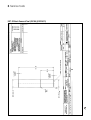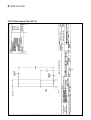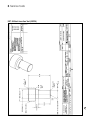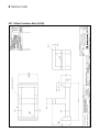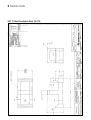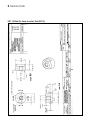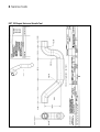
1
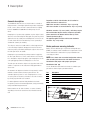
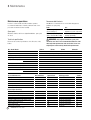
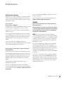
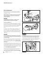
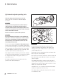
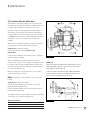
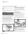
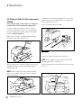
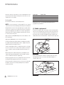
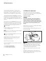
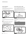
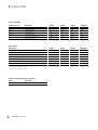
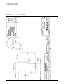
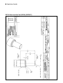
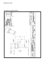
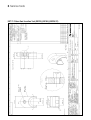
an ArvinMeritor brand
Maintenance manual no. MM-1147
DX Air Disc Brake
DX series of disc brakes
Issued 06/2003 - 2nd Edition
Service Notes
Before You Begin
This publication provides installation and maintenance procedures
for the DX Air Disc Brake.
The information contained in this publication was current at the
time of printing and is subject to revision without notice or liability.
You must understand all procedures and instructions before you
begin maintenance and service procedures.
Access Information on ArvinMeritor's Web
Site
Additional maintenance and service information for ArvinMeritor's
commercial vehicle systems component lineup is also available at
www.arvinmeritor.com.
To access information, click on Products & Services/Tech Library
Icon/HVS Publications. The screen will display an index of
publications by type.
You must follow your company's maintenance and
service guidelines.
You must use special tools, when required, to avoid serious
personal injury and damage to components.
Meritor uses the following notations to alert the user of possible
safety issues and to provide information that will help to prevent
damage to equipment and components.
WARNING
A WARNING indicates a procedure that you must follow
exactly to avoid serious personal injury.
CAUTION
A CAUTION indicates a procedure that you must follow
exactly to avoid damaging equipment or components.
Serious personal injury can also occur.
NOTE: A note indicates an operational, procedure or instruction
that is important for proper service. A NOTE can also supply
information that will help to make service quicker and easier.
This symbol indicates that you must tighten fasteners to a
specific torque.
Information contained in this publication was in effect at the time the publication
was approved for printing and is subject to change without notice or liability.
ArvinMeritor Commercial Vehicle Systems reserves the right to revise the
information presented to discontinue the production of parts described at any time.
2
ArvinMeritor DX Air Disc Brake
Contents
pg. 05
06
06
Section 1: Description
General description
Brake pad wear indicator
07
Section 2: Introduction
08
10
12
13
14
15
Exploded view - Pre March 2001 production
Exploded view - Post March 2001 production
Operating principles
Automatic self-adjuster mechanism
Automatic clearance compensation
Thrust plate
17
Section 3: Maintenance
18
19
20
21
21
24
25
25
26
28
31
32
34
36
38
38
39
Maintenance operations
Maintenance intervals
A - Pad Replacement
B - Manual Adjustment
C - Rotor Inspection
D - Automatic Adjuster Operating Tests
E - Checking Slide Pin Bush Wear
F - Brake Slide Pin Checks on vehicle
Brake Servicing on bench
G - Disassembly of Actuating System
H - Slide Pin & Bushing Replacement
I - Actuating Piston Seal Boot Replacement
J - Saddle Replacement
K - Eccentric Shaft & Cover Plate Replacement
L - Stabiliser Bar Replacement
M -Lever Replacement
N - Thrust Plate Centering in Saddle
O - Re-assembly of brake unit on vehicle and pad refitting
41
Section 4: Torque chart
42
Torque Chart, Special tools, Sealants
43
Section 5: Troubleshooting
44
Troubleshooting
47
Section 6: Service tools
ArvinMeritor DX Air Disc Brake
3
Terms used in this manual
Manufacturer:
ARVINMERITOR CVS
Manual:
Maintenance manual no. MM-1147
Device:
Air disc brake, DX series
Technician:
Qualified personnel working on brake maintenance and servicing.
4
Warranty
Warranty applies to the air disc brake installed on vehicles for
which it was designed. Warranty is void in the following cases:
• Improper use of the vehicle on which the air disc brake is
installed (usage conditions, overloading etc.)
• Tampering with vehicle components that may affect brake
performance.
• Use of non-original spare parts.
Maintenance and servicing:
Maintenance and servicing refer to periodical checks and/or
replacement of device parts or components. It also refers to the
determining of the cause of a malfunction in order to restore the
initial operating conditions.
• Improper installation, adjustment, repair or modification.
Operator:
Any person who will use the device as part of a more complex
device.
Further information on warranty conditions may be obtained
directly from the manufacturer or by referring to the ArvinMeritor
web site www.arvinmeritor.com
ArvinMeritor DX Air Disc Brake
• Poor or improper maintenance (including consumables other
than those specified).
Description
1
pg. 06
06
General description
Brake pad wear warning indicator (PWWI)
ArvinMeritor DX Air Disc Brake
5
1 Description
General description
The ArvinMeritor CVS DX series of air disc brakes is a family of
high performance, low weight, high efficiency brakes designed for
trucks, coaches, buses and other commercial vehicles requiring
between 10,000 and 23,000 Nm of braking torque at each
wheel.
Clamping force is produced by a globular cast iron caliper located
above the rotor and housing two lining pads. The pads are pushed
against the rotor by a dual piston actuating block connected to an
eccentric shaft, which is in turn driven by a lever operated by a
standard air actuator (air chamber).
The caliper is carried on a saddle which is a fixed support bolted
to the axle flange. Equalised clamping action both on the inner
and outer pads is generated by allowing the caliper to float on the
two slide pins fixed to the saddle.
Clamping force generated by the primary actuation is applied to
the inner pad, which forces it into contact with the rotor. Reactive
force through the caliper body applies equal clamping force to the
outer pad applying a balanced clamping force to the rotor.
The slide pins also allow the caliper to freely position itself on the
saddle to compensate for the reduction in lining pad thickness
due to wear.
An automatic self-adjuster mechanism is incorporated in order to
maintain constant clearance between pads and rotor. The
automatic adjuster operates on each clamping action to sense
excessive pad-rotor clearance, and reduces excessive clearance
by a fixed proportion with each actuation.
For brake adjustment and new lining installation, the brake
incorporates provision for manual adjustment, easily performed by
using a standard hexagonal wrench.
Brake actuation can be either clockwise or counter clockwise,
depending on how the air actuator has been installed on brake
unit.
6
ArvinMeritor DX Air Disc Brake
Regardless of which side the brake unit is installed on
vehicle, the brake is referred to as:
RIGHT when actuation is clockwise - Fig. 2-2 a) and b)
LEFT when actuation is counter clockwise - Fig. 2-2 c) and d)
Clockwise actuation - Fig. 2-2 a) and b) - will always require
left-hand threaded adjuster sleeves and pistons (actuation
pistons marked on the bottom with the letter L) and its
related right housing (R.H.).
The opposite applies for brakes with counter clockwise
actuation - Fig. 2-2 c) and d).
Brake pad wear warning indicator
Brakes can have different types of pad wear warning indicators
(PWWI) according to vehicle manufacturer’s requirements. Follow
vehicle manufacturer’s instructions for proper installation and
connecting procedures.
NOTE: Parts shown refer to standard configuration and may
differ according to brake version and model. Use data on
identification label (40) to order proper spare parts.
Identification label (40)
See the identification label attached on brake for suitable spare
part and note down all spare part data indicated.
Ref.
1
2
3
4
5
Description
Brake Identification Number (ArvinMeritor )
Manufacturing Date
Brake Identification Number (Customer)
Brake Serial Number
ArvinMeritor Logo
Introduction
2
pg. 08
09
10
11
12
13
14
15
Exploded view - Pre March 2001 production
Parts list
Exploded view - Post March 2001 production
Parts list
Operating principles
Automatic self-adjuster mechanism
Automatic clearance compensation
Thrust plate
ArvinMeritor DX Air Disc Brake
7
Exploded view
Pre March 2001 production
8
ArvinMeritor DX Air Disc Brake
Parts list
Pre March 2001 production
Ref
1
2
3
4
5
6
7
8
9
10
11
12
13
14
15
16
17
18
19
20
21
22
23
Description
Stabiliser bar retaining pin
Pin clip
Caliper
Anti-rattle spring
Stabiliser bar
Cover plate gasket
Eccentric shaft
Cover plate
Cover plate screws
Eccentric shaft seal
Eccentric shaft seal boot
Clamp bolt (lever)
Lever
Clamp bolt nut (lever)
Eccentric shaft bearing unit
End plate gasket
Slide pin bushing
Eccentric shaft support bearing
Actuation block
Damping spring
Snap ring
Bevel gear / torque limiter
Adjustment box **
(preinstalled unidirectional bearing)
Q.ty
1
1
1
2
1
1
1
1
2
1
1
1
1
1
2
1
2
1
1
2
2
1
1
Ref
24
25
26
27
28
29
30
31
32
33
34
35
36
37
38
39
40
41
42
43
44
45
46
47
48
Description
Damping ring
Compression spring
Air actuator end plate and bracket
Flathead screw (end plate screw)
End plate cap
Plug (of adjuster port)
Copper washer
Hexagonal head screw (end plate screw)
Adjuster device screw
Adjuster gear segment
Adjuster sleeve gear *
Slide pin protective cap
Adjuster sleeve **
Slide pin locking screw
Actuating piston **
Slide pin
Identification label
Slide pin seal boot
Actuating piston seal boot
Roll pin
Thrust plate
Saddle
Actuating piston screw
Brake pads
Brake pad wear indicator (if fitted)
Q.ty
2
1
1
2
1
1
1
4
1
1
2
2
2
2
2
2
1
2
2
2
1
1
2
2
1
* Gear is shown separately since it is an integral part with
adjuster screw.
** These components are different according to actuation
direction (clockwise or counter – clockwise) (Fig. 2-2).
ArvinMeritor DX Air Disc Brake
9
Exploded view
Post March 2001 production
10
ArvinMeritor DX Air Disc Brake
Parts list
Post March 2001 production
Ref
1
2
3
4
5
6
7
8
9
12
13
15
17
18
19
20
21
22
23
24
25
26
27
Description
Stabiliser bar retaining pin
Pin clip
Caliper
Anti-rattle spring
Stabiliser bar
Cover plate gasket
Eccentric shaft
Cover plate housing
Cover plate screws
Clamp bolt (lever)
Lever
Eccentric shaft bearing unit
Slide pin bushing
Eccentric shaft support bearing
Actuation block
Damping spring
Snap ring
Bevel gear / torque limiter
Adjustment box **
(preinstalled unidirectional bearing)
Damping ring
Compression spring
Air actuator end plate and bracket
(shape may vary due to brake part number)
End plate screws
(style may vary due to brake part number)
Q.ty
1
1
1
2
1
1
1
1
2
1
1
2
2
1
1
2
2
1
1
2
1
1
Ref
28
29
30
32
33
34
35
36
37
38
39a
39b
40
41
42
43
44
45
46
47
48
49
50
51
Description
End plate cap
Plug (of adjuster port)
Copper washer
Adjuster device screw
Adjuster gear segment
Adjuster sleeve gear *
Slide pin protective cap
Adjuster sleeve **
Slide pin locking screw (long)
Actuating piston **
Slide pin (to suit long locking screw)
Slide pin (to suit short locking screw)
Identification label
Slide pin seal boot
Actuating piston seal boot
Roll pin
Thrust plate
Saddle
Actuating piston screw
Brake pads
Brake pad wear indicator (if fitted)
Cover plate eccentric shaft seal
Eccentric shaft seal
Slide pin locking screw (short)
Q.ty
1
1
1
1
1
2
2
2
1
2
1
1
1
2
2
2
1
1
2
2
1
1
1
1
6
* Gear is shown separately since it is an integral part with
adjuster screw.
** These components are different according to actuation
direction (clockwise or counter – clockwise) (Fig. 2-2).
ArvinMeritor DX Air Disc Brake
11
2 Introduction
Installation configuration
A
B
C
D
Fig. 2.2
Operating principles
Actuation
Linear force from the air actuator (air chamber) is converted by
lever action to rotary torque on the main eccentric shaft.
Rotation of the shaft, supported by two roller bearings, causes the
block to move towards the inside of the caliper. The ratio between
the air actuator force and force on rotor is between 12,5 and
16,2 depending on brake model. All radial loads in the eccentric
shaft are absorbed by two supporting roller bearings maintaining
an efficiency of around 95% because of total absence of sliding
friction in the system.
12
ArvinMeritor DX Air Disc Brake
Clamping
The caliper assembly is free to float on the slide pins attached to
the saddle. This exerts clamping force on the inner pad and
determines a reaction through the caliper body, ensuring that both
pads are loaded onto the rotor by an equal force.
2 Introduction
Automatic self-adjuster mechanism
Fig. 2.3
Automatic self-adjuster mechanism
Ref
1
2
3
4
5
6
7
Description
Actuating piston
Adjuster sleeve gear
Eccentric shaft
Actuation block
Bevel gear
Box (adjuster gear train)
Adjuster gear segment
ArvinMeritor DX Air Disc Brake
13
2 Introduction
Automatic self adjuster mechanism
(clearance compensation)
This mechanism, located inside the caliper, allows control of
clearance caused by continuous wear of the brake pads. The
action is automatic and occurs during normal brake application.
Clearance compensation is performed as indicated in the
following four steps.
Step 1 (actuation of eccentric shaft)
a) Actuating lever moves and eccentric shaft rotates.
b) Block lifts and begins to move forward, carrying the adjuster
sleeves and pistons with it (Fig. 2-4).
Step 1
Fig. 2.4
c) Eccentric shaft A begins turning within the gear plate segment,
eliminating clearance “h” between the adjuster gear section
slot B and the shaft integral tab sides (Fig. 2-5).
Step 2
C
Step 2 (clearance compensation device)
d) Adjuster gear segment begins to turn causing the rotation of
bevel gear adjuster C (Fig. 2-5).
B
e) Bevel gear rotation causes the adjuster shaft to rotate by
means of the ball torque limiter and the rotation is transmitted
to the box central gear through the unidirectional bearing.
f) Central gear rotation, through the box gear train, causes the 2
adjuster sleeves to rotate.
h
A
Fig. 2.5
At this stage, depending on the amount of wear of the brake
pads, one of the following two conditions will occur:
Condition A:
No adjustment is required as clearance between pads and rotor is
correct.
Condition B:
Adjustment is required as clearance between pads and rotor is
excessive.
Step 3 (Condition A)
g) At this point, when the adjusters begin to turn, the pads
contact the rotor before the sleeves begin to turn and clamping
force F (braking) begins to build up.
Step 3A
Fig. 2.6
h) Clamping force generates friction in the screw threads between
the adjuster sleeves B and pistons A, and friction under the
flanged head of the adjuster sleeves (Fig. 2-6).
14
ArvinMeritor DX Air Disc Brake
2 Introduction
i) The friction build-up prevents rotation of the adjuster sleeves
whilst the torque limiter allows the adjuster shaft to rotate with
respect to the bevel gear. The adjuster drive train is locked by
the friction in the system and no adjustment takes place. The
main gear turns but does not transmit motion due to the
torque limiter blocking.
Step 3 (Condition B)
j) During the first stroke stage, before the pads come into
contact with the rotor, the adjuster sleeves are turned by the
gear box.
k) Sleeve rotation, due to the threaded coupling with pistons,
causes pistons to be unscrewed. This determines the length ‘L’
of the extracted part of the pistons to increase and the pads
approaching stroke towards the rotor to reduce (Fig. 2-7).
Step 3B
Fig. 2.7
i) When the pads come into contact with the rotor the conditions
mentioned above in step 3 A (g-i) are repeated, thus halting
the movement.
Step 4 (Brakes released)
l) When the brake pedal is released, pressure is discharged from
the air actuator and the brake actuating lever returns to its
rest position pulled by the returning action of the internal air
actuator spring. The eccentric shaft and the adjuster gear
segment rotate in reverse direction together with the bevel
gear.
Step 4
Fig. 2.8
m) The unidirectional bearing free-wheels without transmitting
motion to the gear housing, thus avoiding brake adjustment.
The relative piston / sleeve adjustment position does not vary.
Therefore, clearance compensation of pre-existing rotor and
pads remains unchanged. (Fig. 2-8).
Damping
Compression springs are mounted in front of and behind the
gearbox in order to dampen vibration caused by vehicle movement.
This prevents induced vibrations from occurring, which could
modify the clearance setting between rotor and pads (Fig. 2-9).
A
A
A
Thrust plate
An important feature of the DX family of brakes is the setting of
the thrust plate within the saddle abutments. Although this is
factory set and provided the 2 locking screws are not removed
from the thrust plate, no resetting should be necessary.
Damping
Fig. 2.9
However should the screws become disturbed a procedure for
resetting should be followed: see maintenance Section N “Thrust
Plate Centering in Saddle”.
ArvinMeritor DX Air Disc Brake
15
16
ArvinMeritor DX Air Disc Brake
Maintenance
3
pg. 18
19
20
21
21
24
25
25
26
28
31
32
34
36
38
38
39
Maintenance operations
Maintenance intervals
A - Pad Replacement
B - Manual Adjustment
C - Rotor Inspection
D - Automatic Adjuster Operating Tests
E - Checking Slide Pin Bush Wear
F - Brake Slide Pin Checks on vehicle
Brake Servicing on bench
G - Disassembly of Actuating System
H - Slide Pin & Bushing Replacement
I - Actuating Piston Seal Boot Replacement
J - Saddle Replacement
K - Eccentric Shaft & Cover Plate Replacement
L - Stabiliser Bar Replacement
M - Lever Replacement
N - Thrust Plate Centering in Saddle
O - Re-assembly of brake unit on vehicle and
pad refitting
ArvinMeritor DX Air Disc Brake
17
3 Maintenance
Maintenance operations
Recommended lubricants
In order to ensure reliable and efficient brake operation,
recommended maintenance intervals, lubricants and correct
procedures should be followed carefully.
ArvinMeritor recommends the use of two lubricating greases
(available as spare parts).
Spare parts
Warranties shall be null if non-original ArvinMeritor spare parts
are used.
Technical specifications
new :
min. :
General Maintenance
Pad replacement
Manual clearance adjustment
Rotor overhaul
Operating tests
Checking slide pin bush wear
Brake Caliper Servicing:
Disassembly of Actuating System
Slide Pin & Bushing Replacement
Actuating Pin Seal Boot Replacement
Saddle Replacement
Eccentric Shaft & Cover Plate Replacement
Stabiliser Bar Replacement
Lever replacement
Thrust Plate Centering
ArvinMeritor DX Air Disc Brake
should be used. Use of non-recommended lubricants shall
adversely affect performance and service life. Use of nonoriginal parts could seriously affect brake performance.
DX175
DX195
DX225
Disc brakes
Disc brakes
Disc brakes
Floating, with pad lining compensation device
2
2
2
28
38
48
19
20
23
2
2
2
Self ventilated
336
378
436
178
218
234
34
45
45
28
39
39
Rotor type
Rotor outside diameter (mm)
Rotor inside diameter (mm)
Rotor thickness (mm)
new :
min. :
18
Use
Use on all actuation and
adjustment system components
Use only for slide pin plain
bearings (bushings)
WARNING: Only original ArvinMeritor spare parts
Below are the technical specifications of the DX series of disc
brakes.
Disc Brake Model
Type
Caliper
No. of pistons per caliper
Weight (kg)
Lining thickness (mm)
Code
MBG 1003 (grease)
(Fuchs Unitemp 2)
MBG 1004 (lubricating oil)
(Kluber Constant GLY 2100)
DX225/21
Disc brakes
2
41
22
2
420
251
45
39
No. Technicians
1
1
1
2
1
Special Tools
NO
NO
YES
NO
NO
Working position
On vehicle
On vehicle / On bench
On vehicle / On bench
On vehicle
On vehicle
Section
A
B
C
D
E
1
1
1
1
NO
YES
NO
NO
1
1
1
NO
NO
YES
On vehicle / On bench
On bench
On bench
On bench
On bench / On vehicle
On bench / On vehicle
On bench / On vehicle
On bench
G
H
I
J
K
L
M
N
3 Maintenance
Maintenance Intervals
Although there is no routine maintenance of the brake assembly
required, it is important the following inspections are carried out
at the periods specified, or those detailed in the vehicle or trailer
manufacturer’s manual.
Service intervals
Every 3 months or 20000 km.
A visual inspection of pad life should be made. Brake pads should
be replaced when the lining thickness has worn to 2.0 mm.
Visually inspect the general condition of the brake assembly for
damage or corrosion.
Inspect the slide pin and actuating piston seal boots and ensure
they are undamaged and securely located. If any of the boots are
detached or damaged the relevant part of the brake should be
dismantled and the components examined for corrosion and
damage.
If there is any doubt in the suitability for further service,
replace/rectify in accordance with the instructions of this manual
or the vehicle/trailer manufacturer’s instructions.
Every 12 months or at the vehicle / trailer manufacturer’s
recommendations.
Remove brake pads as described in the pad replacement section.
Inspect the slide pin and actuating piston seal boots and ensure
they are undamaged and securely located. If any of the boots are
detached or damaged the relevant part of the brake should be
dismantled and the components examined for corrosion and
damage.
Replace/rectify in accordance with the vehicle /trailer
manufacturer’s instructions.
If there is any doubt in the suitability for further service, replace
with new components.
Check the slide pin bush for wear in line with instructions in
Section E “Checking Slide Pin Bush Wear”.
WARNING
Take care not to trap fingers whilst checking the sliding
action of the brake.
Check the brake disc for signs of heavy grooving; cracking
or corrosion and the thickness dimension are in accordance
with recommendation of the manual of the vehicle/trailer
manufacturer’s recommendations.
NOTE: These service intervals are meant as a guide, the
frequency should be tailored to suit the environmental conditions
of the brake assembly and hence to the vehicle/trailer operating
conditions, so therefore it is up to the operator to determine the
most appropriate service intervals with technical support from
ArvinMeritor if necessary.
These service intervals are the maximum recommended times
under normal operating conditions. Extreme temperatures or
adverse conditions (e.g. dusty or severe environments, frequent
uphill driving, very low temperatures) will require more frequent
servicing. It is the responsibility of the vehicle operator to
schedule these intervals, with technical support from ArvinMeritor
if necessary.
In some cases, it is possible to carry out operations with brake
unit mounted on vehicle. However, ARVINMERITOR recommends
that all operations (with the exception of pad replacement and
operating tests) be carried out with the brake unit removed from
vehicle and installed on bench. This promotes safer working
conditions and better results.
Check the housing assembly slides easily on the slide pins
secured to the saddle. If the housing does not slide easily, remove
from the saddle as described in Section J “Slide Pin & Bushing
Replacement”.
ArvinMeritor DX Air Disc Brake
19
3 Maintenance
(A) Pad replacement
Brake pad replacement is necessary when the friction lining is
worn down to a thickness of 2 mm (total thickness inclusive of
support plate, is 9 mm).
With the vehicle on a hard level surface, fit anti-roll chocks
under the road wheels to prevent it from moving either
forward or backwards.
WARNING
Carefully follow the manufacturer's instructions when
jacking the vehicle and removing the road wheel.
Fig. 3.1
Preliminary procedures:
If necessary, disarm the parking spring following the air actuator
manufacturer's instructions. Remove dirt and debris from caliper.
Remove the pin clip A and the pin B allowing the stabiliser bar C
to rotate and be hinged to the caliper on the lever's side.
(Fig. 3.1)
Depending on vehicle operating conditions, pad lining wear can
often be uneven (about 1 mm in tangential and radial wear).
The use of a vacuum cleaner is highly recommended to eliminate
build up of dust. Otherwise, remove dust with water-dampened
shop towels.
Fig. 3.2
WARNING:
Do not use compressed air to clean brakes or rotor. Linings
are non-asbestos but lining dust is an irritant if inhaled and
is harmful to health.
(Fig. 3.2) Pull out the inner brake pad. If pad removal is difficult
due to rotor wear (a ridge build-up on the outer diameter of the
rotor) then manually de-adjust the brake (in Section B “Manual
Adjustment”).
WARNING :
This operation requires the caliper to be moved on its slide
pins. Extreme care must be taken to avoid trapping fingers.
(Fig. 3.3) Clean the 8 pad support plates in the saddle with a wire
brush removing any build-up of debris or rust. This allows the
new pads to be correctly seated in position.
Pull the caliper axially outwards (towards the road wheel) to free
the outboard pad A and pull it out. Discard the worn pads and the
anti rattle springs. Visually inspect the rotor for signs of excessive
corrosion, physical damage, scoring on braking surfaces or signs
of cracking (in Section C “Rotor Inspection”).
Using an emery cloth, remove light surface rust from the rim of
the rotor. If unsure of rotor integrity, replace it with a new one.
Light surface crazing of the rotor is normal and acceptable.
Fig. 3.3
20
ArvinMeritor DX Air Disc Brake
3 Maintenance
Inspect the stabiliser bar for signs of damage, distortion, wear or
corrosion. If in doubt of bar integrity, replace it.
(Fig. 3.4) Completely de-adjust the automatic clearance
compensation device (in Section B “Manual Adjustment”).
Install new pads and new anti-rattle springs. Check that pads are
correctly fitted with friction material in contact with rotor. Hinge
down the stabiliser bar onto the springs anti-rattle and retain in
position with pin and new pin clip. Manually adjust the brakes (in
Section B “Manual Adjustment”).
a) During inspection of pad to rotor clearance.
b) During fitting of new pads.
To manually adjust the brake first remove the manual adjustment
port plug and then rotate the mechanism using a 6 mm
Hexagonal wrench. The gear train will ensure that the adjuster
sleeves will be turned equally.
The operation which allows pistons to be extended, thus reducing
pad to rotor clearance is called adjustment. The opposite
operation is called de-adjustment.
De-adjustment direction depends on eccentric rotation direction.
Wrench should be turned counter clockwise on brakes with
clockwise lever actuation (de-adjustment rotation direction is
indicated with an arrow on end plate near the manual adjuster
plug hole). (Fig. 3.5)
In general, de-adjustment or back adjustment is achieved when
the wrench is turned in the direction which produces clicking feel.
(This indicates that the torque limiter is slipping).
Fig. 3.4
If necessary, release the parking brake spring on the air
actuators. Verify correct operation by actuating brakes about ten
times.
The actual position of brake unit on vehicle can vary from
one model to another.
Turning the wrench in the opposite direction will result in a much
smoother and quieter action, which will give positive adjustment
and reduce pad to rotor clearance.
During brake de-adjustment, stop turning the wrench if resistance
is felt. This indicates that the adjuster pistons are fully retracted.
Further turning of the wrench could lock the adjuster pistons in
WARNING
Use only approved brake pads complying with original
specifications. Use of non-approved brake pads could
adversely affect brake performance and pad life, as well as
rotor life and efficiency.
(B) Manual adjustment
It is possible to manually adjust pad to rotor clearance.
Under the following conditions it will be necessary to manually
adjust brake:
Fig. 3.5
ArvinMeritor DX Air Disc Brake
21
3 Maintenance
the sleeves, thus preventing auto-adjustment operation or cause
damage to the adjuster mechanism.
CAUTION:
Do not use automatic unscrewing devices during manual
adjustment. If used by mistake, breakage of adjuster box
gears could occur. Do not exceed adjustment torque of 6 Nm.
Rotate the adjustment mechanism in the direction in which
clicking is not heard or felt. Continue rotation until both pads
come into contact with rotor. Then in the opposite direction, turn
the hexagonal until 7 torque limiter notches are heard or felt, this
will set the initial pad to disc clearance.
(C) Rotor inspection
Rotors should be inspected whenever the brakes are serviced or
new pads are fitted, or immediately if erratic braking performance
is perceived. The rotor condition should be visually inspected.
Check braking surface conditions in order to determine if the rotor
needs to be replaced.
Accurate cleaning of the rotor is necessary at 100000 km (or 12
months) intervals. Remove all rust or debris caused by wear from
rotor rim, from support points of the pads in the saddle and from
all caliper actuation surfaces.
See below a list of conditions often detected on rotors:
Remove the hexagonal wrench, replace the port plug and
washer and tighten to 14 Nm.
Condition
Surface crazing
Tolerance
Operation
None
Radial cracks
Description
Light short random crazing of braking
surfaces (Fig. 3.6 A)
Small slight cracks (Fig. 3.6 B)
Max. width 0.5 mm
Max. depth 1.0 mm
Radial extension of braking
surface less than 75%.
None if tolerance levels are not
exceeded.
If one of the tolerance levels is
exceeded, replace rotor.
Tangential scoring
Light circular grooves (Fig. 3.6 C)
Max. groove depth 0.5 mm
Heat spotted rotor
This condition indicates that the rotor has
been subjected to extremely high
temperatures that have caused a
structural change in the rotor material
and have caused the rotor to be more
susceptible to cracking. Residual internal
tension could lead to permanent rotor
distortion (Fig. 3.6 D).
Max. axial run-out 0.3 mm
Max. radial run-out 0.8 mm
Max. rotor thickness
variation 0.05 mm
None if tolerance levels are not
exceeded. Machine if tolerance
levels are exceeded (*)
(see Rotor resurfacing)
None if tolerance levels are not
exceeded.
Machine if tolerance levels are
exceeded (**)
(see Rotor resurfacing)
(*) Wear and grooves must be approx. the same on both surfaces. If wear is considerably different, brakes will not operate properly and
need to be inspected.
(**) If resurfacing does not remove the spots then the rotor must be replaced.
Excessive run out may be due to incorrect rotor assembly on the hub, excessive tightening torques or incorrectly adjusted wheel bearings.
Ensure that these conditions are avoided when reassembling. Use a dial test indicator (DTI) to check both axial and radial run-out as
illustrated in Fig. 3.6.
22
ArvinMeritor DX Air Disc Brake
3 Maintenance
A
B
max. length = 75% A
A
C
D
Fig. 3.6
Rotor resurfacing
Remove rotor as described in vehicle's service manual. Position
rotor on grinder. Eliminate all traces of defects found on rotor.
Resurfacing must be done on both sides of rotor.
Wear Limits
Wear limits for rotor are visually indicated by the bevel corner 3 x
30° on each outer diameter of both braking surfaces. A maximum
limit of 3 mm per each side is allowed for machining.
Minimal total thickness allowed for the worn rotor is indicated on
rotor outer edge (minimum thickness XY mm).
During resurfacing move the grinding wheel gradually until all
grinding swarf is removed.
Surface finish after machining should be max. 5 microns.
In order to guarantee total braking efficiency and safety, it is
recommended, when replacing one rotor, to replace the other
rotor on the same axle.
Minimal total thickness allowed for the worn rotor is:
- 39 mm for DX225, DX225/21 and DX195
- 28 mm for DX175
new
min.
thickness
Rotors may be resurfaced up to the minimal thickness allowed
(41 mm for DX225, DX225/21 and DX195; 30 mm for DX175
after resurfacing).
min.
ArvinMeritor DX Air Disc Brake
23
3 Maintenance
(D) Automatic adjuster operating tests
Pad wear compensation device check (on vehicle)
This procedure will check function of Automatic adjuster
mechanism.
WARNING
The operation must be performed on vehicle. Follow all
safety precautions and abide by standing regulations
concerning vehicle hoisting and workshop conditions. The
vehicle must be hoisted and the relative wheel of the device
to be tested should be removed.
Fig. 3.7
Clean the area where the operation will be performed.
WARNING
Do not use compressed air. Linings are non-asbestos but
lining dust is an irritant if inhaled and is harmful to health.
The use of a vacuum cleaner is highly recommended to
eliminate build up of dust. Otherwise, remove dust with
water-dampened shop towels.
Reset the manual adjuster (in Section B “Manual Adjustment”)
in order to have a total clearance of 2 mm between pad and rotor
(for rotors without wear ridge). The clearance should be measured
with a feeler gauge once the internal pad touches the rotor (pull
the gauge outwards). Should the rotor have a wear ridge, 2 mm
clearance could be achieved as follows: (Fig. 3.7)
Rotate adjustment device towards the position in which clicking is
no longer heard so that both pads are in contact with rotor. Rotate
the hexagonal wrench 360° in the opposite direction, i.e. 12
torque limiter notches.
By leaving a hexagonal wrench in the adjuster port, device
operation can be observed during test.
Fig. 3.8
If a wrench has been left in the device, at the end of this
operation it should have rotated between 180° & 270° from
starting point in normal conditions. If this is so, the next step
could be skipped. (Fig. 3.8)
For this purpose, be sure that the wrench does not interfere with
brake components all around (360°).
If the rotation is less than the stated value, actuate the brakes 50
times via the brake actuator. Measure the pad to rotor clearance
using feeler gauge.
The automatic adjuster device operates correctly if measured
clearance (with a feeler gauge) is between 0.6 and 1.0 mm, or if
Hexagonal wrench rotation needed to make the pad be in contact
with the rotor is between 90° and 180°.
Should this be the case, it should be remembered that the brake
should be de-adjusted as in the above step.
The complete brake assembly must be replaced if the clearance
is not within these limits.
24
ArvinMeritor DX Air Disc Brake
3 Maintenance
(E) checking slide pin bush wear
A
B
The following is a check that enables the wear on the slide pin
mechanism to be checked with the brake assembly in position on
the vehicle and to determine if replacement is necessary.
Z
Periodical checks of the slide pin bush wear should take place.
The frequency of the periodical checks must be determined by
the vehicle/trailer user. However a frequency of every 12 months
or 100000 kilometres must be considered although the frequency
will depend on the type of operation or the environmental
conditions.
2
90
With the aid of a DTI (Dial Test Indicator), movement of the brake
housing relative to the fixing saddle can be measured.
Tangential test - (New pad condition)
Remove the pads as described in Section A “Pad
Replacement”.
Pull the housing towards the wheel flange (see Fig 3.9) direction
arrow “A”, (new pad condition).
Attach a dial gauge (2), whereby the line (3) represents an
extension of the centre line of the slide pin. The dial gauge should
be earthed to either the hub or saddle. Hold the housing in such
away that point (Z) cannot move, swivel the housing in direction 1
to a stop. Set the gauge to zero
Move the housing in the opposite direction to a stop as before,
ensure the point (Z) does not move.
3
1
Fig. 3.9
Radial Teat
Remove the pads as described in the Pad Replacement Section.
Attach a dial gauge earthed to a position on the vehicle hub or
brake saddle as shown in Fig 3.9a
Position the caliper in the half worn pad condition (mid sliding
position). Hold the housing in such away that point (Z) cannot
move, swivel the housing in direction 1 to a stop.
NOTE: It may require several attempts to ensure consistence
reading.
2
Tangential test - (Worn pad condition)
Push the housing in the direction of arrow “B” (see Fig 3.9)
Repeat the above Tangential checks
Position dial indicator adjacent to the other slide pin and repeat
the new and worn pad checks.
1
The maximum movement of the caliper in any position, depending
on the brake size, is a listed in the table below:
Maximum movement
DX175
2.0 mm
DX195
2.5 mm
DX225/21
2.5 mm
DX225
3.0 mm
Z
Fig. 3.9a
ArvinMeritor DX Air Disc Brake
25
3 Maintenance
Set the gauge to zero. Swivel the housing in the opposite direction
as far as possible using only light hand pressure, ensure the point
(Z) does not move.
CAUTION:
NOTE: It may require several attempts to ensure consistence
If the movement is not smooth, with judder or binding or
excessive effort is required to slide the housing, the brake unit
should be disassembled and the caliper slide system inspected
and replaced
reading.
The maximum movement of the caliper in any position, depending
on the brake size, is a listed in the table below:
Maximum movement
DX175
2.0 mm
DX195
2.5 mm
DX225/21
2.5 mm
DX225
4.0 mm
If movement of the frame exceeds the above figure, then the slide
pin and bush mechanism requires attention as detailed in
Section H “Slide Pin & Slide pin Bush Replacement”.
At this stage the caliper is free to slide on the saddle. Care
should be taken to avoid inadvertently trapping fingers.
Brake servicing (on bench)
Removal of brake unit from vehicle
Refer to vehicle manufacturer's workshop instructions for safe
jacking of the vehicle and removal of road wheels.
Before proceeding with brake removal, cage any parking brake
springs fitted on air actuators and disconnect airlines and all
electrical connections (ABS and wear sensors).
Remove pin clip A and pin B allowing the pad stabiliser bar to
swing up. Remove the inner pad first and then the outer one.
(Fig. 3.11)
(F) Brake slide pin checks on vehicle
Remove the two pads. With brake on vehicle check manually the
sliding movement of the caliper on the saddle by sliding it on slide
pins along the entire allowed stroke. (Fig. 3.10)
Whilst carrying out the check, ensure that the Thrust plate does
not become jammed within the saddle abutments.
Fig. 3.11
WARNING
At this stage the caliper is free to slide on the saddle. Care
should be taken to avoid inadvertently trapping fingers.
Fig. 3.10
26
ArvinMeritor DX Air Disc Brake
NOTE: For normal servicing, ArvinMeritor recommends removal of
complete brake unit and that operations be performed on bench.
3 Maintenance
In extreme cases of rotor wear it could be difficult to remove pads
because of rotor ridges. Manual de-adjusting of the brakes shall
be necessary. (See Section “Manual Adjustment”)
As very high torques is required, the mounting device should be
clamped onto a sturdy workbench.
Remove saddle to axle / flange retaining screws.
Remove brake from vehicle and secure it to a bench mounted
bracket using the same fixings as on the vehicle. Service tool
(DXT17) (Fig. 3.12)
Fig. 3.12
(G) Disassembly of actuating system
For a correct reassembly, note or mark relative rotation chamber
position with respect to end flange.
Remove pin clip A and clevis pin B connecting the air actuator (air
chamber) pushrod to the brake actuating lever.
Remove the two retaining nuts C attaching the air actuator (air
chamber) to the end plate. (Fig. 3.13)
Remove air actuator. (Fig. 3.14)
At this stage the caliper is free to slide on the saddle. Care should
be taken to avoid inadvertently trapping fingers.
Fig. 3.13
Fig. 3.14
ArvinMeritor DX Air Disc Brake
27
3 Maintenance
(H) Slide pin & Slide Pin Bush replacement
CAUTION:
The Slide Pins are also different (slight difference on the outside
diameter) and counter bore different depth to accommodate the
different length screws. (Fig. 3.17)
At this stage the caliper is free to slide on the saddle. Care
should be taken to avoid inadvertently trapping fingers.
Remove the caliper body from the saddle.
To replace the slide pin mechanism, it will be necessary to
remove the slide pin bolts. As there are at a very high torques
used, the mounting device should be clamped onto a sturdy
workbench. (Service Tool DXT 17)
With the help of a hammer and suitable drift, knock out and
discard the 2 Slide Pin Covers A (Fig. 3.15)
Fig. 3.17
Remove the 2 Slide Pins from the caliper and discard.
A
Fig. 3.15
Remove and discard the 2 Slide Pin Locking Screws. Due to the
high tightening torque, use wrench with required adapter or
extension. (Fig. 3.16)
NOTE :Ensure to MARK the respective positions of the 2 slide
pins and locking bolts i.e. Long and short
Remove and discard the two Slide Pin Boot seals from the caliper.
(Fig. 3.18)
NOTE: Slide Pin Locking Screws may be different in length.
Make a note or mark the caliper body in order to identify the
correct screw positions.
Fig. 3.16
28
ArvinMeritor DX Air Disc Brake
Fig. 3.18
3 Maintenance
Fig. 3.19
Fig. 3.20
Push or knock out old bush using special tool. (Fig. 3.19)
Brake type
DX175
DX195
DX225
DX225/21
Service Tool
DXT 03
DXT 02
DXT 01
DXT 02
Re-assembly
Clean housing, remove all traces of old sealant from both ends of
the bushing bore. Fit new Slide Pin Bushes into the housing. Use
a press to insert using special tools.
1.70
Fig. 3.21
Service Tools:
Brake type
DX175
DX195
DX225
DX225/21
Service Tool
DXT 06
DXT 05
DXT 04
DXT 05
CAUTION
Do not hammer in bush as this could damage the edge of
the bush and prevent the fitment of the new slide pin
(fig 3.20).
Fig. 3.22
Press in bush until the dimension (1.70mm) as shown in sketch is
achieved. Bush to be proud of bore by the dimension indicated.
(Fig. 3.21)
Fit new Slide Pin Boots seals. Before re-assembly, apply a sealant
(MBG 1002) on the outside diameter of the metal ring insert. (Fig.
3.22)
ArvinMeritor DX Air Disc Brake
29
3 Maintenance
Knock into position with service tool. (Fig. 3.23)
Service Tools:
Brake type
DX175
DX195
DX225
DX225/21
Service Tool
DXT 11
DXT 10
DXT 09
DXT 10
NOTE: it may be necessary to wind out (adjust) brake in order to
gain access with the service tool behind the “thrust plate”. With
the brake adjusted, it is possible to move the thrust plate to gain
access with the tool.
Fig. 3.23
WARNING
do not release thrust plate fixing screws to gain access.
When inserted ensure that the boot metal ring is fully home and
flush with the housing.
Fit new Slide Pins into the bushes, applying lubricant (MBG 1004)
on to the outside surface on the pins and within the bush in the
caliper body.
NOTE: the Slide Pin with the short screw (and outer diameter
slightly oversized) should be installed on the right side (looking at
the brake from the end plate) on brakes with clockwise lever
actuation, the opposite applies for brakes with counter clockwise
lever actuation.
Position the collar of the rubber seal in the appropriate slot on the
slide pin and ensure the boot is correctly located. (Fig. 3.24)
Clean all 8 saddle pads mounting surfaces using a metal bush
and a suitable vacuum cleaner. These should be clean and
smooth without any major ‘grooves’ or ridges. If in doubt replace
saddle.
Fig. 3.24
For ease of assembly, remove saddle from the bench mounting
device, offer the saddle to the caliper body and align the slide
pins with the corresponding seats in the saddle. Insert the new
Slide Pin Locking Screws, with the pre-applied thread locking
compound and hand tighten. Refit assembly to the bench
mounting device and finally tighten the screws to the specified
torque - (Fig. 3.25) - see table below.
WARNING
Clean any traces of thread tightening compound from all
inner threads of brake components. Use only new screws
and bolts during maintenance. The use of old screws and
bolts is very dangerous and can seriously affect brake
performance.
Fig. 3.25
30
ArvinMeritor DX Air Disc Brake
3 Maintenance
DX 175
DX 195
DX 225
DX 225/21
240 Nm +/- 15 Nm
(Torx head 200 Nm +/- 10 Nm)
340 Nm +/- 20 Nm
500 Nm +/- 25 Nm
340 Nm +/- 20 Nm
After torque tightening the locking screws, ensure that the caliper
slides freely on the slide pins. Install new slide pin caps. Before
reassemble, apply a small bead of sealant (MBG 1002) to the
edge of the new Slide Pin Cap. Push or knock end caps into
position using service tool (Fig. 3.26)
Fig. 3.27
Brake type
DX175
DX195
DX225
DX225/21
Service Tool
DXT 18
DXT 12
DXT 12
DXT 12
Using the manual adjuster device, carefully wind out both
actuating pistons fully until they disengage from the adjuster
sleeves within the caliper housing. Both actuation pistons must
remain attached to the thrust plate. (Fig. 3.28)
Ensure that the caps are fully located. Refit brake to the axle.
NOTE: Follow the axle manufacturer’s service instructions for
fitment of caliper to axle flange.
Refit brake actuator. Refit new clevis pin and pin clip.
Follow Section (A) “Pad replacement”
Follow Section (C) “Manual adjustment”
(I) Actuating piston seal boot replacement
Remove saddle to axle flange retaining screws. Remove brake
from vehicle and secure it to a bench mounted bracket using the
same fixings as on the vehicle. (DXT 17) (Fig. 3.27)
Fig. 3.26
Fig. 3.28
Remove and discard both piston seal boots from within the caliper
body using a suitably size drift. (Fig. 3.29)
Clean housing and remove all traces of sealant from around seal
boot location within housing. Ensure that no debris is allowed to
enter the caliper body.
Fig. 3.29
ArvinMeritor DX Air Disc Brake
31
3 Maintenance
Clean the seal boot location groove on the actuating pistons and
piston threads with suitable cleaning fluid, ensure they are clean
and dry before re-assembly.
Re-Assembly
Fit new Piston Seal Boots onto Actuating Pistons.
NOTE: do not use any grease to aid assembly. The use of grease
Brake type
DX175
DX195
DX225
DX225/21
Service Tool
DXT 22
DXT 21
DXT 21
DXT 21
When the boots are correctly fitted fully deadjust brake in
preparation for pad fitment.
could cause the boots to prematurely pull-off the piston location grove.
Having fitted the new boot in the appropriate groove, gently extend
each boot to ensure they are securely located. The boot should not
pull-off when applying a reasonable force. It may be appropriate to
gently rotate the boot whilst extending it, this will promote the boot
to correctly locate in the grove.
Apply a bead of sealant (MBG 1002) to the location diameter of the
boot metal inserts.
(J) Saddle replacement
To replace the saddle, it will be necessary to remove the slide pin bolts.
These are at a very high torque. Therefore remove from vehicle and
secure it to a bench mounted bracket using the same fixings as on
the vehicle. Service tool (DXT 17). With the help of a hammer and
suitable drift, knock out and discard the 2 Slide Pin Covers. (Fig. 3.30)
Apply grease (MBG 1003) to each of the piston threads.
Position the thrust plate together with the actuating pistons within
the saddle. Using the manual adjuster device, engage both pistons
within the thread of the adjuster sleeves.
Turn the manual adjuster device to wind both pistons in to housing,
do not use excessive force to carry out this operation. If a torque in
excess of 6 Nm is required, disengage threads and start process
again.
A
Wind in both pistons until the thrust plate is protruding from the
caliper body by approximately 60 mm, this should give sufficient
access to refit the boots into the caliper body.
Using the appropriate service tool, gently knock in the boot into the
housing until fully engaged around to whole circumference.
Fig. 3.30
Remove and discard the 2 Slide Pin locking screws. Due to the
high tightening torque, use wrench with required adaptor or
extension. (Fig. 3.31)
Ensure that only the metal part of the boot is touched, contact with
the rubber component can seriously damage the boot and will
require replacement.
Fig. 3.31
32
ArvinMeritor DX Air Disc Brake
3 Maintenance
Fig. 3.32
NOTE: Slide Pin Locking Screws may be different in length.
Make a note or mark the caliper body in order to identify the
screw positions. (Fig. 3.32)
The Slide Pins are also different (slight difference on the outside
diameter) and counter bore different depth to accommodate the
different length screws.
Remove the caliper body from the saddle.
NOTE: At this time it may be appropriate to inspect the slide pin
boots. If damaged replace. If satisfactory it may be appropriate to
re –lubricate the slide pins using MBG 1004.
Fig. 3.33
DX 175
DX 195
DX 225
DX 225/21
240 Nm +/- 15 Nm (Torx head 200 Nm +/- 10 Nm)
340 Nm +/- 20 Nm
500 Nm +/- 25 Nm
340 Nm +/- 20 Nm
After torque tightening the locking screws, ensure that the caliper
slides freely on the slide pins. Install new Slide Pin Caps. Before
reassemble, apply a small bead of sealant (MBG 1002) to the
edge of the new Slide Pin Cap. Push or knock end caps into
position using service tool (Fig. 3.34)
NOTE: the Slide Pin with the short screw (and outer diameter
slightly oversized) should be installed on the right side (looking at
the brake from the end plate) on brakes with clockwise lever
actuation, the opposite applies for brakes with counter clockwise
lever actuation.
WARNING
Use only new screws during maintenance. The use of old
screws and bolts is very dangerous and can seriously affect
brake performance.
For ease of assembly, offer the new saddle to the caliper body
and align the slide pins with the corresponding location seats in
the saddle. Install the new Slide Pin Locking Screws, with the preapplied thread locking compound and hand tighten. Refit
assembly to the bench mounting device and finally tighten the
screws to the specified torque: as per table below. (Fig. 3.33)
Fig. 3.34
Brake type
DX175
DX195
DX225
DX225/21
Service Tool
DXT 18
DXT 12
DXT 12
DXT 12
Ensure that the caps are fully located. Refit brake to the axle.
Follow the axle manufacturer’s service instructions for
fitment of caliper to axle flange.
ArvinMeritor DX Air Disc Brake
33
3 Maintenance
(K) Eccentric shaft & cover plate
replacement
The operation can be performed on the vehicle although removal
will facilitate easier working conditions.
Dismantle Procedure
Remove Clevis Pin connecting the air actuator (rotation chamber)
pushrod to the brake actuating lever. (Fig. 3.35)
Clean the area around Eccentric Cover Plate.
NOTE: If the working area of the brake is not easily accessible,
remove actuator from the caliper end plate (Secure actuator
firmly, do not allow actuator to be supported on the pneumatic
connections) and remove the brake from vehicle.
Remove lever clamp bolt and discard. Remove the lever and
retain.
Should the lever interfere with the eccentric shaft, insert an
appropriate wedge (screwdriver’s blade) in the groove in order to
facilitate disassembly and remove lever.
Remove the Eccentric Shaft Seal Boot (if fitted) and discard.
Remove the manual adjustment port plug and washer and retain.
Fully de-adjust brake assembly (do not use excessive force when
winding the mechanism. Maximum torque applied to the adjuster
stem should not exceed 6Nm).
Fig. 3.35
Eccentric shaft removal
Rotate the Eccentric shaft in the direction of the brake applied
(this can be done using the lever) until 3 clicks are felt, or
sufficient rotation has taken place to align the eccentric high point
with the elliptical area in the upper caliper opening to allow
removal of Eccentric shaft.
NOTE: Rotating the Eccentric Shaft slightly allows the shaft and
Eccentric Shaft Support Bearing to pass through the upper caliper
opening. The opening is machined elliptical to allow this operation
to take place.
Pull out Eccentric Shaft together with the Eccentric Shaft Support
Bearing and discard. (Fig. 3.36)
Remove the 2 Cover Plate Screws and discard.
Remove the Cover Plate assembly in which the Eccentric Shaft
upper bearing unit is positioned. Whilst removing the cover plate,
hold the eccentric shaft in place thus ensuring that the shaft is
not pulled out simultaneously with the cover plate, and discard.
Remove Cover Plate Gasket and discard.
Thoroughly clean the contact surface on the caliper housing and
ensure no debris is allowed to enter the eccentric shaft bore.
Clean old thread locking compound from cover plate screw holes.
Fig. 3.36
34
ArvinMeritor DX Air Disc Brake
3 Maintenance
NOTE: Care should be taken with the eccentric shaft removed
that no rollers are dislodged from the Lower Eccentric Shaft
Bearing, as this is an uncaged needle roller bearing assembly.
Do not move the manual adjuster stem with the Eccentric shaft
removed as this could cause the Adjuster Gear segment to
become displaced. The consequence of this would be to make reassembly more difficult.
Reassembly
Apply lubricating grease (MBG 1003) to the Lower Eccentric Shaft
Bearing within the housing, taking care not to allow the loose
needle rollers to become displaced.
Apply lubricant grease (MBG 1003) to all bearing surfaces of new
Eccentric Shaft. Open up and position the new Eccentric Shaft
Support Bearing in the seat on the eccentric shaft, and thoroughly
lubricate the rollers.
Fill gap between new Eccentric Seal and Eccentric Shaft with
grease. (Fig. 3.37)
Fig. 3.38
NOTE: If the Adjuster Gear Segment has been disturbed and
before assembly ensure that the Adjuster Gear Segment is
correctly aligned, only the cut out segments should be visible, the
remainder of the segment should be concentric with the large
diameter in the Actuation Block.
Assembly is correct when the Eccentric Shaft is fully engaged in
the Adjuster Gear Segment “cut outs”. (Figs. 3.39)
Cover plate seal
arrangement
Fill gap with
grease
(MBG 1003)
Eccentric shaft
Apply thin film of grease to
surface before assembly
Fig. 3.37
Insert the new Eccentric Shaft by passing it through the upper
caliper housing, align the eccentric high point with the machined
elliptical section of the housing. Pass through the Actuation Block
and the Adjuster Gear Segment. (Fig. 3.38)
NOTE: it may be necessary to slightly rotate the eccentric shaft
to ensure correct engagement of the eccentric shaft ‘tongues’ into
the adjuster gear segment.
Fig. 3.39
Failure to fully engage may be due to a displaced needle roller in
the lower shaft bearing. Check that rollers are correctly located, or
the Adjuster gear segment has become displaced.
Check for correct location by inserting a hexagonal tool into the
manual adjuster port and gently rotate the eccentric shaft, the
lever may be used for this purpose.
ArvinMeritor DX Air Disc Brake
35
3 Maintenance
The hexagonal drive should rotate in one direction only in
response to the rotation of the eccentric shaft. Failure to do so
indicates that the ‘eccentric shaft tongues’ are not correctly
engaged, therefore the assembly process should be repeated.
(L) Stabiliser bar replacement
Thoroughly apply lubricant grease (MBG 1003) to needle roller
bearing in the new Cover Plate assembly, taking care not to allow
needle rollers to become displaced, at the same time, smear a
thin film of grease (MBG 1003) to the inside diameter of the cover
plate seal.
Preliminary procedures
Apply a small bead of sealant (MBG 1002) on both sides of the
paper gasket. Position gasket on the cover plate and install the
cover plate into the housing securing it with 2 new screws (with
thread locking compound previously applied) and tighten to a
torque of 35 Nm.
Install lever making sure that the marks on the lever and
eccentric are aligned (Fig. 3-44).
This procedure covers the replacement of the stabilizer bar.
The operation can be performed on the vehicle although removal
will facilitate easier working conditions.
WARNING:
If the caliper is fitted with a spring parking chamber, it is
necessary to disarm the parking spring, following the air
actuator manufacturer’s instructions, before working on the
brake. Use care when disarming the parking brake chamber.
Personal injury can result if correct procedures are not
followed.
Remove Clevis Pin connecting the air actuator (rotation chamber)
pushrod to the brake actuating lever.
Clean the area where the operation will be performed, Eccentric
Cover Plate. (Fig. 3.40)
NOTE: Lever is in correct position when it completely engages in
the hexagonal section of the eccentric shaft.
Fit new Lever Clamping Bolt and Nut in its seat on the lever
and tighten to a torque of 30 Nm.
Manually actuate the lever several times in order to check
adjustment and actuation device operation to ensure all
components are fitted correctly.
Refit brake to the axle (if removed).
Fig. 3.40
Follow the axle manufacturer’s service instructions for fitment of
caliper to axle flange.
Follow Section A “Pad replacement”
Follow Section C “Manual adjustment”
NOTE: If the working area of the brake is not easily accessible,
remove actuator from the caliper end plate (Secure actuator
firmly, do not allow actuator to be supported on the pneumatic
connections) and remove the brake from vehicle.
Remove lever clamp bolt and discard. Remove the lever and
retain.
Should the lever interfere with the eccentric shaft, insert an
appropriate wedge (screwdriver’s blade) in the groove in order to
facilitate disassembly and remove lever.
36
ArvinMeritor DX Air Disc Brake
3 Maintenance
Remove the Eccentric Shaft Seal Boot if fitted. (not used on later
level brakes). Remove the manual adjustment port plug and
washer and retain. Remove the 2 Cover Plate Screws and discard.
Remove the Cover Plate assembly in which the Eccentric Shaft
upper bearing unit is positioned. Whilst removing the cover plate,
hold the eccentric shaft in place thus ensuring that the shaft is
not pulled out simultaneously with the cover plate, and discard.
NOTE: Care should be taken when removing the cover plate
assembly, that none of the rollers are allowed to become
dislodged from the cover plate bearing. The bearing assembly is
an uncaged needle roller bearing.
Remove Cover Plate Gasket and discard. Remove stabiliser bar
“A” from housing.
Thoroughly clean the contact surface on the caliper housing.
Ensure no debris is allowed to enter the eccentric bore.
Clean old thread locking compound from cover plate screw holes.
(Fig. 3.41)
Fig. 3.42
Apply a small bead of sealant (MBG 1002) on both sides of the
paper gasket. (Fig. 3.42)
Position paper gasket on the cover plate and install the cover
plate into the housing securing it with 2 new screws (with thread
locking compound previously applied) and tighten to a torque of
35 Nm.
Install Lever making sure that the marks on the lever and
eccentric are aligned. (Fig 3-44)
NOTE: Lever is in correct position when it completely engages in
the hexagonal section of the eccentric shaft.
Fit new Lever Clamping Bolt and Nut in its seat on the lever
and tighten to a torque of 30 Nm.
Refit brake to the axle (if removed). Follow the axle manufacturer’s
service instructions for fitment of brake to axle flange.
Fig. 3.41
Follow Section C “Manual adjustment”
Fit new stabiliser bar in the location area on the brake.
Apply grease (MBG 1003) to all bearing surfaces of the cover
plate assembly, and thoroughly lubricate the rollers.
ArvinMeritor DX Air Disc Brake
37
3 Maintenance
(M) Lever replacement
Remove lever clamp bolt.
Should the lever interfere with the eccentric shaft, insert an
appropriate wedge (screwdriver’s blade in the groove in order to
facilitate disassembly and remove. (Fig. 3.43)
Fig. 3.43
Reassemble new lever.
Ensure that the mark on the lever and eccentric shaft are aligned,
thus ensure correct positioning of the lever on the eccentric shaft.
(Fig. 3.44)
Fit new clamp bolt and tighten to a torque of 30 Nm. Refit
actuator and tighten actuator nuts to 200 Nm (if removed)
Follow Section A “Pad replacement” if required.
Follow Section C “Manual adjustment” if required.
(N) Thrust plate centering in saddle
Due to the eccentric actuating system the thrust plate should be
positioned on a longitudinal axis with respect to the two saddle
vertical axes that support the inner pad during braking.
Positioning must be carried out with the lever in rest position and
air chamber mounted. Install service tool “metal block”, to check
parallelism between thrust plate and opposite caliper reaction
surface (Fig. 3.45).
Fig. 3.45
Push the thrust plate against metal parallelism block manually
rotating adjusting system. Use 6 mm hexagonal wrench through
adjusting hole on end.
Service tool
Brake type
DX175
DX195
DX225
DX225/21
Service Tool
DXT 15
DXT 14
DXT 13
DXT 16
A 0.1 mm and 0.5 mm feeler gauge should be placed between
each of the saddle's vertical support face and the thrust plate in
order to manually support it against the shim. (Fig. 3.46)
0,1 mm
0,5 mm
Fig. 3.44
38
ArvinMeritor DX Air Disc Brake
Fig. 3.46
3 Maintenance
The 0.1 mm shim should be placed on the left if actuation is
counter clockwise or on the right if actuation is clockwise. For
further inspection insert a 0.5 mm shim from the opposite end in
order to check correct thrust plate positioning.
Tighten one of two piston screws just enough to keep thrust plate
in the calibrated position. (Fig. 3.47)
(O) Reassembly of brake unit on vehicle
and pad refitting
Reassemble brake unit on vehicle securing it to the appropriate
axle flange.
Tighten screws to specified torque (values refer to standard brake
configuration):
Remove feeler gauges and parallelism block, de-adjusting the
brake slightly. Tighten piston screws to a final torque as indicated
in table below for the brake model type.
Model
DX225
DX195 DX225/21
DX175
Model
DX225 - DX195 - DX225/21
DX175
For non-standard brake configurations apply specified torque for
the corresponding type of screw or follow manufacturer's
instructions.
Torque (Nm)
85
45
Torque (Nm)
600 Nm
290 Nm
200 Nm
Screw
M20x1.5
M16x2.0
M14x1.5
Due to the rotor's presence, brake should be de-adjusted
completely in order to position brake pads (see Section B
“Manual Adjustment”).
Refit pads if required (see Section A “Pad Replacement”)
Adjust brake as per procedure (see Section B “Manual
Adjustment”). Refit all air and electrical connections following
vehicle manufacturer's recommendations and un-cage any
parking brake springs on air actuators.
Fig. 3.47
After reassembly of brakes check for proper operation by
actuating them ten times via the air actuators.
ArvinMeritor DX Air Disc Brake
39
40
ArvinMeritor DX Air Disc Brake
Torque chart
4
pg. 42
Torque Chart, Special tools, Sealants
ArvinMeritor DX Air Disc Brake
41
4 Torque chart
Torque chart (Nm)
Part Ref. (fig. 2-1)
32
27-31
46
12-14
37
9
Description
Adjuster device screw
End plate screws
Piston screws
Lever clamp bolt
Slide pin locking screws
Cover plate screws
DX175
10
70
45
30
240
35
DX195
10
100
85
30
340
35
DX225
10
100
85
30
500
35
DX225/21
10
100
85
30
340
35
DX175
DXT03
DXT06
DXT18
DXT22
DXT11
DXT15
DXT17
DX195
DXT02
DXT05
DXT12
DXT21
DXT10
DXT14
DXT17
DX225
DXT01
DXT04
DXT12
DXT21
DXT09
DXT13
DXT17
DX225/21
DXT02
DXT05
DXT12
DXT21
DXT10
DXT16
DXT17
Special tools
Description
Bush removal tool
Bush insertion tool
Slide pin cover insertion tool
Piston boot insertion tool
Slide pin boot insertion tool
Metal parallelism block
Brake support (universal)
*
#
*
#
#
Use straight universal handle tool DXT19
Use shaped universal handle tool DXT20
Sealants and thread locking compounds
Code
MBG 1002
42
Description
Sealant for seals
ArvinMeritor DX Air Disc Brake
Troubleshooting
5
pg. 44
Troubleshooting
ArvinMeritor DX Air Disc Brake
43
5 Troubleshooting
Below there is a chart showing the most common faults occurring to DX family brakes.
Condition
1. Unbalanced
braking
Possible causes
- Incorrect clearance between brake
pads and rotor
- Incorrect initial clearance
- Vehicle air circuit malfunction
Checks
Check clearance
2. Short lifetime of
external pad
Caliper seized or slide pins jammed
Check for damaged slide pin
boots/caps
After removing pads, check
manually if caliper can freely
move back and forth
Replace caliper/saddle unit
3. Short lifetime of
pads
See 1 and 2
Too much usage of braking system
Rotor surface
See 1 and 2
Improper vehicle driving
Check for cracks or signs of
exposure to over-temperature
Check for maximum load
permitted on identification
label of vehicle
Check all other brakes and air
circuits on vehicle
See 1 and 2
Train driver
In Section Maintenance C “Rotor
Inspection”
Follow vehicle manufacturer’s
specifications on maximum load
permitted
Perform registrations or repairs, as
necessary
Brakes over-temperature
Brake pads contamination
See 1, 2, and 3
Grease, oil, or other
substances on pad friction
material
Locking of actuating system
Check clearance and rubber
seals
See 1, 2, and 3
Inspect hub seal. Replace with a new
one, if necessary. Clean rotor /caliper
unit. Replace brake pads as
described in Section Maintenance A
“Pad replacement”
Replace caliper / saddle unit
Vehicle overload
Incorrect brake operation
4. Smoke coming
from brakes
44
ArvinMeritor DX Air Disc Brake
Remedies
Replace caliper / saddle unit
Perform new adjustment
Repair or replace any faulty
components
5 Troubleshooting
Condition
5. Poor braking:
- Braking distance
too long
- Negative driver
impressions
- abnormal response
- unbalanced braking
6. Oscillating or
unbalanced
braking
Possible causes
Vehicle air circuit malfunction
Checks
Check for correct air
pressure at chamber inlet
Remedies
Have air circuit inspected by a
qualified technician
Brakes de-adjustment
Check if chamber actuating
stroke is longer than value
specified by manufacturer
Replace caliper / saddle unit
See Section 1.9
Vehicle overload
Check maximum load
permitted on the
identification label of vehicle
Follow vehicle manufacturer’s
specifications on maximum load
permitted
Brake pads contamination
Grease, oil or other
substances on pad friction
material
Inspect hub seal. Replace with a new
one, if necessary. Clean rotor / caliper
unit. Replace brake pads
Incorrect brake operation
Check all other brakes and
air circuits of vehicle
Perform registrations or repairs, as
necessary
See 1 and 5
Rotor run out and thickness variation
See 1 and 5
See 1 and 5
Replace hub / rotor unit
ArvinMeritor DX Air Disc Brake
45
46
ArvinMeritor DX Air Disc Brake
Service tools
6
pg. 48
49
50
51
52
53
54
55
56
57
58
59
60
61
62
63
64
65
66
67
68
69
70
71
DXT 01 Bush Removal Tool (DX225)
DXT 02 Bush Removal Tool (DX195) (DX225/21)
DXT 03 Bush Removal Tool (DX175)
DXT 04 Bush Insertion Tool (DX225)
DXT 05 Bush Insertion Tool (DX195) (DX225/21)
DXT 06 Bush Insertion Tool (DX175)
DXT 21 Piston Boot Insertion Tool
(DX225) (DX195) (DX225/21)
DXT 22 Piston Boot Insertion Tool (DX175)
DXT 09 Slide Pin Boot Insertion Tool (DX225)
DXT 10 Slide Pin Insertion Tool (DX195) (DX225/21)
DXT 11 Slide Pin Boot Insertion Tool (DX175)
DXT 12 Slide Pin Cover Insertion Tool
(DX 225) (DX195) (DX225/21)
DXT 13 Metal Parallelism Block (DX225)
DXT 14 Metal Parallelism Block (DX195)
DXT 15 Metal Parallelism Block (DX175)
DXT 16 Metal Parallelism Block (DX225/21)
DXT 17 Brake Support [universal) (all DX)
DXT 18 Slide Pin Cover Insertion Tool (DX175)
DXT 19 Universal Handle Tool (all DX)
DXT 20 Shaped Universal Handle Tool
“Insert” Universal Tool
“Round Head” Universal Tool
“Handle Shaped” Universal
“Handle Straight” Universal
ArvinMeritor DX Air Disc Brake
47
6 Service tools
DXT 01 Bush Removal Tool (DX225)
6 Service tools
DXT 02 Bush Removal Tool (DX195) (DX225/21)
49
6 Service tools
DXT 03 Bush Removal Tool (DX175)
6 Service tools
DXT 04 Bush Insertion Tool (DX225)
51
6 Service tools
DXT 05 Bush Insertion Tool (DX195) (DX225/21)
6 Service tools
DXT 06 Bush Insertion Tool (DX175)
53
6 Service tools
DXT 21 Piston Boot Insertion Tool (DX225) (DX195) (DX225/21)
6 Service tools
DXT 22 Piston Boot Insertion Tool (DX175)
55
6 Service tools
DXT 09 Slide Pin Boot Insertion Tool (DX225)
6 Service tools
DXT 10 Slide Pin Insertion Tool (DX195) (DX225/21)
57
6 Service tools
DXT 11 Slide Pin Boot Insertion Tool (DX175)
6 Service tools
DXT 12 Slide Pin Cover Insertion Tool (DX 225) (DX195) (DX225/21)
59
6 Service tools
DXT 13 Metal Parallelism Block (DX225)
6 Service tools
DXT 14 Metal Parallelism Block (DX195)
61
6 Service tools
DXT 15 Metal Parallelism Block (DX175)
6 Service tools
DXT 16 Metal Parallelism Block (DX225/21)
63
6 Service tools
DXT 17 Brake Support [universal) (all DX)
6 Service tools
DXT 18 Slide Pin Cover Insertion Tool (DX175)
65
6 Service tools
DXT 19 Universal Handle Tool (all DX)
6 Service tools
DXT 20 Shaped Universal Handle Tool
67
6 Service tools
“Insert” Universal Tool
6 Service tools
“Round Head” Universal Tool
69
6 Service tools
“Handle Shaped” Universal
6 Service tools
“Handle Straight” Universal
71
Meritor Heavy Vehicle Braking Systems
Grange Road, Cwmbran
South Wales NP44 3XU - U.K.
Tel.: +44 (0) 1633 834238
© Copyright 2002
Fax: +44 (0) 1633 834191
www.arvinmeritor.com
ArvinMeritor Inc.
Typeset in Italy
Issued 06/2003
M-graph - MM1147
6 Service tools
DXT 01 Bush Removal Tool (DX225)
6 Service tools
DXT 02 Bush Removal Tool (DX195) (DX225/21)
6 Service tools
DXT 03 Bush Removal Tool (DX175)
6 Service tools
DXT 04 Bush Insertion Tool (DX225)
6 Service tools
DXT 05 Bush Insertion Tool (DX195) (DX225/21)
6 Service tools
DXT 06 Bush Insertion Tool (DX175)
6 Service tools
DXT 21 Piston Boot Insertion Tool (DX225) (DX195) (DX225/21)
6 Service tools
DXT 22 Piston Boot Insertion Tool (DX175)
6 Service tools
DXT 09 Slide Pin Boot Insertion Tool (DX225)
6 Service tools
DXT 10 Slide Pin Insertion Tool (DX195) (DX225/21)
6 Service tools
DXT 11 Slide Pin Boot Insertion Tool (DX175)
6 Service tools
DXT 12 Slide Pin Cover Insertion Tool (DX 225) (DX195) (DX225/21)
6 Service tools
DXT 13 Metal Parallelism Block (DX225)
6 Service tools
DXT 14 Metal Parallelism Block (DX195)
6 Service tools
DXT 15 Metal Parallelism Block (DX175)
6 Service tools
DXT 16 Metal Parallelism Block (DX225/21)
6 Service tools
DXT 17 Brake Support [universal) (all DX)
6 Service tools
DXT 18 Slide Pin Cover Insertion Tool (DX175)
6 Service tools
DXT 19 Universal Handle Tool (all DX)
6 Service tools
DXT 20 Shaped Universal Handle Tool
6 Service tools
DXT 12 Slide Pin Cover Insertion Tool (DX 225) (DX195) (DX225/21)
6 Service tools
DXT 18 Slide Pin Cover Insertion Tool (DX175)