1
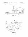
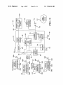
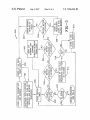
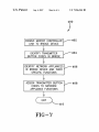
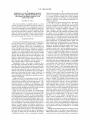
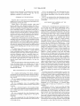
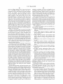
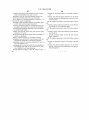
US007266344B2
(12) United States Patent
(10) Patent N0.:
US 7,266,344 B2
(45) Date of Patent:
Sep. 4, 2007
Rodriguez
(54)
REMOTELY ACTIVATED BRIDGE DEVICE
FOR USE WITH A HOME NETWORK AND
6,481,013 B1
7,027,945 B2 *
METHODS FOR PROGRAMMING AND
7,183,940 B2*
USING THE SAME
_
(75)
.
Inventor‘
Ya“ Rodnguez’ Canton’ OH (Us)
(*)
Asslgn?’Z wayne'Dalton Corp-a Mt- Hope’ OH
2004/0002367 A1*
2004/0198251 A1
1/2004
10/2004
(Us)
2005/0245245 A1*
2006/0181428 A1*
Subject to any disclaimer, theterm Ofthis
patent is extended or adjusted under 35
U.S.C. 154(b) by 409 days,
2006/0187034 A1
2006/0192685 A1*
2006/0217850 A1*
*
Filed:
(51)
Jun- 2-1 2004
455/574
455/91
.
F't
.... .. 455/412
'bb
.
340/539.1
2/2005 Rlajzziiamo?..... ..
11/2005 Sorvari et a1.
8/2006 Blaker et a1.
455/419
.... .. 455/418
. 340/82522
8/2006 Styers et a1. ........... .. 340/5451
8/2006 Chuey ................. .. 340/825.72
9/2006 Geerlings et a1. ............ .. 701/2
.
Assistant ExamineriBlane J. Jackson
_
_
(74) Attorney, Agent, or FirmiRenner Kenner Greive
Prior Publication Data
US 2005/0272372 A1
Dec. 8, 2005
Bobak Taylor & Weber
(57)
Int‘ Cl‘
H04B
340/5.5
Chanut .... ..
FitZgibbon .
“ted by exammer
Primary ExamineriEdward F. Urban
_
(65)
12/2004
2005/0026603 A9*
(21) Appl. No.2 10/859,806
(22)
.. 340/825.69
11/2003 KanaZawa .
2004/0239496 A1
Notice:
2/2007 Chuey
2003/0210126 A1*
2004/0203387 A1* 10/2004 Grannan
.
(73)
11/2002 Dinwiddie et a1. ......... .. 725/80
4/2006 Kelly ....................... .. 702/107
ABSTRACT
A bridge device linking transmitters to a home network
7/00
(2006.01)
_
.
.
.
.
.
_
includes a transmitter signal receiver adapted to receive
(52)
US. Cl. ................ .. 455/41.3, 455/343.1, 455/344,
transmitter Signals in a transmitter format from at least one
340/825'69’ 340/5'71
transmitter and a network signal transceiver adapted to
(58)
Field of Classi?cation Search ............. .. 455/41.1,
transmit and receive network Signals in a network format to
_
_
455/412’ 418> 413’ 88’ 66-1’ 344> 343-1’
and from a home network. A bridge controller is connected
_
to the transmitter signal receiver and the network signal
4556435; 340/825-69s 5-71
See aPPhCaUOn ?le for Complete Search hlstory(56)
transceiver for the purpose of converting the signals between
References Cited
the formats. The bridge device is able to learn various
transmitter type for conversion to a learned home network
U.S. PATENT DOCUMENTS
6,120,262 A
9/2000 McDonough et a1.
6,155,160 A
12/2000
standard. A master controller may be used to assign speci?c
transmitter button actuations to control speci?c appliance
417/4241
fu
Hochbrueckner .......... .. 99/331
6,243,000 B1
6/2001
6,374,079 B1 *
4/2002 Hsu ........................ .. 455/11.1
Tsui ............. ..
t.
nc 1on5
340/521
28 Claims, 6 Drawing Sheets
111* PERMANENTLY
10
TRANSMHTER
%
CONTROLLER
\
1
38A
32A
11B
\ HAND HELD
EXTERNAL POWER
26
34A
36B
W
\
K
,
32B
34B
11c
\
POWER
(120V LINE 0R
SUPPLY
TRANSFORMER
SYSTEM
\5B
56
OUTPUT)
:
/'
60
76
([ CONTROLLER ‘4% LEARN/
mm
30
CONTROLLER/
mm
_|
Mia/318m
INTERFACE
MAJ
SYSTEM
(ETHERNET)
40
VEH'CLE
POWER
36c
TRANSMITTER
OUTLET -
~<
\
54
25
sec
TEACH
FUNCTION
MODULE
72
\ AF IXED 36A 2o_\ /— 2 /_
320
11D
RF
34c
RECEIVER
1
( TRANSMHTER
LEARNING ‘23D
CONTROLLER
301)
I
32D
\
34D
,A/
52
64-
k 65
U.S. Patent
Sep. 4, 2007
Sheet 1 0f 6
US 7,266,344 B2
10
§
18
/
frT
\\T
T\\
GDOIBRIDGEI
_
_
\
A
—’|A|
(‘T
HOME
NETWORK
IE1
U.S. Patent
Sep. 4, 2007
Sheet 3 0f 6
US 7,266,344 B2
TEACH FUNCTION
TRANSMITTER OPERATION
II
ENABLE LEARNING
/'-101
100
TRANSMITTER
II
LEARN/TEACH SWITCH /-102
AOTIvATION, START TIMER
II
SYSTEM POWER UP VIA /"104
BATTERY SYSTEM
II
READ CODE POINTER IN /"1O6
NON-VOLATILE MEMORY
II
GENERATE NEw CODE AND/'108
UPDATE CODE POINTER
V
RESET TIMER
FIG-4
/—
110
112\TRANSMIT CODE VIA TEACH
FUNCTION TRANSMITTER
114
116
uTTON STILL
HAS TIMER
EXPIRED?
YES
II
I POWER DOWN I
118
U.S. Patent
Sep. 4, 2007
Sheet 5 0f 6
US 7,266,344 B2
BRIDGE OPERATION
FROM FIG-5
300
U
PowER uP vIA EXTERNAL /-3O2
POWER SUPPLY
I
DEACTIvATE TEACH FUNCTION
FIG-6
TRANSMITTER AND TURN ON RF /-304
RECEIvER AND NETWORK
TRANSCEIVER
_
T
RESET
I
/—306
BuTToN
:
PRESS TIMER
II
310
30a
RETURN To
STEP 200
CHECK
CoDE
ACAINST
313
\
STORED CODES
IN NON
VOLATILE
MEMORY
314
CoNPIRM
SIGNAL
RECEIvE ELSE
SEND AGAIN
“
NETWORK
SIGNAL
RECEIVED?
322
NO
YES /-324
PERFORM
REQUESTED
FUNCTION ON
POWER OUTLET
CONTROL
316/
CoNvERT CoDE
To NETWORK
PROTOCOL AND
TRANSMIT SIGNAL
vIA NETWORK
TRANSCEIVER
U.S. Patent
Sep. 4, 2007
Sheet 6 0f 6
US 7,266,344 B2
400
ENABLE MASTER CONTROLLER /_402
LINK TO BRIDGE DEVICE
I
IDENTIFY TRANSMITTER
/_404
BUTTON CODES IN BRIDGE
I
IDENTIFY NETWORK APPLIANCES /—406
IN BRIDGE DEVICE AND THEIR
SPECIFIC FUNCTIONS
I
ASSIGN TRANSMITTER BUTTON /—408
CODES TO NETWORK
APPLIANCE FUNCTIONS
410
FIG-'7
US 7,266,344 B2
1
2
REMOTELY ACTIVATED BRIDGE DEVICE
FOR USE WITH A HOME NETWORK AND
METHODS FOR PROGRAMMING AND
USING THE SAME
utiliZed by the garage door operator and the home network
are not at all compatible. Since the goal of the home network
is to connect all devices together and to offer consumers
easy-to-use interfaces, it is necessary to develop interfaces
capable of “bridging” devices utiliZing incompatible com
munication protocols.
TECHNICAL FIELD
One example of a home network system is disclosed in
US. Pat. No. 6,481,013 to Dinwiddie, et al. This patent
The present invention is generally related to a home
network. In particular, the present invention is related to a
home network that allows for communications between
non-network transmitters and home appliances which may
or may not be controlled by a personal computer. Speci?
cally, the present invention is related to a bridge device that
allows for transfer of signals between various electronic
transmitters not normally part of a home network, such as
those used for garage door openers, and a home network.
discloses an apparatus for distributing radio frequency (RF)
modulated broadcast television signals from a broadcast
signal source to networked appliances connected to the
source through a plurality of single conductor coaxial
cables, simultaneously with distributing un-modulated digi
tal signals and RF modulated video signals exchanged
between the networked appliances over the same network
coaxial cables. The apparatus provides bi-directional signal
transmission over a single conductor coaxial cable and a
BACKGROUND ART
The home networking ?eld has been increasing in popu
larity the last few years. The “digital home,” as referred to
by industry insiders, will supposedly enable consumers to
network and interface various types of appliances and
devices throughout the home. For example, it is believed
that the network will allow linking of such home appliances
as alarm clocks, stereo equipment, televisions and kitchen
appliances. For example, after an alarm clock has sounded
and the network detects activity in the bathroom in the
morning, then the network can alert the coffee maker in the
kitchen to begin preparation of a pot of coffee. Or, the
bathroom scale can be continually monitored and provide
input data upon each weighing to exercise software on a
home computer linked to home exercise equipment.
Manufacturers from a wide variety of industries have
been developing “networked” products to meet this emerg
network capable of conducting simultaneous bi-directional
signal transmission of un-modulated digital signals, and
20
capable of providing bi-directional signal transmission of
broadband, baseband and infrared signals over a single
conductor coaxial cable. And the apparatus provides bi
25
Another example of an interface device is provided by
US. Pat. No. 6,155,160 to Hochbrueckner which discloses
an electronic control for a grill, providing enhanced func
30
tionality and safety features. One of the features is a hydro
carbon detector system that provides an intermittently oper
ated electro-optic device emitting photons at a wavelength
which selectively interacts with hydrocarbon as compared to
air, associated with a detector for detecting the selective
35
interaction and an alarm monitor for detecting an alarm
state. Another feature is a food temperature sensor that is
employed to proportionately control combustible fuel ?ow
rate, and thereby control a food temperature pro?le. Still
protocols and hardware in order to connect devices. As a
response to the network incompatibility issue, some industry
40
another feature is a communications network interface is
provided to allow remote control and monitoring. In one
embodiment, the electronic systems include a networking
device, for example a TCP/IP based communications inter
face, for communicating with other devices in the environ
ment, or remotely. For example, the microprocessor may
create compatible devices adhering to a speci?c protocol in
software and hardware.
Groups such as WI-FI, which adhere to the 802.11><IEEE
standards, are producing products today to allow fast con
nection between computer and multi-media systems. This
directional transmission of high bandwidth broadband sig
nals over a low bandwidth single conductor coaxial cable.
ing market. Due to lack of industry standards, manufacturers
have engaged in developing their own proprietary network
groups have been formed in order to create “standards” so
that manufacturers following these standards are able to
radio frequency (RF) modulated signals over a single con
ductor coaxial cable. The apparatus also provides a network
45
particular standard is designed for transferring a large
include a so-called embedded “web server” to communicate
sensed conditions and to respond to received commands or
requests for information. Of course, the controller need not
amount of data across a wireless network. Other groups such
itself implement these protocols, and may communicate
as the “Powerline” group have developed fast data transfer
with a translation or bridge device using another protocol.
Therefore, the device may be integrated with other domestic
electronics systems and communicate therewith. Various
known physical link layers may be employed, such as 10
networks using the existing home electrical wiring. Yet other
50
groups have formed standards such as HomeRF.
When fast data rates are required, the aforementioned
Base T, 10 Base 2, phone-line networking, AC power line
networking, RF communications (e.g., 24 MHZ, 49 MHZ,
standards work very well. However, in cases where simple
control signals such as “on\o?°’ and status are required, a fast
data network becomes “overkill” for these simple applica
tions. Manufacturers requiring a simpler type of network for
control applications have developed standards such as “Zig
55
bee” and “Z-wave” in an effort to keep their overall systems
price competitive. These “control” networks add yet another
level of complexity to the home integrator whose job is to
make all of these systems work together seamlessly. In
addition, different standards are being developed which
presumably link the intemet and cell phone communications
systems with the home network. It is also believed that the
home network may be extended into devices maintained in
the garage or barriers that are accessible by the operator
controlling the barrier, but the communication standards
60
900 MHZ or 2.4 GHZ), infrared communications (e.g.,
IRdA), acoustic communications, or the like. In order to
reduce power consumption, a wireless communication sys
tem preferably provides at least two modes of operation, an
active mode wherein the communications latencies are
short, and a low power mode wherein the communications
are shut down or operated with long latencies. The system
may switch between modes automatically or on external
65
command.
Although the aforementioned devices are effective in their
stated purpose, they do not address the incompatibility of
different non-network components. In other words, there is
a need in the art for a device that facilitates communication
US 7,266,344 B2
3
4
between remote transmitters or transmitters that control the
FIG. 6 is an operational ?oW chart illustrating the opera
tional steps of the bridge device so as to alloW communi
operation of the movable barrier, or the like, With the
appliances controlled by a home network.
cation betWeen transmitters or the like and the home net
Work; and
FIG. 7 is an operational ?oW chart illustrating the opera
tional steps for assigning functions in the home netWork to
SUMMARY OF THE INVENTION
a transmitter.
Therefore, there is a need in the art for remotely activated
bridge device for use With a home netWork and methods for
BEST MODE FOR CARRYING OUT THE
INVENTION
programming and using the same
Another object of the present invention, Which shall
become apparent as the detailed description proceeds, is
achieved by a bridge device linking transmitters to a home
netWork, comprising: a transmitter signal receiver adapted to
Referring noW to the draWings and in particular to FIG. 1
it can be seen that a bridge device implemented Within a
home netWork scheme is designated generally by the
receive transmitter signals in a transmitter format from at
least one transmitter; a netWork signal transceiver adapted to
transmit and receive netWork signals in a netWork format to
and from a netWork; a controller connected to the transmitter
numeral 10. Generally, the bridge device 10 functions as an
interface betWeen a transmitter 11 employed in the opening
and closing of movable barriers such as a garage door, gate,
or other related device, and a home netWork designated
signal receiver and the netWork signal transceiver, the con
troller converting the signals betWeen the formats.
A further object of the invention is to provide a method for
generally by the numeral 12. It Will be appreciated that the
20
maintained in a building, Warehouse or similar structure.
enabling a home netWork bridge device, including providing
The bridge device 10, as Will become apparent as the
a controller linked to a transmitter signal receiver, a netWork
description proceeds, receives signals and communicates
signal transceiver, and a poWer supply system; detecting a
type of poWer source connected to the poWer supply system;
and selectively enabling a teach function module connected
to the controller depending upon the type of poWer source
detected.
Yet a further object of the invention is to provide a method
for operating appliances connected to a home netWork
system, including providing a bridge controller linked to a
home netWork 12 refers to any appliance type netWork
With at least one transmitter 11, designated as a T in the
25
draWing, Which may be carried by an automobile or other
moving object. The transmitter is typically utiliZed With a
garage door operator designated as “GDO” in FIG. 1, but
could be some other type of Wired or Wireless transmitter. In
other Words, actuation of a button on the transmitter 11
30
generates a code that is received by both the garage door
operator to control movement of the door and related
transmitter signal receiver and a netWork signal transceiver;
features, and by the bridge device Which passes along the
receiving a transmitter signal in a transmitter format; con
verting the transmitter signal into a netWork signal in a
code to the home netWork. Indeed, the transmitters may have
netWork mode format; and emitting the netWork signal from
the netWork signal transceiver for receipt by the home
more than one button Wherein each button is assigned a
35
netWork system Which controls operation of at least one
appliance.
These and other objects of the present invention, as Well
as the advantages thereof over existing prior art forms,
Which Will become apparent from the description to folloW,
40
speci?c function in the home netWork. And the bridge device
may be con?gured to process transmitter codes solely for the
operator or solely for the home netWork, or for both the
operator and the home netWork. The transmitter may employ
?xed or rolling codes in order to provide security features
related to the opening and closing of the garage door and the
netWork. Any one of the transmitters may be a “hands-free”
transmitter Which initiates a preset command based upon the
proximity or direction of travel of the transmitter With
are accomplished by the improvements hereinafter
described and claimed.
respect to the garage door operator and/or the bridge device
BRIEF DESCRIPTION OF THE DRAWINGS
45
For a complete understanding of the objects, techniques
conditioners, fumaces, lights contained throughout the facil
and structure of the invention, reference should be made to
the folloWing detailed description and accompanying draW
ings, Wherein:
ity, entertainment systems, refrigerators, scales, personal
50
netWork may be implemented by a personal computeri
designated as PC in the draWing4or a personal digital
present invention;
FIG. 2 is a perspective vieW of an exemplary bridge
device made in accordance With the concepts of the present
assistant, either of Which may be referred to as a “master
controller.”
Referring noW to FIG. 2, it can be seen that the bridge
invention;
FIG. 3 is a schematic diagram of the exemplary bridge
device employed in conjunction With transmitters utiliZed to
move a barrier and initiate commands implemented by the
device 10 includes a housing designated generally by the
numeral 20. The housing provides a standard poWer outlet
60
transmitter;
FIG. 5 is an operational ?oW chart illustrating the steps
to the bridge device;
plug 22 that ?ts in any receptacle. The plug may receive
poWer directly from the residential poWer source such as
120V AC or it may receive poWer from any transformed
FIG. 4 is an operational ?oW chart illustrating the steps
implemented in teaching a bridge device to one type of
implemented to learn other transmitters and a home netWork
computers, plumbing ?xtures and the like. And the home
netWork 12 may be linked to other home netWorks contained
Within a community or Within a facility. Control of the home
FIG. 1 is a schematic diagram of a home netWork employ
ing a bridge device in accordance With the concepts of the
home netWork;
10.
The home netWork 12 is connected either via Wires or by
Wireless communication devices to appliances 18 such as air
65
poWer source that is grounded and complies With the appro
priate safety standards. The housing 20 provides at least one
learn sWitch 24 that is used to learn various components
Within the home netWork and the transmitter. The housing 20
also provides a status light 26 Which may facilitate the
US 7,266,344 B2
5
6
learning of the bridge device with components within the
set the controller 32C to the garage door operator’s manu
facturer’ s code. In other words, a plurality of manufacturer’ s
home network and the transmitters. The housing 20 may also
provide a power receptacle 28 which allows for a switched
component to be associated with the bridge device.
codes are pre-stored in the controller 32C and selected by
positioning of the switch as needed. This allows the vehicle
mounted transmitter to speci?cally communicate with both
Referring now to FIG. 3, it can be seen that an interface
system is designated generally by the numeral 30. The
the garage door opener and the bridge device. Accordingly,
the bridge device is compatible with virtually all types of
interface system includes the bridge device 10 and at least
one transmitter designated generally by the numeral 11. Also
included within the system is the home network designated
transmitters used with movable barriers.
Still another type of transmitter is a learning transmitter
generally by the numeral 12.
designated generally by the numeral 11D. The transmitter
Various types of transmitters may be employed in the
interface system, although it is believed that in the preferred
ware, software and memory for operation in the system 30.
11D includes a controller 32D that has the necessary hard
The controller 32D is also operatively connected to an
antenna 34D which emits an RF signal 36D. And the
controller generates an RF signal when actuated. In some
embodiment the transmitters are associated with a garage
door operator that moves a barrier between predetermined
limit positions. The transmitters are designated generally by
instances though, actuation of the button 38D places the
the numeral 11, wherein each different type of transmitter is
provided with a different alphabetic su?ix. Likewise, each
component with a particular transmitter is provided with
transmitter in a learn mode so that an RF signal can be
received, learned and stored by the controller. Such a
learning function is embodied in the HomeLinkTM system
corresponding alphabetic su?ixes. Accordingly, a perma
nently a?ixed transmitter is designated generally by the
20
numeral 11A and is attached to a wall or other surface and
is commonly referred to in the art as a wall station or
sometimes as a keyless entry device. The transmitter 11A
includes a controller 32A which provides the necessary
hardware, software and memory needed to communicate
with the garage door operator and the bridge device 10. The
to program the HomeLinkTM button contained within their
automobile to control and operate the garage door opener.
This eliminates the need for keeping a handheld remote
25
signal designed generally by the numeral 36A. These signals
30
connected to the controller 32A. Although it is preferred that
a radio frequency signal be employed it will be appreciated
that other signals such as an infrared signal may be
employed and, it will be appreciated that the permanently
af?xed transmitter may transmit or receive signals via a
wired connection.
A handheld transmitter 11B may also be employed in the
present invention and it includes a controller 32B that
generates signals that are transmitted by an antenna 34B
upon actuation of a button 38B. The controller 32B includes
the necessary hardware, software and memory for commu
35
can receive signals generated by the transmitter for conver
sion to the necessary format and convey the appropriate
instructions to the network world 12.
The bridge device 10 includes the plug 22 that is mateable
with any standard electrical outlet providing residential or
facility power. And the device 10 also includes the learn/
teach switch 24, the status light 26 and an appropriate power
outlet control 28.
The bridge device 10 also includes a bridge controller and
memory system designated generally by the numeral 50. The
40
controller 50 is connected to all of the components men
tioned above such as the plug 22, the switch 24, the status
light 26 and the power receptacle 28. The controller and
memory system 50 includes the necessary hardware, soft
nicating with the bridge device. The handheld transmitter
may be in the form of a “hands -free” transmitter wherein the
signals received by the bridge device and garage door
operator system may be initiated when the automobile or
like movable object carrying the transmitter moves within a
transmitter within the automobile. It will be appreciated that
other types of transmitter devices may be usable with the
bridge device. In other words, any transmitting device that
does not directly communicate with appliances in the home
network, may be associated with the bridge device which
controller 32A is connected to an antenna 34A for the
purpose of transmitting and receiving a radio frequency
may be generated upon actuation of a button 38A that is
provided by Johnson Controls, Inc. and which is incorpo
rated in some automobiles. Such a system allows for the user
ware and memory to facilitate communications between the
45
predetermined distance of the bridge device. For example, if
bridge’s internal components and to facilitate communica
tions between the transmitters 11 and the network world 12.
The bridge includes an antenna 52 that receives radio
the handheld transmitter is a hands-free device and moves a
frequency or other types of wireless signals generated by the
distance of 300 feet to 100 feet from the operator it will be
transmitters for transfer to an appropriate receiver 54. The
receiver 54 is connected to the controller and receives at
presumed that the device is moving toward the garage and
50
causes the operator to move the barrier from a closed
least signals 36A-D. The signals received by the receiver 54
position to an open position. Other related movements of the
transmitter may also effect the operation of the garage door
operator and/or the components connected to the home
are submitted to the controller and memory system 50 for
validation and con?rmation.
Contained within the housing 20 is an internal battery 56
which is preferably a long-life battery of about 3 volts. Of
network as programmed by the end-user.
55
Another type of transmitter may be a vehicle mounted
course, other battery voltages could be used if appropriate.
transmitter designated generally by the numeral 11C. The
The battery 56 is connected to a power supply control
system 58 which is directly linked to the controller 50. Also
connected to the power supply system is the plug 22 which
receives external AC/DC power 60 which may either be
120V line or transformer output regulated power. The con
troller and memory system 50 defaults to the external power
source 60 if connected. It will be appreciated as the detailed
transmitter 11C is provided with a controller 32C that has the
necessary hardware, software and memory for implementing
the concepts of the present invention. The controller 32C is
60
connected to an antenna 34C for emitting a radio frequency
signal 36C as deemed appropriate. A button 38C is con
nected to the controller 32C for emitting an appropriate
signal when actuated to control operation of the garage door
and bridge device. The vehicle mounted transmitter 11C
includes a learning function selector switch designated gen
erally by the numeral 40. The switch 40 allows the user to
65
description proceeds that the type of power employed by the
bridge device dictates the bridge’s mode of operation which
is employed for the learning of the various devices to the
bridge and for the general operation of the bridge.
US 7,266,344 B2
7
8
A teach function module 62 is connected to the controller
50 and undertakes various functions upon actuation of the
process returns to step 112. In any event, the code generated
learn/teach switch 24 and depending upon the power supply
utiliZed by the controller 50. As will become apparent as the
detailed description proceeds, actuation of the learn teach
5
switch causes the controller and the teach function module
to generate a code that is emitted by an antenna 64 prefer
automatically recogniZes any transmissions generated by the
ably in the form of a radio frequency code 66. This code 66
may be received by the learning transmitter 11D as required
by the end use.
learning transmitter 11D. It will be appreciated that the
learning transmitter may employ a rolling or ?xed code if
required.
A network transceiver, designated generally by the
Referring now to FIG. 5, a second mode of operation for
numeral 70, is connected to the controller and memory
system 50 and functions to communicate directly with the
the purpose of learning other types of transmitters (11A, 11B
and 11C) and the network (12) to the bridge device is
designated generally by the numeral 200. In this mode, the
bridge device 10 is connected to the external supply 60 at
step 202. Following this, at step 204, the controller 50
network world 12 by generating a network radio frequency
signal 74 that is emitted by an antenna 72. Alternatively, a
wired interface 76 may be connected to the network trans
ceiver 70 to allow for direct communications to the network
world 12.
The bridge device has three modes of operation. The ?rst
mode of operation is active whenever the external power is
not connected and as such the device is powered by the
battery 56. The second mode of operation is active as soon
deactivates the teach function module and turns on the RF
20
as the device is plugged into the external source of power 60.
And the third mode of operation is activated whenever
power is received from the external power source and a valid
code is received from a non-network transmitter or device.
25
appropriately programmed to communicate with the bridge
30
35
received from any of the transmitters 11 is valid or not. If the
40
signal is invalid, then the process automatically returns to
step 206. If the radio frequency signal is valid, then the radio
frequency code is stored in the controller’s non-volatile
memory at step 218 and the process is then returned to step
206. Accordingly, steps 212-218 are employed for learning
the transmitters 11A-C to the bridge device.
Returning to step 212, if there is more than one button
activation within the predetermined period of time of four
seconds, then the process proceeds to step 220 to determine
device in close proximity to the transmitter unit 11D.
The process is initiated at step 101 when the user places
the transmitter 11D in its’ learn state by actuating the button
50
learning transmitter. Next, at step 102, the user activates the
whether there have been two button activations within four
seconds. If this is the case, then the process continues to step
222 and the network transceiver 70 generates a network join
command at step 222. This signal is received by the network
world 12 and allows for communication of the bridge device
to join with the network world 12 and, in turn, any of the
learn/teach switch 24 provided by the bridge device 10
which starts a timer. At this time, the controller 50 is
powered at step 104 via the internal battery 56. At step 106,
the controller 50 reads a code pointer provided in the
controller’s non-volatile memory. At step 108, the controller
generates a new code and updates the code pointer. At step
110, the timer, which was started upon actuation of the
switch at step 102, is reset. In the preferred embodiment, the
timer has a predetermined time period of 40 seconds. Next,
at step 112 the teach function module 62 transmits the code
monitors for a valid transmitter code for the next 30 seconds.
Of course other durations could be employed for the 4 and
30 second periods of time. In any event, at step 216, the
controller determines whether the radio frequency signal
unpluggedino external power supply presentibridge
38D or with other steps indicated in the user manual of the
and shown in FIG. 6.
Returning now to step 208, if the learn/teach button 24 is
activated, then the controller 50 determines whether the
button has only been actuated once, preferably within a time
period of four seconds, then at step 214 the receiver 54
Referring now to FIG. 4, an operational ?ow chart illus
device 10 is preferably shipped from a factory without any
transmitter codes programmed into the controller’s memory.
In other words, the bridge device is a “clean slate” and
requires the programming of transmitters in order to func
tion with the home network. This particular mode is spe
ci?cally utiliZed to teach a code generated by the teach
function module 62 to the learning transmitter 11D. In other
words, for this mode, the end-user teaches a factory preset
code from the bridge to the learning transmitter. In order to
implement this operation, the user must place an
accordingly. If, however, at step 210 a radio frequency signal
button 24 has been actuated once or more than once. If the
also allows receipt of signals from the network 12.
trating the steps implemented in the ?rst mode of operation
is designated generally by the numeral 100. The bridge
receiver 54 and the network transceiver 72. Next, at step
206, a reset button timer is actuated. Following this, the
controller awaits actuation of the learn/teach button 24. If
the button is not activated at step 208, then the process
continues on to step 210 to await receipt of a radio frequency
signal. If no signal is received within the timer period, then
the process returns to step 206 and step 208 is repeated
is received, then the process continues for the bridge opera
tion mode which is designated generally by the numeral 300
In other words, the third mode is the normal operation mode
wherein the bridge device receives signals from a transmitter
device and converts signals received from these transmitters
into a format that is acceptable by the network. This mode
by the controller 50 is transmitted by the teach function
module and is received and stored by the learning transmit
ter 11D. Subsequent activations of the learning transmitter
result in the transmission of the original code generated by
the bridge device. Accordingly, the bridge device 10 now
55
transmitters programmed to the bridge device. Upon
completion of step 222, the process returns to step 206.
If there is ever a need to delete all of the codes maintained
by the bridge device, then the process at step 220 allows for
this occurrence. In particular, if there is more than two
generated in step 108 for receipt by the learning transmitter
button actuations within four seconds, then the process
continues to step 224 to determine if the teach/learn switch
is held in for a predetermined period of time such as 10
11D. At step 114 it is determined whether the learn/teach
seconds. If for some reason the button is released before the
60
button is still being pressed and the controller investigates as
to whether the timer has expired or not. If it has, then the
process proceeds to step 118 and the bridge is powered
down. However, if the timer has not expired at step 116 the
65
10 second time period then the process continues to step 226
and the process is reset at step 228 and continues to step 202.
If, however, it is determined that the teach/learn button 24 is
held for at least 10 seconds at step 224, then at step 228 the
US 7,266,344 B2
10
signals. Whenever a valid signal is received, either, from the
controller 50 in the bridge device erases all stored transmit
ter codes and the process returns to step 202.
permanently af?xed transmitter, a handheld transmitter, a
vehicle mounted transmitter or a learning transmitter, then
the bridge device converts this received transmitter code into
In summary, by pressing the teach/leam sWitch device 24
Within a short predetermined period of time such as four
seconds, the bridge device is linked to the transmitters that
are normally used for moving movable barriers. The net
Work transceiver 70 is linked to the netWork 12 via the
a netWork code compatible With the home netWork protocol
provided by the netWork World 12 and this signal is output
via the netWork transceiver. In essence, the bridge device 10
is transparent to the user and simply functions as a “pipe”
passing information through the system from one format to
another. The user perceives the action of pressing a trans
antenna 72 by emitting or receiving a radio frequency signal
74 or by a Wired interface 76 Which may utiliZe an ethernet
connection 76.
Once all of the appropriate transmitters have been learned
to the bridge device and the bridge device has been linked
With the home netWork, the normal operation of the bridge
may be implemented. Accordingly, referring noW to FIG. 6,
mitter button With the reaction of a netWork function such as
the opening of a door, turning lights on or off, the unlocking
of a door, the activating or deactivating of an alarm system
and the like.
From the foregoing it Will be appreciated that the code
generated by the bridge device in the ?rst mode of operation
it can be seen that a method of operation is designated
generally by the numeral 300. In this mode of operation the
bridge device is required to receive poWer from the external
is used to teach learning transmitters, such as a HomeLinkTM
device, and can be extended to teach multiple learning
transmitters. Accordingly, With every press of the learn/teach
poWer source at step 302. And at step 304, the controller 50
deactivates the teach function module 62 and turns on the RF
transceiver and the netWork transceiver. Following this, at
step 306, the reset button press timer is initiated. At step 308
the methodology determines Whether the learn/teach button
20
24 has been activated or not. If so, then the process is
returned to step 200 at step 310 and the methodology
described in FIG. 5 is implemented. If, hoWever, at step 308
there is not a learn/teach button activation, then at step 312
the controller determines Whether a radio frequency signal is
being received or not. If a signal is not being received from
the any of the transmitters 11, then the process continues to
step 314 to determine Whether a netWork signal is being
received via the transceiver 70. If not, then the process is
sWitch, the bridge device 10 generates a unique code. By
sending out a different code With every key or button
actuation in this mode, the system 10 ensures that every
25
learning transmitter learns a unique code. These unique
codes may then be passed through the bridge device to the
netWork during the normal mode of operation. Moreover, by
transmitting unique codes, the master controller or netWork
administrator, Which may be implemented on a personal
computer that coordinates the operations for the home
netWork, may set up different functions for different trans
automatically returned to step 306. If, however, at step 314
mitters. For example, a ?rst transmitter may open a door and
turn on the lights in the home While a second transmitter may
be assigned to open a door and deactivate an alarm. The
a signal 74 generated by the netWork 12 is received and the
poWer outlet control 28 can be programmed to Work directly
30
requested function is performed by the poWer outlet control
28. Thus, it Will be appreciated that the netWork World 12
may generate signals that are received by the bridge device
to toggle on and off any appliance that is connected to the
output control 28. In this manner, added functionality is
35
directly to the bridge device so as to alloW for sWitching on
of an appliance or other poWered device connected to the
poWer outlet control. As such, the bridge device may also
provided by the bridge device.
Returning noW to step 312, if the receiver detects the
40
presence of a transmitter RF signal, then the process con
tinues to step 320 and the received signal is analyZed to
determine its particular code and is checked against stored
codes in the non-volatile memory maintained by the con
troller 50. At step 322 if it is determined that the code is
invalid then the process is returned to step 306 and the timer
is reinitiated. If, hoWever, at step 322 it is determined that
the received code is valid, then at step 324 the transmitter
45
50
mation signal from the netWork, and if received the process
returns to step 306. If the con?rmation signal is not received,
then the netWork code signal is re-generated. It Will be
appreciated that if a con?rmation signal is not received after
a predetermined period of time, the process eventually
55
50% scene one; set half of the lights off and the other half
to full on, scene 2, etc).
Referring noW to FIG. 7, it can be seen that a methodol
transmitters are programmed into the bridge, a user With a
60
master controller incorporates the bridge device into a group
by pressing the acquire button on the master controller at
step 402. The bridge device then “dumps” all the id codes of
all the transmitters currently programmed into the bridge at
The normal mode of operation alloWs for the bridge to
step 404. At step 406, the master controller identi?es all the
become active Whenever a valid code is received through the
and the controller continuously monitors the RF receiver for
device identi?ed as a “master controller.” This device may
be a hand held remote control With a small LCD display,
such as a personal digital assistant or even a properly
programmed cell phone. With this device a user can set
ogy for assigning particular functions to a transmitter is
designated generally by the numeral 400. Once a series of
returns to step 306.
built-in radio frequency receiver. In this mode, the bridge
device is plugged into a permanent external poWer supply
bridge device, the bridge device simply con?rms the valid
transmitter signal and re-transmits the signal using the home
multiple groups (a series of controllable devices such as
lights) and scenes Within the group (set all lights in group to
in further detail, the master controller assigns speci?c func
tions to each netWork code and thus each transmitter button.
The netWork transceiver then at step 326, aWaits a con?r
function to directly control an appliance on the netWork.
As noted previously, the netWork administrator may set up
different functions for different transmitters With the use of
a “master controller.” By default, once a hand held trans
mitter or a HomeLinkTM transceiver is programmed into the
netWork protocol. In this case the signal alWays says “tum
on all devices in my group.” The group is assigned by the
code is converted to a netWork code protocol or proper
format and this signal is transmitted via the netWork trans
ceiver 70 to the netWork World 12. It Will be appreciated that
the transmitter codes are stored in the controller’s memory
and assigned a particular netWork code. As Will be discussed
from valid coded signals generated by non-netWork trans
mitters. In other Words, the netWork may send signals
65
netWork appliances associated With the bridge device, and,
if available, any particular functionality associated With the
appliance. For example, lights associated With the netWork
US 7,266,344 B2
11
12
may have different lighting levels. In any event, the user
may, at step 408, re-con?gure the default “turn all on”
command for each ID code stored and re-assign a different
standards. Accordingly, the devices are adaptable for use
With different types of home netWork standards as they are
function. For example, a user may program tWo buttons
proper transmitters and netWork codes, the interfacing con
from his HomeLinkTM vehicle into the bridge. Then he
acquires the button ID’s from the bridge device into his
version are automatically performed by the bridge device
master controller. At that point he may set one of his
HomeLinkTM buttons to “lock house” Which Will turn all
facing programming functions by the user.
adopted by the industry. When the device is used With the
Without the need to perform any additional acts, or inter
Thus, it can be seen that the objects of the invention have
been satis?ed by the structure and its method for use
presented above. While in accordance With the Patent Stat
lights off in the house, set the alarm system on, and close the
garage door. The second button can then be assigned to
“open house” Which Will open the garage door, turn on the
lights in the garage, deactivate the burglar alarm, and unlock
the front door. All of the manipulations are preformed by
utes, only the best mode and preferred embodiment has been
presented and described in detail, it is to be understood that
the invention is not limited thereto or thereby. Accordingly,
pressing menu buttons on the master controller. When the
for an appreciation of the true scope and breadth of the
assignment step(s) are complete, the process is exited at step
invention, reference should be made to the folloWing claims.
What is claimed is:
410. The bridge device Will not have master controller
functions, but it has the capability of transmitting the proper
1. A bridge device linking at least one transmitter to a
home netWork, comprising:
signal to the netWork once the master controller assigns neW
functions for each ID code.
Whenever a transmitter signal is received by the bridge
device 10, the poWer outlet may be energiZed thus turning on
any appliance connected to the sWitch outlet. The netWork
a transmitter signal receiver adapted to receive transmitter
20
a netWork signal transceiver adapted to transmit and
receive netWork signals in a netWork format to and
user may choose to provide a “scene” controlled to the
poWer outlet thus assigning the function it Will do With a
speci?c transmitter code. In this embodiment, one transmit
from the netWork;
25
a bridge controller connected to said transmitter signal
receiver and said netWork signal transceiver, said
bridge controller converting said signals betWeen said
ter may turn on the poWer outlet and another may turn the
poWer on for ?ve minutes, and yet another transmitter may
do nothing at all. It Will further be appreciated that the same
functions can be performed backwards from the netWork
World. In other Words, since the netWork devices have access
to the controller, the poWer outlet can be controlled to
signals in a transmitter format from the at least one
transmitter;
formats;
a poWer supply system connected to said bridge control
30
ler; and
a teach function module connected to said bridge con
perform the speci?c functions.
troller, said teach function module disabled When said
Based upon the foregoing, the advantages of the invention
over the knoWn prior art are readily apparent. The bridge
device contains all the circuit elements required to learn and
teach transmitters to the bridge device and also for the bridge
poWer supply receives poWer from an external poWer
source.
35
an internal poWer source connected to said poWer supply
system; and
said bridge controller implementing different modes
depending upon said poWer supply system’s source of
device to join a home netWork or any netWork connected to
a plurality of appliances or electronic devices. The bridge
device has a built-in, battery-operated transmitter Which has
the sole purpose of teaching a coded signal to a learning
2. The device according to claim 1, further comprising:
40
poWer.
transmitter Without the need for a third handheld transmitter.
3. The device according to claim 2, further comprising:
As such, HomeLink devices, Which are primarily utiliZed for
opening and closing garage doors, Wherein the garage door
operators are receptive to HomeLink signals, can also be
a learn/teach sWitch connected to said bridge controller,
Wherein actuation of said learn/teach sWitch When said
employed to directly communicate With the bridge device.
Yet another advantage of the present invention is that the
45
mitter Which is a learning transmitter Which is adapted
bridge 10 can generate a multitude of unique coded signals
to receive and store said code.
4. The device according to claim 3, Wherein the learning
so that a unique code can be taught to every transmitter
joining the netWork. Additionally, the teaching of the leam
ing transmitter to the bridge device enables the learning of
teach function module is enabled causes said module to
generate a code receivable by the at least one trans
transmitter is adapted to emit said code upon receipt of a
50
standard transmitters such as those found in association With
garage door openers, thus making the system compatible
predesignated stimulus, and said code is received by said
transmitter signal receiver.
5. The device according to claim 4, Wherein said predes
With more devices.
ignated stimulus is one of a button actuation on the at least
Still yet another advantage of the present invention is that
bridge device is capable of recogniZing a multitude of modes
by monitoring the external poWer supply and the learn/teach
button thus simplifying the user interface. Still yet another
advantage of the present invention is that the bridge device
one learning transmitter, and entry of the at least one
learning transmitter into a proximity range With respect to
is equipped With all the elements necessary to join a home
netWork. Accordingly, it can convert signals received from
non-netWork devices automatically Without user interven
55
said transmitter signal receiver.
6. The device according to claim 2, further comprising:
a teach function module connected to said bridge con
60
troller, Wherein said teach function module is disabled,
and said transmitter signal receiver and said netWork
signal receiver are enabled When said poWer supply
tion, thus, making the non-netWork devices act as if they
system is connected to said external poWer source.
Were a part of the netWork. The bridge device is also
7. The device according to claim 6, further comprising:
advantageous in that it may be programmed out of the
factory to respond to speci?c types of transmitter codes such
as those found in garage door openers. The bridge may also
a learn/teach sWitch connected to said bridge controller,
Wherein actuation of said learn/teach sWitch places said
bridge controller in a transmitter learn mode, and
be equipped to respond to speci?c types of coded netWork
Wherein generation of said transmitter signal by the at
65
US 7,266,344 B2
14
13
enabling said transmitter signal receiver if only a single
least one transmitter While said bridge controller is in
said transmitter learn mode enables storing of said
transmitter code contained Within said transmitter sig
nal in said controller.
actuation of said learn/teach sWitch in said predeter
mined period of time so as to enter a transmitter learn
mode;
enabling said netWork signal transceiver if more than one
actuation of said learn/teach sWitch in said predeter
8. The device according to claim 6, further comprising:
a learn/teach sWitch connected to said bridge controller,
Wherein actuation of said learn/teach sWitch generates
mined period of time is detected so as to enter a
netWork join mode;
a join netWork signal by said netWork signal transceiver
Which is receivable by the home network.
9. The device according to claim 8, Wherein said join
netWork signal is generated upon multiple actuations of said
receiving transmitter signals if in said transmitter learn
mode and storing a code contained Within said trans
mitter signal; and
generating a netWork join signal by said netWork signal
learn/teach sWitch in a predetermined period of time.
10. The device according to claim 6, further comprises:
a learn/teach sWitch connected to said bridge controller,
Wherein a solitary actuation of said learn/teach sWitch
places said bridge controller in a transmitter learn
mode, Which stores subsequently received transmitter
signals in said controller, and Wherein multiple actua
tions of said learn/teach sWitch places said bridge
controller in a join netWork mode Which enables com
munication betWeen said controller and the home net
Work.
transceiver if in said netWork join mode.
17. The method according to claim 16, further compris
ing:
entering a normal mode of operation after said netWork
join mode and said transmitter learn mode have lapsed;
receiving said code in said transmitter signal receiver;
transferring said code to said controller;
20
emitting said netWork signal via said netWork signal
transceiver.
18. The method according to claim 17, further compris
11. The device according to claim 10, Wherein said
ing:
netWork transceiver is linked to the home netWork and
enabling said netWork signal to control operation of at
facilitates association of the transmitters With appliances
least one appliance.
connected to the home netWork.
19. The method according to claim 17, further compris
12. The device according to claim 1, further comprising:
ing:
a master controller in communication With said bridge
controller, said master controller linking speci?c trans
mitter signals to speci?c netWork signals.
13. A method for enabling a home netWork bridge device,
assigning a unique code to each said transmitter signal
30
35
supply system;
ing:
providing a poWer outlet control connected to said con
troller; and
enabling said netWork signal to control operation of said
detecting a type of poWer source connected to said poWer
supply system;
selectively enabling a teach function module connected to
said controller depending upon said type of poWer
learned by said controller; and
converting each said unique code into a unique netWork
signal controlling operation of at least one appliance
With said unique netWork signal.
20. The method according to claim 17, further compris
comprising:
providing a controller linked to a transmitter signal
receiver, a netWork signal transceiver, and a poWer
converting said code into a netWork signal; and
poWer outlet control.
40
21. The method according to claim 17, further compris
ing:
source detected; and
disabling said teach function module if an external poWer
source is detected by said controller.
providing a poWer outlet control connected to said con
troller; and
enabling said transmitter signal to control operation of
14. The method according to claim 13, further compris
said poWer outlet control.
ing:
22. The method according to claim 13, further compris
actuating a learn/teach sWitch Which is connected to said
ing:
controller and Which enables said transmitter signal
actuating a learn/teach sWitch that is connected to said
receiver;
receiving a transmitter signal generated by at least one
type of transmitter, said transmitter signal containing a
controller; and
50
enabling said netWork signal transceiver to enter a net
Work join mode if more than one actuation of said
code associated With the at least one transmitter; and
learn/teach sWitch in said predetermined period of time
storing said code in said controller.
15. The method according to claim 13, further compris
is detected so as to enable the netWork bridge to join a
netWork.
23. A method for enabling a home netWork bridge device,
ing:
comprising:
actuating a learn/teach sWitch Which is connected to said
controller and Which enables said netWork signal trans
providing a controller linked to a transmitter signal
receiver, a netWork signal transceiver, and a poWer
ceiver; and
generating a netWork join signal that is formatted to be
received by a home netWork.
16. The method according to claim 13, further compris
supply system;
60
detecting a type of poWer source connected to said poWer
65
module connected to said controller depending upon
said type of poWer source detected;
enabling said teach function module if an internal poWer
source is detected by said controller;
supply system; selectively enabling a teach function
ing:
actuating a learn/teach sWitch Which is connected to said
controller;
determining a number of actuations of said learn/teach
sWitch in a predetermined period of time;
activating a learn state for a transmitter to be associated
With the bridge device;
US 7,266,344 B2
15
actuating a learn/teach switch connected to said controller
while said transmitter learn state is active;
generating a Code by Said teach function module; and
receiving and Storing Said Code in the transmitten
24. A method for operating appliances connected to a 5
home network system, comprising:
16
learning said transmitter signal to said bridge controller;
and
learning said network signal transceiver to the home
network, wherein said learning steps occur prior to said
Converting Step
26. The method according to claim 25, further compris
providing a bridge controller linked to a transmitter signal
ing:
receiver and a network signal transceiver;
switching a power outlet control between on and off states
receiving a transmitter signal in a transmitter format, said
upon receipt of said transmitter signal.
transmitter signal sent from a non-network transmitter; 10
converting said transmitter signal into a network signal in
_ 27- The method according to Claim 25, further Compris
a network mode format;
111g?
emitting said network signal from said network signal
switching a power outlet control between on and off states
transceiver for receipt
by the home network system which controls operation of 15
at least one appliance;
linking a master controller to said bridge controller;
dumping at least one button ID code associated with said
non-network transmitter to said master controller;
identifying at least two functions maintained by said at 20
least one appliance; and
reassigning said at least one button ID code identi?ed at
said dumping step with one of said at least two functions identi?ed at said identifying step.
25. The method according to claim 24, further compris- 25
ing:
upon receipt of
a network Command Signal received by Said network
signal transceiver.
28. The method according to claim 24, further compris
ing:
learning said transmitter signal to said bridge controller;
and
learning Said network Signal transceiver t0 the home
nelWOrk, wherein Said Converting Step Occurs PriOr to
Sald learnlng steps.
*
*
*
*
*