1
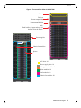
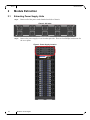
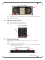
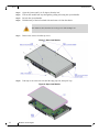
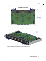
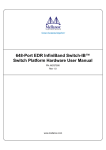
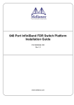
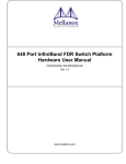
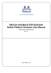
648-Port EDR InfiniBand Switch-IB™
Switch Dismantling Guide
PN: MCS7500
Rev 1.0
www.mellanox.com
Rev 1.0
2
Mellanox Technologies
Document Number: MLNX-15-5427
Rev 1.0
Table of Contents
Revision History . . . . . . . . . . . . . . . . . . . . . . . . . . . . . . . . . . . . . . . . . . . . . . . . . . . . . . . . . . . 5
About this Manual . . . . . . . . . . . . . . . . . . . . . . . . . . . . . . . . . . . . . . . . . . . . . . . . . . . . . . . . . 6
Policy Statement . . . . . . . . . . . . . . . . . . . . . . . . . . . . . . . . . . . . . . . . . . . . . . . . . . . . . . . . . . . 7
Chapter 1 Dismantling. . . . . . . . . . . . . . . . . . . . . . . . . . . . . . . . . . . . . . . . . . . . . . . . . . . . . 8
1.1
General Information. . . . . . . . . . . . . . . . . . . . . . . . . . . . . . . . . . . . . . . . . . . . . . . . 8
Chapter 2 Module Extraction . . . . . . . . . . . . . . . . . . . . . . . . . . . . . . . . . . . . . . . . . . . . . . 10
2.1
2.2
2.3
2.4
2.5
Extracting Power Supply Units . . . . . . . . . . . . . . . . . . . . . . . . . . . . . . . . . . . . . .
Extracting Chassis Fan Units. . . . . . . . . . . . . . . . . . . . . . . . . . . . . . . . . . . . . . . .
Extracting Leaf Modules . . . . . . . . . . . . . . . . . . . . . . . . . . . . . . . . . . . . . . . . . . .
Extracting Spine Modules . . . . . . . . . . . . . . . . . . . . . . . . . . . . . . . . . . . . . . . . . .
Extracting Management Modules . . . . . . . . . . . . . . . . . . . . . . . . . . . . . . . . . . . .
10
11
11
14
16
Chapter 3 Board Extraction from the Chassis Body . . . . . . . . . . . . . . . . . . . . . . . . . . . 21
Mellanox Technologies
3
Rev 1.0
List of Figures
Figure 1:
Front and Rear View of the CS7500 . . . . . . . . . . . . . . . . . . . . . . . . . . . . . . . . . . . . . . . . .9
Figure 2:
AC Inlets . . . . . . . . . . . . . . . . . . . . . . . . . . . . . . . . . . . . . . . . . . . . . . . . . . . . . . . . . . . . . .10
Figure 3:
Power Supply Location . . . . . . . . . . . . . . . . . . . . . . . . . . . . . . . . . . . . . . . . . . . . . . . . . .10
Figure 4:
Power Supply Unit . . . . . . . . . . . . . . . . . . . . . . . . . . . . . . . . . . . . . . . . . . . . . . . . . . . . . .11
Figure 5:
Leaf Fan Module . . . . . . . . . . . . . . . . . . . . . . . . . . . . . . . . . . . . . . . . . . . . . . . . . . . . . . .11
Figure 6:
Releasing Leaf Ejector Handles . . . . . . . . . . . . . . . . . . . . . . . . . . . . . . . . . . . . . . . . . . . .11
Figure 7:
Open Leaf Module . . . . . . . . . . . . . . . . . . . . . . . . . . . . . . . . . . . . . . . . . . . . . . . . . . . . . .12
Figure 8:
Open Leaf Module . . . . . . . . . . . . . . . . . . . . . . . . . . . . . . . . . . . . . . . . . . . . . . . . . . . . . .12
Figure 9:
Open Leaf Module . . . . . . . . . . . . . . . . . . . . . . . . . . . . . . . . . . . . . . . . . . . . . . . . . . . . . .13
Figure 10: Pulling Out the PCB Boards From the Leaf Module . . . . . . . . . . . . . . . . . . . . . . . . . . . .13
Figure 11: Releasing Spine Ejector Handles . . . . . . . . . . . . . . . . . . . . . . . . . . . . . . . . . . . . . . . . . . .14
Figure 12: Removing Spine Fan Modules . . . . . . . . . . . . . . . . . . . . . . . . . . . . . . . . . . . . . . . . . . . . .14
Figure 13: Opening Spine Module . . . . . . . . . . . . . . . . . . . . . . . . . . . . . . . . . . . . . . . . . . . . . . . . . . .15
Figure 14: Removing Spine Module PCB Board . . . . . . . . . . . . . . . . . . . . . . . . . . . . . . . . . . . . . . . .15
Figure 15: Releasing Management Ejector Handles . . . . . . . . . . . . . . . . . . . . . . . . . . . . . . . . . . . . .16
Figure 16: Opening Management Module Cover . . . . . . . . . . . . . . . . . . . . . . . . . . . . . . . . . . . . . . .16
Figure 17: Removing Air Wing Divider . . . . . . . . . . . . . . . . . . . . . . . . . . . . . . . . . . . . . . . . . . . . . .17
Figure 18: Removing Management Module’s Inner Cables . . . . . . . . . . . . . . . . . . . . . . . . . . . . . . .17
Figure 19: Removing Management Module Faceplate . . . . . . . . . . . . . . . . . . . . . . . . . . . . . . . . . . .18
Figure 20: Removing Management Module Bottom Cover . . . . . . . . . . . . . . . . . . . . . . . . . . . . . . .18
Figure 21: Removing Management Module Support Beam . . . . . . . . . . . . . . . . . . . . . . . . . . . . . . .19
Figure 22: Removing Management Module PCB Board . . . . . . . . . . . . . . . . . . . . . . . . . . . . . . . . . .19
Figure 23: Removing Management Module PCB Board . . . . . . . . . . . . . . . . . . . . . . . . . . . . . . . . . .20
4
Mellanox Technologies
Rev 1.0
Revision History
Table 1 - User Manual Revision History
Rev
1.0
Date
05 August 2015
Description
First release
Mellanox Technologies
5
Rev 1.0
About this Manual
This manual is intended as a reference for dismantling the Switch-IB™ based InfiniBand
CS7500 director switch in preparation of meeting the requirements of WEEE recycling.
Intended Audience
This manual is intended for technicians who dismantle the switch systems as a reference for
WEEE recyclers.
Mellanox Technologies emphasizes the importance of carefully following all procedures
described in this guide to prevent personal injury.
6
Mellanox Technologies
Rev 1.0
Policy Statement
Mellanox Technologies recognizes the importance of developing connectivity solutions that not
only enable our customers to optimize their data centers performance, but also protect the environment and ensure that future generations enjoy its bounties. Mellanox Technologies is committed, therefore, to meeting the requirements of the European Union’s WEEE (waste electrical and
electronic equipment) directive. The directive mandates how the materials used in electrical and
electronic equipment must be disposed of.
Mellanox Technologies has worked closely with its suppliers to eliminate hazardous materials
from its products. There are instances, however, where it has not proven possible to completely
eliminate all hazardous materials. Consequently, all applicable products are labeled with a
crossed out “wheelie” bin symbol, indicating that special care must be applied to their disposal
and / or recycling.
Director Switch Systems – RoHS
The chassis switch systems comply with the RoHS directive under the exemption known as
RoHS-6.
All switch systems comply with the RoHS directive under the exemptions known as RoHS-6.
The RoHS exemptions are an integral part of the OPN.
Mellanox Technologies
7
Rev 1.0
1
Dismantling
Dismantling
This document provides detailed instructions for dismantling the InfiniBand chassis switch systems. Follow the instructions in the order they are presented.
1.1
General Information
The switch system is assembled using screws, and modules with handles, snaps and latches.
To disassemble the switch system parts you will need a small Phillips screwdriver and a medium
slotted screwdriver. A screw gun is highly recommended as the larger chassis can have more than
300 screws.
The pictures displayed in the following pages provide visual guidance explaining how to remove
the modules from the mechanical base.
Chassis switch systems are comprised of:
8
•
Leaf modules
•
Spine modules
•
Management modules
•
Fan modules
•
Power supply modules
•
Chassis body
Mellanox Technologies
Rev 1.0
Figure 1: Front and Rear View of the CS7500
AC inlets
Fuse box
(Do not tamper with)
Management Modules
Leafs
Each leaf has 36 ports and up to 18
leafs can fit in the chassis
Power supplies
Chassis fan modules
Spines
AC inlets: 10
Power supply units: 10
Management modules: 2
Spine modules: 18
Leaf modules: 18
Chassis fan modules: 20
Mellanox Technologies
9
Rev 1.0
Module Extraction
2
Module Extraction
2.1
Extracting Power Supply Units
Step 1.
Remove all of the power cords from the back side of chassis.
Figure 2: AC Inlets
Step 2.
Remove the power supply covers from the spine side. There are four Phillips head screws for
the cover plates.
Figure 3: Power Supply Location
10
Mellanox Technologies
Rev 1.0
Figure 4: Power Supply Unit
Handle
Latch
2.2
Step 3.
Grasping the handle with one hand, push the black latch release while pulling the handle outward.
Step 4.
Remove all of the PSUs.
Extracting Chassis Fan Units
Step 1.
Push and hold the blue latch release. See Figure 5.
Step 2.
Slowly pull out the fan module using the handle.
Figure 5: Leaf Fan Module
Latch
Release
Handle
2.3
Extracting Leaf Modules
Each leaf module has ejectors that lock the module in place and serve as a lever for seating or
extracting.
Step 1.
Disconnect all cables connected to the leaf.
Step 2.
Push the ejector handles in the direction of the red arrows in Figure 6 and pull them outwards to
unlock the ejectors from the chassis.
Figure 6: Releasing Leaf Ejector Handles
Push in this direction
Push in this direction
Mellanox Technologies
11
Rev 1.0
Module Extraction
Step 3.
Open the ejectors until it is 45 degrees from the leaf.
Step 4.
Pull out the module half-way through the guiding rails using the ejector handles.
Step 5.
Re-lock the ejector handles.
Step 6.
Hold the body of the leaf on both sides and remove it from the chassis.
The module is short, therefore do not let go of it while sliding it out.
Step 7.
Remove the screws from the top cover.
Figure 7: Open Leaf Module
Step 8.
Push top cover to the rear side until the edge pops out, then pick it up.
Figure 8: Open Leaf Module
12
Mellanox Technologies
Rev 1.0
Step 9.
Remove the screws from the PCB board of the leaf module.
Figure 9: Open Leaf Module
Step 10. Pull PCB board towards the rear side (for 3mm maximum) just so the port LEDs are out their
assigned front-panel holes.
Figure 10: Pulling Out the PCB Boards From the Leaf Module
Step 11. Pick the PCB board from the rear side from the leaf’s box.
Mellanox Technologies
13
Rev 1.0
2.4
Module Extraction
Extracting Spine Modules
Step 1.
Push the ejector handles in the direction of the red arrows in Figure 11 and pull them outwards
to unlock the ejectors from the chassis.
Figure 11: Releasing Spine Ejector Handles
Push in this direction
Push in this direction
Step 2.
Open the ejectors until they are at a 45 degree angle from the module.
Do not use the fan FRU handle to extract the spine module.
Step 3.
Pull out the module half-way through the guiding rails using both ejectors.
Step 4.
Re-lock the ejector handles.
Step 5.
Hold the body of the module on both sides and remove it from the chassis.
Step 6.
Extract the spine fan module by pushing the blue latch button while pulling the module handle
out.
Figure 12: Removing Spine Fan Modules
14
Mellanox Technologies
Rev 1.0
Step 7.
Remove the upper cover.
Figure 13: Opening Spine Module
Step 8.
Remove the PCB board from the spine module box.
Figure 14: Removing Spine Module PCB Board
Mellanox Technologies
15
Rev 1.0
2.5
Module Extraction
Extracting Management Modules
Step 1.
Disconnect all cables connected to the management module.
Step 2.
Push the ejector handles in the direction of the red arrows in Figure 15 and pull them outwards
to unlock the ejectors from the chassis.
Figure 15: Releasing Management Ejector Handles
Push in this direction
Push in this direction
Step 3.
Open the ejectors until they are 45 degrees from the module.
Step 4.
Pull out the module half-way through the guiding rails using the ejector handle.
Step 5.
Re-lock the ejector handle.
Step 6.
Hold the body of the module on both sides and remove it from the chassis.
The module is short, therefore do not let go of it while sliding it out.
Step 7.
Remove the upper cover.
Figure 16: Opening Management Module Cover
16
Mellanox Technologies
Rev 1.0
Step 8.
Remove air wing divider.
Figure 17: Removing Air Wing Divider
Step 9.
Remove the inner cables of the management module.
Figure 18: Removing Management Module’s Inner Cables
Mellanox Technologies
17
Rev 1.0
Module Extraction
Step 10. Remove the faceplate of the management module.
Figure 19: Removing Management Module Faceplate
Step 11. Remove screws from the bottom plate of the management module box.
Figure 20: Removing Management Module Bottom Cover
18
Mellanox Technologies
Rev 1.0
Step 12. Remove the support beam of the management module.
Figure 21: Removing Management Module Support Beam
Step 13. Remove the PCB board from the management module box.
Figure 22: Removing Management Module PCB Board
Mellanox Technologies
19
Rev 1.0
Module Extraction
Step 14. Remove the remaining board from the management module box.
Figure 23: Removing Management Module PCB Board
20
Mellanox Technologies
Rev 1.0
3
Board Extraction from the Chassis Body
The body of the chassis contains the following PC boards:
•
Midplane
•
Power backplanes; the 648 port has 4, other chassis have less power backplanes
•
2 fan boards
Step 1.
Remove the Phillips screws that hold the sides and top on.
The CS7500 chassis has ~111 screws on each side.
Step 2.
Disconnect all reachable harnesses.
Step 3.
Remove the top fan assembly. There are 8 screws holding it on.
Step 4.
Disconnect the 3 harnesses (1 flat and 2 power).
Step 5.
Remove the screws holding the fan board (there are also latches that need to be unlatched 2 on
one side of the chassis and one on the opposite side)
Step 6.
Remove the upper fan board.
Step 7.
Disconnect all of the harnesses to the upper power bar.
Step 8.
Cut all cable ties.
Step 9.
Remove the upper power bar.
Step 10. Remove the 8 screws holding the spine framework to the chassis.
Step 11. They are located just above the lower fans.
Step 12. Remove the spine framework from the chassis.
Step 13. Once the spine framework is removed, unscrew the 4 power backplanes.
Step 14. Unscrew the midplane.
Step 15. Unscrew and remove the lower fan board.
Mellanox Technologies
21