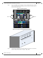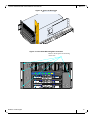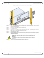
1
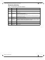
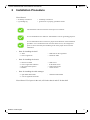
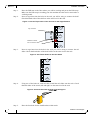
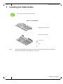
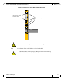
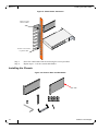
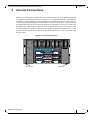
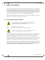
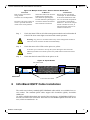
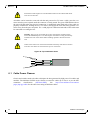
108 Port InfiniBand QDR Switch Platform
Installation Guide
PN: MIS5100Q-3DNC
Rev 1.4
www.mellanox.com
Rev 1.4
NOTE:
THIS HARDWARE, SOFTWARE OR TEST SUITE PRODUCT (“PRODUCT(S)”) AND ITS RELATED
DOCUMENTATION ARE PROVIDED BY MELLANOX TECHNOLOGIES “AS-IS” WITH ALL FAULTS OF ANY
KIND AND SOLELY FOR THE PURPOSE OF AIDING THE CUSTOMER IN TESTING APPLICATIONS THAT USE
THE PRODUCTS IN DESIGNATED SOLUTIONS. THE CUSTOMER'S MANUFACTURING TEST ENVIRONMENT
HAS NOT MET THE STANDARDS SET BY MELLANOX TECHNOLOGIES TO FULLY QUALIFY THE
PRODUCTO(S) AND/OR THE SYSTEM USING IT. THEREFORE, MELLANOX TECHNOLOGIES CANNOT AND
DOES NOT GUARANTEE OR WARRANT THAT THE PRODUCTS WILL OPERATE WITH THE HIGHEST QUALITY.
ANY EXPRESS OR IMPLIED WARRANTIES, INCLUDING, BUT NOT LIMITED TO, THE IMPLIED WARRANTIES
OF MERCHANTABILITY, FITNESS FOR A PARTICULAR PURPOSE AND NONINFRINGEMENT ARE
DISCLAIMED. IN NO EVENT SHALL MELLANOX BE LIABLE TO CUSTOMER OR ANY THIRD PARTIES FOR
ANY DIRECT, INDIRECT, SPECIAL, EXEMPLARY, OR CONSEQUENTIAL DAMAGES OF ANY KIND (INCLUDING,
BUT NOT LIMITED TO, PAYMENT FOR PROCUREMENT OF SUBSTITUTE GOODS OR SERVICES; LOSS OF USE,
DATA, OR PROFITS; OR BUSINESS INTERRUPTION) HOWEVER CAUSED AND ON ANY THEORY OF LIABILITY,
WHETHER IN CONTRACT, STRICT LIABILITY, OR TORT (INCLUDING NEGLIGENCE OR OTHERWISE) ARISING
IN ANY WAY FROM THE USE OF THE PRODUCT(S) AND RELATED DOCUMENTATION EVEN IF ADVISED OF
THE POSSIBILITY OF SUCH DAMAGE.
Mellanox Technologies
350 Oakmead Parkway Suite 100
Sunnyvale, CA 94085
U.S.A.
www.mellanox.com
Tel: (408) 970-3400
Fax: (408) 970-3403
Mellanox Technologies, Ltd.
PO Box 586 Hermon Building
Yokneam 20692
Israel
Tel: +972-4-909-7200
Fax: +972-4-959-3245
© Copyright 2010. Mellanox Technologies. All rights reserved.
Mellanox, BridgeX, ConnectX, Virtual Protocol Interconnect, PhyX, InfiniBlast, InfiniBridge, InfiniHost, InfiniRISC,
InfiniScale, and InfiniPCI are registered trademarks of Mellanox Technologies, Ltd. CORE-Direct, and FabricIT are
trademarks of Mellanox Technologies, Ltd. All other trademarks are property of their respective owners.
All other marks and names mentioned herein may be trademarks of their respective companies.
108 Port InfiniBand QDR Switch Platform Installation Guide
2
Mellanox Technologies
Document Number: 3261
108 Port InfiniBand QDR Switch Platform User Manual
Rev 1.4
Table of Contents
Chapter 1
Chassis Installation . . . . . . . . . . . . . . . . . . . . . . . . . . . . . . . . . . . . . . . . . . . . . . . . . . . . . 8
1.1
1.2
1.3
1.4
Chapter 2
Chassis Package Contents . . . . . . . . . . . . . . . . . . . . . . . . . . . . . . . . . . . . . . . . . . . . . . . . . . . . . . . . . . . .
Physical Installation . . . . . . . . . . . . . . . . . . . . . . . . . . . . . . . . . . . . . . . . . . . . . . . . . . . . . . . . . . . . . . . . .
Starting with the Rack . . . . . . . . . . . . . . . . . . . . . . . . . . . . . . . . . . . . . . . . . . . . . . . . . . . . . . . . . . . . . . .
1.3.1 Rack Recommendations . . . . . . . . . . . . . . . . . . . . . . . . . . . . . . . . . . . . . . . . . . . . . . . . . . . . .
1.3.2 ESD Connection . . . . . . . . . . . . . . . . . . . . . . . . . . . . . . . . . . . . . . . . . . . . . . . . . . . . . . . . . . .
Air Flow . . . . . . . . . . . . . . . . . . . . . . . . . . . . . . . . . . . . . . . . . . . . . . . . . . . . . . . . . . . . . . . . . . . . . . . . . .
8
9
9
9
9
9
Installation Procedure. . . . . . . . . . . . . . . . . . . . . . . . . . . . . . . . . . . . . . . . . . . . . . . . . . 10
2.1
2.2
Opening the Container . . . . . . . . . . . . . . . . . . . . . . . . . . . . . . . . . . . . . . . . . . . . . . . . . . . . . . . . . . . . . . 12
Installing the Bottom Shelf . . . . . . . . . . . . . . . . . . . . . . . . . . . . . . . . . . . . . . . . . . . . . . . . . . . . . . . . . . 12
Chapter 3
Installing the Cable Holder. . . . . . . . . . . . . . . . . . . . . . . . . . . . . . . . . . . . . . . . . . . . . . 15
Chapter 4
Ground Connections . . . . . . . . . . . . . . . . . . . . . . . . . . . . . . . . . . . . . . . . . . . . . . . . . . . 22
Chapter 5
Power Connections . . . . . . . . . . . . . . . . . . . . . . . . . . . . . . . . . . . . . . . . . . . . . . . . . . . . 23
5.1
Chapter 6
InfiniBand QSFP Cable Installation . . . . . . . . . . . . . . . . . . . . . . . . . . . . . . . . . . . . . . 24
6.1
Chapter 7
Configuring the Switch Management Modules for the First Time . . . . . . . . . . . . . . . . . . . . . . . . . . . . 28
Fabric Management Software . . . . . . . . . . . . . . . . . . . . . . . . . . . . . . . . . . . . . . . . . . . 34
9.1
9.2
9.3
9.4
9.5
9.6
Chapter 10
Power Supply and Spine Board Indicator Status at Power ON . . . . . . . . . . . . . . . . . . . . . . . . . . . . . . . 26
InfiniBand Fabric Initialization and Management . . . . . . . . . . . . . . . . . . . . . . . . . . 27
8.1
Chapter 9
Cable Power Classes . . . . . . . . . . . . . . . . . . . . . . . . . . . . . . . . . . . . . . . . . . . . . . . . . . . . . . . . . . . . . . . 25
Chassis Power Up . . . . . . . . . . . . . . . . . . . . . . . . . . . . . . . . . . . . . . . . . . . . . . . . . . . . . 26
7.1
Chapter 8
Powering Up the Switch Platform . . . . . . . . . . . . . . . . . . . . . . . . . . . . . . . . . . . . . . . . . . . . . . . . . . . . . 23
Downloading FabricIT Software and Documents . . . . . . . . . . . . . . . . . . . . . . . . . . . . . . . . . . . . . . . . .
Installing Licenses . . . . . . . . . . . . . . . . . . . . . . . . . . . . . . . . . . . . . . . . . . . . . . . . . . . . . . . . . . . . . . . . .
Getting and Inserting the License Key . . . . . . . . . . . . . . . . . . . . . . . . . . . . . . . . . . . . . . . . . . . . . . . . .
FabricIT Management and Inspection License . . . . . . . . . . . . . . . . . . . . . . . . . . . . . . . . . . . . . . . . . . .
Starting an SSH Connection to the Switch . . . . . . . . . . . . . . . . . . . . . . . . . . . . . . . . . . . . . . . . . . . . . .
Starting a WebUI Connection to the Switch . . . . . . . . . . . . . . . . . . . . . . . . . . . . . . . . . . . . . . . . . . . . .
34
35
35
38
38
38
Resetting the Switch . . . . . . . . . . . . . . . . . . . . . . . . . . . . . . . . . . . . . . . . . . . . . . . . . . 39
Mellanox Technologies
1
108 Port InfiniBand QDR Switch Platform User Manual
Rev 1.4
List of Figures
Figure 1:
Shelf Installation Kit Parts . . . . . . . . . . . . . . . . . . . . . . . . . . . . . . . . . . . . . . . . . . . . . . . . 11
Figure 2:
Chassis Installation Parts . . . . . . . . . . . . . . . . . . . . . . . . . . . . . . . . . . . . . . . . . . . . . . . . . 11
Figure 3:
Use the Top 2 Holes of the U Level for the Angle Bracket . . . . . . . . . . . . . . . . . . . . . . . 13
Figure 4:
Use These Holes for the Rail Slides . . . . . . . . . . . . . . . . . . . . . . . . . . . . . . . . . . . . . . . . . 13
Figure 5:
Connect Rail Slide to Rack Vertical Support . . . . . . . . . . . . . . . . . . . . . . . . . . . . . . . . . . 13
Figure 6:
Inserting the Caged Nuts for the Faceplate . . . . . . . . . . . . . . . . . . . . . . . . . . . . . . . . . . . 14
Figure 7:
Cable Holders . . . . . . . . . . . . . . . . . . . . . . . . . . . . . . . . . . . . . . . . . . . . . . . . . . . . . . . . . . 15
Figure 8:
Inserting the Caged Nuts for the Cable Holder. . . . . . . . . . . . . . . . . . . . . . . . . . . . . . . . . 16
Figure 9:
Cable Holder Placement . . . . . . . . . . . . . . . . . . . . . . . . . . . . . . . . . . . . . . . . . . . . . . . . . . 17
Figure 10: Chassis Rails and Rail Slides . . . . . . . . . . . . . . . . . . . . . . . . . . . . . . . . . . . . . . . . . . . . . . 17
Figure 11: Handle Locations . . . . . . . . . . . . . . . . . . . . . . . . . . . . . . . . . . . . . . . . . . . . . . . . . . . . . . . 18
Figure 12: The Rails are Preinstalled Onto the Chassis . . . . . . . . . . . . . . . . . . . . . . . . . . . . . . . . . . . 18
Figure 13: Rail Slide on . . . . . . . . . . . . . . . . . . . . . . . . . . . . . . . . . . . . . . . . . . . . . . . . . . . . . . . . . . . 19
Figure 14: Place the Rail Slide . . . . . . . . . . . . . . . . . . . . . . . . . . . . . . . . . . . . . . . . . . . . . . . . . . . . . . 20
Figure 15: Face Plate Mounting Bolt Locations. . . . . . . . . . . . . . . . . . . . . . . . . . . . . . . . . . . . . . . . . 20
Figure 16: Move the Rail Slide to the Vertical Support . . . . . . . . . . . . . . . . . . . . . . . . . . . . . . . . . . . 21
Figure 17: Ground Connection . . . . . . . . . . . . . . . . . . . . . . . . . . . . . . . . . . . . . . . . . . . . . . . . . . . . . 22
Figure 18: Multiple Power Inlets - Electric Caution Notification . . . . . . . . . . . . . . . . . . . . . . . . . . . 24
Figure 19: Spine Module . . . . . . . . . . . . . . . . . . . . . . . . . . . . . . . . . . . . . . . . . . . . . . . . . . . . . . . . . . 24
Figure 20: Top and Bottom Ports . . . . . . . . . . . . . . . . . . . . . . . . . . . . . . . . . . . . . . . . . . . . . . . . . . . . 25
Figure 21: Connecting the Harness to the Console . . . . . . . . . . . . . . . . . . . . . . . . . . . . . . . . . . . . . . 28
Figure 22: License Key Entitlement Number. . . . . . . . . . . . . . . . . . . . . . . . . . . . . . . . . . . . . . . . . . . 35
Figure 23: License Key Generation Form . . . . . . . . . . . . . . . . . . . . . . . . . . . . . . . . . . . . . . . . . . . . . 36
Figure 24: FabricIT Status/Licensing . . . . . . . . . . . . . . . . . . . . . . . . . . . . . . . . . . . . . . . . . . . . . . . . . 37
Figure 25: Web UI Login Page. . . . . . . . . . . . . . . . . . . . . . . . . . . . . . . . . . . . . . . . . . . . . . . . . . . . . . 39
Figure 26: Reset Button . . . . . . . . . . . . . . . . . . . . . . . . . . . . . . . . . . . . . . . . . . . . . . . . . . . . . . . . . . . 39
Mellanox Technologies
1
108 Port InfiniBand QDR Switch Platform User Manual
Rev 1.4
List of Tables
Table 1:
Revision History of this User’s Manual . . . . . . . . . . . . . . . . . . . . . . . . . . . . . . . . . . . . . . . 6
Table 2:
Reference Documents and Web Sites . . . . . . . . . . . . . . . . . . . . . . . . . . . . . . . . . . . . . . . . . 7
Table 3:
LEDs Display for Normal Operation . . . . . . . . . . . . . . . . . . . . . . . . . . . . . . . . . . . . . . . . 27
Table 4:
Serial Terminal Program Configuration . . . . . . . . . . . . . . . . . . . . . . . . . . . . . . . . . . . . . . 28
Table 5:
Configuration Wizard Session - IP Configuration by DHCP . . . . . . . . . . . . . . . . . . . . . . 29
Table 6:
Configuration Wizard Session - IP Zeroconf Configuration . . . . . . . . . . . . . . . . . . . . . . 31
Table 7:
Configuration Wizard Session - Static IP Configuration . . . . . . . . . . . . . . . . . . . . . . . . . 32
Mellanox Technologies
1
108 Port InfiniBand QDR Switch Platform User Manual
Rev 1.4
Revision History
Table 1 - Revision History of this User’s Manual
Revision
Date
Details
1.4
Oct. 2010
Added air flow direction
1.3
Oct. 2010
Removed the Chassis Rail from the installtion kit and from the installation
instructions.
1.2
Aug. 2010
Added weight lifing warning
Added step to Installation procedure
“Remove all protective plastic film from all sides and top of the chassis.”
Added cable power classes
1.1.3
July 2010
Added last page with barcode
1.1.2
July 2010
Added Note regarding initial configuration of the master and slave MMs
Added note regarding configuring the Box IP (BIP)
1.1.1
June 2010
minor fixes
1.1
June 2010
Added book files
1.0
May 2010
Initial release
Mellanox Technologies
1
Rev 1.4
About this Manual
This manual provides installation and set-up instructions for the IS5100 GT series QSFP Chassis
InfiniBand Switch Platform.
Intended Audience
This manual is intended for users and system administrators responsible for installing and setting
up the switch platform.
The manual assumes familiarity with the InfiniBand® architecture specification.
Related Documentation
The documentation set accompanying the QSFP Chassis InfiniBand Switch platform includes the
following:
Table 2 - Reference Documents and Web Sites
Switch Firmware and Firmware Update Tools See
http://www.mellanox.com/content/
pages.php?pg=management_tools&menu_section=34
Note that the Switch System described in this manual is
based on Mellanox Technologies’ InfiniScale® IV switch
device.
FabricIT TM Enterprise Fabric Management
(EFM) Software User’s Manual
Talk to your Mellanox representative for information
regarding licensing and implementation of the FabricIT
Enterprise Fabric Management Software System.
See
This symbol indicates a recommendation.
Document Conventions
When discussing memory sizes, MB and MBytes are used in this document to mean size in mega
bytes. The use of Mb or Mbits (small b) indicates size in mega bits.
This symbol indicates a recommendation.
2
Mellanox Technologies
108 Port InfiniBand QDR Switch Platform User Manual
1
Rev 1.4
Chassis Installation
Installation and initialization of the chassis is a simple process requiring attention to the
normal mechanical, power, and thermal precautions for rack-mounted equipment. Your
Chassis will be shipped in two packages one with the all of the leafs (leaf package) that are
ordered and an extra management module should it be ordered, and the second package
(chassis package) with all of the rest of the parts.
The chassis requires initial configuration to get the chassis and Fabric management up and
running through remote management. See the Installation Guide that is packed in the box
for the instructions to make the initial configuration.
This unit is intended for installation in a Restricted Access Location. A
restricted access area can be accessed only through the use of a special tool, lock
and key, or other means of security.
1.1 Chassis Package Contents
The package includes:
• 1 chassis in the basic configuration (3 spines, 0 leafs, 1 management module, 4 fans, 3
PSUs)
• 1 installation kit
• 1 box containing 3 power cords 125V 10A, C14 to C13, 6 feet long, USA UL Standard
and
1 RJ45 to DB9 harness
• 1 cable management kit
• 1 installation guide (this document)
• 1 parts list
Before you install your new IS5100 series chassis, unpack the system and check to make
sure that all the parts have been sent. Check the parts against the parts list. Check the parts
for visible damages that may have occurred during shipping.
If anything is damaged or missing, contact your customer representative immediately.
The rack mounting holes conform to the IEA-310 standard for 19-inch racks.
Guarantee proper ventilation, by leaving 8cm (3”) of space to the front and rear
of the switch. This will ensure proper air flow through the chassis. This is crucial for maintaining good airflow at ambient temperature. In particular, route
cables such that they do not impede the air into or out of the chassis.
Mellanox Technologies
1
Rev 1.4
Chassis Installation
1.2 Physical Installation
This equipment is very heavy. Safety is the first concern. The fully loaded chassis weighs~170 lbs (77 kg). Make sure that proper manpower and equipment is
used for transporting and moving the chassis.
The switch platform uses 7Uof rack space in a standard 19” rack, 6U for the chassis and 1U for the
shelf. The switch ships from the factory with mounting holes on the spine side. There are upper
brackets to connect the leaf side to the rack near the top of the chassis. The weight of the switch is
supported from underneath the unit by the shelf.
This chassis can be installed in 19” racks with a minimum depth of 80 cm. This depth is the minimum necessary to allow enough room for cable placement, without affecting ventilation through
the chassis.
Choose a rack which is able to support the mechanical and environmental characteristics of a fully
populated switch chassis.
1.3 Starting with the Rack
1.3.1 Rack Recommendations
Mellanox recommends a rack that is at least 80 cm long.
1.3.2 ESD Connection
Before starting any procedure on the IS5100 series switch system:
Step 1.
Step 2.
1.4
Put an ESD prevention wrist strap on your wrist, and make sure there is good contact
between your body and the strap.
Plug the other end of the wrist strap to a valid ground. Make sure that this is a tight fit.
Air Flow
These switches come with the air flow pattern of air entering through the spine side and exiting
through the connector side.
2
Mellanox Technologies
108 Port InfiniBand QDR Switch Platform User Manual
2
Rev 1.4
Installation Procedure
You will need:
• #2 Phillips screwdriver
• a grounding lug
• #3 Phillips screwdriver
• ground wire to properly ground the chassis
The installation will be much easier with a power screwdriver.
It is recommended to use AWG6 or 4mm diameter wire for grounding purposes.
It is recommended to have at least two people for the duration of the installation
procedure. Use a mechanical lift to raise this chassis. If not, use enough manpower to ensure the safety and wellbeing of all of the people involved in the
installation.
•
Parts for installing the shelf
- 1 shelf
- 4 sets of caged nuts
•
Parts for installing the chassis
-
•
- 4 M6 bolts for the caged nuts
- 2 shelf rail slides
2 chassis rail slides
8 sets of caged nuts and bolts
2 flat 4 hole metal spacers
4 handles
-
8 M4 screws
12 flat head screws
8 Allen head screws
1 Allen wrench
Parts for installing the cable manager
- 1 right hand cable holder
- 8 sets of caged nuts and bolts
- 1 left hand cable holder
You will need 7U of space in the rack, 6U for the chassis and 1U for the shelf.
Mellanox Technologies
3
Rev 1.4
Installation Procedure
Figure 1: Shelf Installation Kit Parts
Shelf
Angled
bracket
Rail
Rail slide
Caged nut
x8
M6 bolt
x8
Figure 2: Chassis Installation Parts
Rail slide
L
R
2 washers
8 M6 pan head
screws
1 Allen
wrench
12 flat head
screws
8 Allen head screws
for the handles
4 handles
4
Mellanox Technologies
108 Port InfiniBand QDR Switch Platform User Manual
Rev 1.4
2.1 Opening the Container
Step 1.
Step 2.
Before starting the procedure, put the ESD strap on and connect it to a valid
ground.
Remove all four sides of the container. Open the crate by opening the latches.
t
Danger of Bodily Injury Due to Weight, use enough people to safely lift this
product.
<40 lbs
<18 kgs
Step
Step
Step
Step
3.
4.
5.
6.
Step 7.
Step 8.
40 - 70 lbs
18 - 32 kgs
70 - 121 lbs
32 - 55 kgs
>121 lbs
>55 kgs
Remove and put aside the box containing the cables.
Remove and put aside the box containing the cable management kit.
Remove and put aside the box containing the Installation kit.
Visually inspect the chassis. Make sure that:
• there is no visible damage
• all 3 spines are installed
• all 3 PSUs are installed
• all 4 fans are installed
• 1 management module is installed
Remove all protective plastic film from all sides and top of the chassis.
Remove all of the spines, power supply units, fan units, and management
modules, and put aside for reinstallation after the chassis is installed in the
rack in order to make the weight more manageable. If you are using a
mechanical lift you can skip this step.
The leafs are shipped separately.
2.2 Installing the Bottom Shelf
The side of the chassis with the spine units will sit flush with the vertical supports of the rack. The side of the chassis with the QSFP connectors will sit at the
edge of the shelf closer to the center of the rack.
Step 9.
Mellanox Technologies
5
Rev 1.4
Installation Procedure
Step 1.
Step 2.
Place the ESD mat on the floor where you will be working and put on the ESD strap.
Make sure the ESD strap is touching your skin and that the other end is connected to a
verified ground.
Insert 4 caged nuts into the holes in the rack you will be using to connect the shelf.
Check that both sides of the shelf are at the same level in the rack.
Figure 3: Use the Top 2 Holes of the U Level for the Angle Bracket
21
Top of shelf
20
Bottom of shelf
Do not use this hole
19
Step 3.
Insert 4 caged nuts into the holes in the rack you will be using to connect the rail
slides. Check that both sides of the shelf will be at the same level in the rack.
Figure 4: Use These Holes for the Rail Slides
21
20
19
Step 4.
Using two of the bolts for each rail slide, install the rail slides onto the rack. Check
that both sides of the switch, left and right, are the same level in the rack.
Figure 5: Connect Rail Slide to Rack Vertical Support
Step 5.
6
Place the four bolts for the shelf brackets within reach.
Mellanox Technologies
108 Port InfiniBand QDR Switch Platform User Manual
Step
Step
Step
Step
6.
7.
8.
9.
Rev 1.4
Slide the shelf into the rail slides.
Put the shelf into place and screw the bolts into the nuts from step 2.
Tighten all of the screws to 9.2 Nm or 81.5 pound inches.
Insert 8 caged nuts for the faceplate in the exact locations shown in
Figure 6,“Inserting the Caged Nuts for the Faceplate”.
Figure 6: Inserting the Caged Nuts for the Faceplate
6
5
4
Place the caged nuts here.
3
2
1
Shelf
Mellanox Technologies
7
Rev 1.4
3
Installing the Cable Holder
Installing the Cable Holder
Now is the time to install the cable holder.
Figure 7: Cable Holders
Right hand Cable holder
Left hand Cable holder
Caged nut
Bolt
Step 1.
8
Place the Cable holder next to the rack, on the connector side of the chassis, and identify the holes where the caged nuts are to be placed.
Mellanox Technologies
108 Port InfiniBand QDR Switch Platform User Manual
Rev 1.4
Figure 8: Inserting the Caged Nuts for the Cable Holder
5
Place for the upper
bracket washer
4
Place the cageds nuts here
3
2
1
Shelf
The cable holders should go to the outside of the vertical supports.
Step 2.
Set the bottom of the cable holder at the level of the shelf.
If the cable holder is not set properly the upper bracket will not line up
with the cable holder.
Mellanox Technologies
9
Rev 1.4
Installing the Cable Holder
Figure 9: Cable Holder Placement
Notch for upper
bracket washer
L
Set this even with the
top of the shelf
Step 3.
Step 4.
Screw the cable holder onto the rack using the screws provided.
Repeat steps 1- 3 for the second cable holder.
Installing the Chassis
Figure 10: Chassis Rails and Rail Slides
Rail slide
L
10
R
Mellanox Technologies
108 Port InfiniBand QDR Switch Platform User Manual
Step 1.
Rev 1.4
Screw the handles onto the chassis. Use the 8 Allen head screws, and the
Allen wrench provided. Two handles go on the connector side and two go on
the power side of the chassis.
Figure 11: Handle Locations
PS1
IS5100
S1
FAN
S2
FAN
PS3
PS2
Handles
Handles
S3
FAN
AC2
AC1
AC3
I2C
CONSOLE
MGT
RST
PSU
S.Fans
L.Fans
Master
I2C
CONSOLE
MGT
RST
PSU
S.Fans
L.Fans
Master
Figure 12: The Rails are Preinstalled Onto the Chassis
R
Step 2.
Mellanox Technologies
Lift the chassis and slide it onto the shelf. Make sure that there are at least four
people to safely lift this chassis. It weighs ~ 45kg / 99lbs.
11
Rev 1.4
Installing the Cable Holder
Step 3.
Step 4.
Push the chassis into the rack until the faceplate is ~ 20cm (~ 8”) from the vertical
support.
Put the rail slides onto the rails.
Figure 13: Rail Slide on
R
R
Step 5.
Step 6.
Step 7.
Step 8.
Step 9.
12
Slide the chassis further into the rack.
Place the caged nuts in the rack in the places corresponding to their places in the faceplate.
Slide the chassis all the way into the rack until the faceplate is touching the vertical
rack support. The caged nuts placed in the last procedure should line up with the holes
in the faceplate.
Screw the 8 screws through the faceplate and into the caged nuts.
Slide the rail slides to the vertical rails.
Mellanox Technologies
108 Port InfiniBand QDR Switch Platform User Manual
Rev 1.4
Figure 14: Place the Rail Slide
R
Figure 15: Face Plate Mounting Bolt Locations
Holes in the faceplate for mounting
on the rack.
PS1
IS5100
S1
S2
FAN
FAN
PS2
S3
Mellanox Technologies
PS3
FAN
13
Rev 1.4
Installing the Cable Holder
Figure 16: Move the Rail Slide to the Vertical Support
R
Step 10.
Step 11.
Step 12.
Step 13.
Step 14.
Step 15.
Place the 4 holed spacer on the outside of the vertical support and screw in the 4
screws for each rail slide.
Remove all four handles and save forfuture use.
Ground the switch.
Repace all of the spines, power supply units, fan units, and management modules
removed at the start of the installation procedure.
Plug in the power cables.
Check the Status LEDs and confirm that all of the LEDs show status lights consistent
with normal operation.
Warning: Any yellow status LED is cause for concern and must be dealt with
immediately.
It can take up to 3 minutes to boot up, during which time the status LED may
indicate red.
Step 16.
14
You can start connecting all of the cables to the switch.
Mellanox Technologies
108 Port InfiniBand QDR Switch Platform User Manual
4
Rev 1.4
Ground Connections
Make sure to connect the ground post to a valid electrical ground. Use a grounding lug and
a ground wire of sufficient capacity to safely convey a potential discharge. A ground wire
of AWG 6 or 4mm diameter is recommended for grounding this device. The chassis is
concurrently grounded through each of the PSUs. Only connect the PSU cords to properly
grounded outlets. Do not rely on the PSU grounds. It is absolutely necessary to connect the
grounding post. Make sure the connections are solid and permanent. If you choose to not
use the ground screw, make sure that the rack is properly grounded and that there is a valid
ground connection between the chassis of the switch and the rack. Test the ground using
an Ohm meter.
Figure 17: Ground Connection
PS1
IS5100
S1
S2
FAN
FAN
PS2
S3
Ground Post
Mellanox Technologies
PS3
FAN
ESD Post
15
Rev 1.4
5
Power Connections
Power Connections
The chassis includes integrated hot-swap power supplies which support up to 3 load-sharing
1000W supply units. The slots for the power supply units (PSUs) are on the spine side. The left
side has odd numbered PSUs and the right side has even numbered PSUs. Each PSU has a dedicated AC inlet. This design enables the optional use of separate main and backup AC feeds. The
input voltage is Autorange, 100-240 VAC, 50Hz or 60Hz. The output voltage for the PSUs is 48V.
The power cords are standard 3-wire AC power cords including a safety ground.
Before starting any procedure on the IS5100 series switch system put an ESD prevention wrist
strap on your wrist and connect to the IS5100 series chassis.
5.1 Powering Up the Switch Platform
Make sure that the power cords are compatible with your outlets. Power cords
for different countries can be ordered from Mellanox. See the user manual
appendix for ordering part numbers for power cords.
Step 1.
Step 2.
Plug in the power cords to the PSUs.
Plug the other end of the power cord into a grounded outlets.
Make sure that the outlets and circuits will not be overloaded. Spread out the
load over at least two or three circuits or use a 3 phase circuit.
The Chassis must be started a full compliment of possible PSUs, thereafter it can run on one less
than the total number of PSUs. This final PSU is redundant and allows for hot swapping a PSU
should one fail. Connecting the PSUs to different AC lines provides AC failover protection.
A system should continue to run and allow a hotswap of a defective PSU. Should there not be
enough power to keep all of the leafs running, FabricIT EFM may power down some leafs. If this
happens it may be necessary to reboot the chassis once the defective PSU has been replaced.
The power system will divide the current consumption by the number of working PSUs. Should
one of the PSUs fail, the total current consumption will then be divided by the remaining working
PSUs. When the failed PSU is hot swapped the new PSU will ramp up and pass its share of current, so that the total current is always divided by the number of working PSUs.
16
Mellanox Technologies
108 Port InfiniBand QDR Switch Platform User Manual
Rev 1.4
Figure 18: Multiple Power Inlets - Electric Caution Notification
CAUTION
Risk of electric shock and
energy hazard.
The PSUs are all independent.
ACHTUNG
Gafahr des elektrischen Schocks.
Entferrnen des Netzsteckers
elnes Netzteils spannungsfrei.
Um alle Einhieten spannungsfrei
Disconnect all power supplies to zu machen sind die Netzstecker
ensure a powered down state
aller Netzteile zu entfernen
inside of the switch platform.
Step 3.
ATTENTION
Risque de choc et de danger
e’lectriques. Le de’branchment
d’une seule alimentation stabilise’e ne de’branch uniquement
qu’un module “Alimentation
Stabilise’e”. Pour isoler completement le module en cause, Il
faut de’brancher toutes les alimentations stabilise’es.
Check the Status LEDs on all of the management modules and confirm that all
of the LEDs show status lights consistent with normal operation.
Warning: Any yellow or red status LEDs on any of the management modules is
cause for concern and must be dealt with immediately.
Step 4.
Check that none of the LEDs on the spines are yellow.
It can take up to 3 minutes to boot up the system. during this time the status
LEDs may be RED. Turn off the system if any LEDs remain red for more than 3
minutes.
Step 5.
Check that the leaf status LEDs in the spines are lit.
Figure 19: Spine Module
Fan status LEDs
Status
1 3 5
7 9 11 13 15 17
19 21 23 25 27 29 31 33 35
Fan Status
2 4 6 8 10 12 14 16 18
20 22 24 26 28 30 32 34 36
Status LED
Leaf connection LEDs
6
InfiniBand QSFP Cable Installation
The switch uses industry standard QSFP InfiniBand cables which are available from several vendors. The standard QSFP cables support full 40+40Gb/s (QDR), 20+20Gb/s
(DDR) and
10+10Gb/s (SDR) bidirectional wire speed of the switch ports. All InfiniBand QSFP connections are made to the leaf boards. Each leaf has 18 InfiniBand QSFP connectors in two
rows, which are numbered 1-18.
Mellanox Technologies
17
Rev 1.4
InfiniBand QSFP Cable Installation
If maximum cable lengths are exceeded data transfer will be reduced and the bit
error rate will increase.
All cables can be inserted or removed with the unit powered on. To insert a cable, press the connector onto the port receptacle until the connector is firmly seated. The green LED indicator above
the port will light when the physical connection is established (when both ends of the cable are
properly connected to working devices). To remove, disengage the lock and slowly pull the connector away from the port receptacle. For a valid physical connection both ends of the cable must
be connected to working devices.
Warning: Take care to not impede the air flow through the ventilation holes
next to the InfiniBand ports. Use cable lengths which allow routing horizontally
around to the side of the chassis before bending upward or downward in the
rack.
Cables in the bottom row of the leafs should be inserted up side down in relation
to the how the cables are inserted in the top row of the leafs.
Figure 20: Top and Bottom Ports
6.1 Cable Power Classes
Chassis and switches need to be able to dissipate the heat generated by high power I/O cables and
modules. The Mellanox IS5X00 series chassis are rated for cables up to class 2 as per the SFF
committee
classification
(SFF-8436.PDF).
See
http://www.mellanox.com/content/
pages.php?pg=cables for the cable class rating of Mellanox cables.
18
Mellanox Technologies
108 Port InfiniBand QDR Switch Platform User Manual
7
Rev 1.4
Chassis Power Up
Before starting any procedure on the IS5100 series switch system put an ESD prevention
wrist strap on your wrist and connect to the IS5100 series chassis.
The Chassis must be started with a full complement of PSUs, that is 3. Thereafter it can
run on one less than the total number of PSUs. This final PSU is redundant and allows for
hot swapping a PSU should one fail. Connecting the PSUs to different AC lines provides
AC failover protection.
A system should continue to run and allow a hotswap of a defective PSU. Should there not
be enough power to keep all of the leafs running, FabricIT EFM may power down some
leafs. If this happens it may be necessary to reboot the chassis once the defective PSU has
been replaced.
Step 1.
Step
Step
Step
Step
Step
2.
3.
4.
5.
6.
Check all:
• boards
• power supplies
• leaf fan modules
• spine fan modules
for proper insertion and seating before connecting the AC power cords.
All leafs that you plan to use, insert in the chassis.
Insert thermal blanks in unused leaf slots to maintain balanced air flow.
Tighten all mounting screws.
Connect the power cords to the PSUs.
Connect the power cords to grounded electrical outlets.
Do not power up the chassis with less than all PSUs installed.
Populate the chassis with the leafs before you power up the chassis.
7.1 Power Supply and Spine Board Indicator Status at Power ON
It can take up to 3 minutes to boot up the system. during this time the status
LEDs may be RED. Turn off the system if any LEDs remain red for more than 3
minutes.
As the power is turned on, you should observe the following conditions for normal operation:
Mellanox Technologies
19
Rev 1.4
Chassis Power Up
Step 1.
Step 2.
Step 3.
Step 4.
Power Supply Unit(s) AC OK and DC OK indicators are ON and FAIL indicators are
OFF.
There is a green Status LED per spine board, per leaf board, and per management
module that indicates power supplies are good.
Spine Board indicators will display status of internal links to the installed leaf boards.
All PHY links to existing leaf Boards should be ON.
Check the management module LEDs and make sure they coincide with Table on
page 20.
Table 3 - LEDs Display for Normal Operation
20
Normal
State
LED
Description
STATUS
Off = No Power
Green = System is up and running.
Yellow = System warning. Attention needed (such as overheating).
Red = System not operational (Diagnostics fail, CPU hang,
HW fail, Overheat-critical)
Blinking Yellow = System booting / Restore factory defaults in
progress.
PSU STATUS
Green
Off = No power
Green = Normal operational
Red = PS fault detected. User should check individual power supplies for fault indications.
SPINE FANS
STATUS
Off = No power to fan
Green = Nominal operational
Yellow = Non fatal failure
Red = Fatal failure Turn the chassis off and then troubleshoot
Green
LEAF FANS
STATUS
Off = No power to fan
Green = Nominal operational
Yellow = Non fatal failure
Red = Fatal failure Turn the chassis off and then troubleshoot
Green
MGT1
STATUS
Off = no power or this management module is not installed
Green = Management module is operating as a master (i.e., the
other management module is a slave)
Yellow = Management module is operating as a slave (i.e., the
other management module is a master)
Green
MGT2
STATUS
Off = no power or this management module is not installed
Green = Management module is operating as a master (i.e., the
other management module is a slave)
Yellow = Management module is operating as a slave (i.e., the
other management module is a master)
Yellow
Green
Mellanox Technologies
108 Port InfiniBand QDR Switch Platform User Manual
8
Rev 1.4
InfiniBand Fabric Initialization and Management
Subnet Management and Subnet Administration are standard components defined by the
InfiniBand Specification which implement fabric initialization, discovery, and configuration.
The switch’s switching fabric can be managed by FabricIT, as well as any third
party Subnet Management software running on an InfiniBand Host that is connected to any switch port. The switch is also compatible with the Open Source
Subnet Manager OpenSM.
The switch is basically an InfiniBand fabric built out of individual InfiniBand switch
devices and appears so to external Subnet Managers. The switch supports the SystemImage GUID feature of the InfiniBand specification which means that software management
tools that support this feature can recognize all the internal devices as a single switch system.
8.1 Configuring the Switch Management Modules for the First Time
On IS5X00 systems, when having dual management systems, first connect the
cable and configure the master management module CPU and only then configure the slave. By default the master CPU is the top management module. For
further information on the master and slave roles, see the FabricIT Software UM
section “High Availability” for more information.
Initial configuration must be done on all of the management modules.
Step 1.
Connect the host PC RS232 connector to the CONSOLE port of the switch
using the supplied cable.
Figure 21: Connecting the Harness to the Console
Connect the host
PC to here
I2C
CONSOLE
MGT
RST
PSU
S.FANS L.FANS MASTER
No remote IP connection is available at this stage.
Mellanox Technologies
21
Rev 1.4
InfiniBand Fabric Initialization and Management
Step 2.
Configure a serial terminal program (for example, HyperTerminal, Minicom, or Tera
Term) on your host PC with the settings described in Table 4.
Table 4 - Serial Terminal Program Configuration
Parameter
Setting
Baud Rate
9600
Data bits
8
Stop bits
1
Parity
None
Flow Control
None
Step 3.
Step 4.
Login (from serial terminal program) as admin and use admin as password. This starts
the Mellanox configuration wizard.
Go through the Mellanox configuration wizard. Table 5 shows an example of a wizard
session.
Table 5 - Configuration Wizard Session - IP Configuration by DHCP (Sheet 1 of 2)
Wizard Session Display (Example)
Comments
Mellanox configuration wizard
Do you want to use the wizard for initial configuration? yes
You must perform this configuration the first time you
operate the switch or after resetting the switch to the
factory defaults. Type ‘y’ and then press <Enter>.
Step1: Hostname? [switch-1]
If you wish to accept the default hostname, then press
<Enter>. Otherwise, type a different hostname and
press <Enter>.
Step 2: Use DHCP on eth0 interface? [yes]
Perform this step to obtain an IP address for the switch.
(eth0 is the management port of the switch.)
If you wish the DHCP server to assign the IP address,
type ‘yes’ and press <Enter>.
If you type ‘no’ (no DHCP), then you will be asked
whether you wish to use the ‘zeroconf’ configuration
or not. If you enter ‘yes’ (yes Zeroconf), the session
will continue as shown in Table 6.
If you enter ‘no’ (no Zeroconf), then you need to enter
a static IP, and the session will continue as shown in
Table 7.
22
Mellanox Technologies
108 Port InfiniBand QDR Switch Platform User Manual
Rev 1.4
Table 5 - Configuration Wizard Session - IP Configuration by DHCP (Sheet 2 of 2)
Wizard Session Display (Example)
Step 3: Admin password (Press <Enter> to leave
unchanged)? <new_password>
Step 4: Confirm admin password? <new_password>
Comments
To avoid illegal access to the machine, please type a
password and then press <Enter>. Then confirm the
password by re-entering it.
Note that password characters are not printed.
You have entered the following information:
1. Hostname: <switch name>
2. Use DHCP on eth0 interface: yes
3. Admin password (Enter to leave unchanged):
(CHANGED)
To change an answer, enter the step number to return
to.
Otherwise hit <enter> to save changes and exit.
Choice: <Enter>
The wizard displays a summary of your choices and
then asks you to confirm the choices or to re-edit them.
Either press <Enter> to save changes and exit, or enter
the configuration step number that you wish to return
to.
Note:
To run the command “configuration jump-start” you
must be in Config mode.
Configuration changes saved.
To return to the wizard from the CLI, enter the “configuration jump-start” command from configuration
mode. Launching CLI...
<switch name> [>
Mellanox Technologies
23
Rev 1.4
InfiniBand Fabric Initialization and Management
Table 6 - Configuration Wizard Session - IP Zeroconf Configuration
Wizard Session Display - IP Zeroconf Configuration (Example)
Mellanox configuration wizard
Do you want to use the wizard for initial configuration? y
Step 1: Hostname? [switch-112126]
Step 2: Use DHCP on eth0 interface? [no]
Step 3: Use zeroconf on eth0 interface? [no] yes
Step 4: Default gateway? [192.168.10.1]
Step 5: Primary DNS server?
Step 6: Domain name?
Step 7: Admin password (Enter to leave unchanged)?
You have entered the following information:
1. Hostname: switch-112126
2. Use DHCP on eth0 interface: no
3. Use zeroconf on eth0 interface: yes
4. Default gateway: 192.168.10.1
5. Primary DNS server:
6. Domain name:
7. Admin password (Enter to leave unchanged): (unchanged)
To change an answer, enter the step number to return to.
Otherwise hit <enter> to save changes and exit.
Choice:
Configuration changes saved.
To return to the wizard from the CLI, enter the "configuration jump-start"
command from configure mode. Launching CLI...
switch-1 >
24
Mellanox Technologies
108 Port InfiniBand QDR Switch Platform User Manual
Rev 1.4
Table 7 - Configuration Wizard Session - Static IP Configuration
Wizard Session Display - Static IP Configuration (Example)
Mellanox configuration wizard
Do you want to use the wizard for initial configuration? y
Step 1: Hostname? [switch-112126]
Step 2: Use DHCP on eth0 interface? [yes] n
Step 3: Use zeroconf on eth0 interface? [no]
Step 4: Primary IP address? 192.168.10.4
Mask length may not be zero if address is not zero (interface eth0)
Step 5: Netmask? [0.0.0.0] 255.255.255.0
Step 6: Default gateway? 192.168.10.1
Step 7: Primary DNS server?
Step 8: Domain name?
Step 9: Admin password (Enter to leave unchanged)?
You have entered the following information:
1. Hostname: switch-112126
2. Use DHCP on eth0 interface: no
3. Use zeroconf on eth0 interface: no
4. Primary IP address: 192.168.10.4
5. Netmask: 255.255.255.0
6. Default gateway: 192.168.10.1
7. Primary DNS server:
8. Domain name:
9. Admin password (Enter to leave unchanged): (unchanged)
To change an answer, enter the step number to return to.
Otherwise hit <enter> to save changes and exit.
Choice:
Configuration changes saved.
To return to the wizard from the CLI, enter the "configuration jump-start"
command from configure mode. Launching CLI...
switch-1 >
switch-112428> enable
switch-112428# show interface eth0
// Enter ‘enable’ mode of CLI
// # indicates ‘enable’ mode
The following is an example of the output:
Interface eth0 state
Admin up:
yes
Link up:
yes
IP address:
192.168.10.6
Netmask:
255.255.255.0
Speed:
100Mb/s (auto)
Duplex:
full (auto)
Mellanox Technologies
25
Rev 1.4
InfiniBand Fabric Initialization and Management
Interface type:
ethernet
Interface source:
physical
MTU:
1500
HW address:
00:00:50:3A:8E:80
Comment:
RX bytes:
123102
RX packets:
1271
RX mcast packets:
0
RX discards:
0
RX errors:
0
RX overruns:
0
RX frame:
0
TX bytes:
122850
TX packets:
1119
TX discards:
0
TX errors:
0
TX overruns:
0
TX carrier:
0
TX collisions:
0
switch-112428#
Step 5.
Before attempting a remote (for example, SSH) connection to the switch, check the
eth0 interface configuration. Specifically, verify the existence of an IP address. To
check the current eth0 configuration, enter the following commands:
switch-1 > enable
switch-1
// Enter ‘enable’ mode of CLI
# show interface eth0
// # indicates ‘enable’ mode
The following is an example of the output:
Interface eth0 state
26
Admin up:
yes
Link up:
yes
IP address:
192.168.10.6
Netmask:
255.255.255.0
Speed:
100Mb/s (auto)
Duplex:
full (auto)
Interface type:
ethernet
Interface source:
physical
MTU:
1500
Mellanox Technologies
108 Port InfiniBand QDR Switch Platform User Manual
HW address:
Rev 1.4
00:00:50:3A:8E:80
Comment:
RX bytes:
123102
RX packets:
1271
RX mcast packets:
0
RX discards:
0
RX errors:
0
RX overruns:
0
RX frame:
0
TX bytes:
122850
TX packets:
1119
TX discards:
0
TX errors:
0
TX overruns:
0
TX carrier:
0
TX collisions:
0
switch-1
Step 6.
9
#
On IS5X00 systems, configure the Box IP (BIP) centralized location for chassis High Availability according to the steps in the FabricIT Software UM section “Box IP Centralized Location”.
Fabric Management Software
FabricIT EFM is a software based management system that can be run with either a command line interface or with a WebUI interface. Chassis management comes with the switch
system. An optional license is required for full use of FabricIT cluster management. See
the FabricIT EFM User Manual for instructions and commands available to manage the
chassis, switches, and fabric.
9.1 Downloading FabricIT Software and Documents
To download FabricIT software and documentation, please visit the following Web page:
http://www.mellanox.com/content/
pages.php?pg=ib_fabricit_efm_management&menu_section=55.
Note that you will need to enter the License Entitlement number and the Switch S/N to
obtain the software and documentation, and also to generate an EFM license that enables
extended FabricIT management and inspection features on your switch system.
Mellanox Technologies
27
Rev 1.4
Fabric Management Software
9.2 Installing Licenses
A license for extended FabricIT management and inspection features with FabricIT EFM software
is available for an additional licensing fee.
9.3 Getting and Inserting the License Key
FabricIT Enterprise Fabric Manager (EFM) license can be purchased from your Mellanox representative at any time. A License Entitlement Number will be supplied at the time of purchase. To
generate the License Key enter the License Entitlement Number and the Switch Serial Number
into the Mellanox online license tool at http://license.mellanox.com. The Switch Serial Number
can be found on the pull-out tab or the box labeling. For the serial number location on the chassis
see Section 1.1.1, “Serial Number and Product Version Information,” on page 10.
Step 1.
Step 2.
Go to http://license.mellanox.com.
Provide the Entitlement Number, provided on purchase of FabricIT Enterprise Fabric
Manager.
Figure 22: License Key Entitlement Number
Enter the provided Entitlement Number.
Step 3.
Step 4.
28
Generate the License Key.
Provide the purchased Switch Serial Number (Switch S/N).
Mellanox Technologies
108 Port InfiniBand QDR Switch Platform User Manual
Rev 1.4
Figure 23: License Key Generation Form
Enter the purchased Switch Serial Number and generate the License Key.
Step 5.
Step 6.
Mellanox Technologies
Print the generated license Key (PDF document is generated).
Go to the FabricIT page and click on Setup =>Licensing.
29
Rev 1.4
Fabric Management Software
Figure 24: FabricIT Status/Licensing
Step
Step
Step
Step
Step
Step
7.
8.
9.
10.
11.
12.
Input the generated License key.
Add New License (from FabricIT -> SETUP/Licensing link).
License Page shows active license(s) if available.
Enter this Key in the FabricIT GUI or using FabricIT CLI.
Click “Add Licenses”.
EFM is enabled.
On purchase of FabricIT EFM, every switch is shipped with an “Entitlement Certificate”.
License Key can be obtained using “CLI” or Web UI”.
Print up the certificate with all the information.
30
Mellanox Technologies
108 Port InfiniBand QDR Switch Platform User Manual
Rev 1.4
9.4 FabricIT Management and Inspection License
To activate extended FabricIT management and inspection features you need to install the
license that was purchased along with the switch system. Without the license, you will not
be able to run a Subnet Manager on the switch nor run advanced fabric diagnostics.
For information on installation, please refer to the FabricIT Enterprise Fabric Management Software CLI User’s Manual.
If FabricIT EFM is updated and the FW image in the leafs and spines of the chassis is
an earlier version than the minimum that the new version of EFM can work with, then
the Orca will require ~45 minutes to update all of the FW images in all of the leafs and
spines.
9.5 Starting an SSH Connection to the Switch
SSH connection also supports TelNet.
Step 1.
Step 2.
Step 3.
Set up an Ethernet connection between the switch and a local network
machine (“the remote machine” henceforth) using a standard RJ-45 connector.
Connect to the remote machine.
Start a remote shell to the switch using the following command:
ssh –l admin <your ip address>
When prompted for a password enter “admin”.
Note that the IP address used above is the same IP address that was assigned to the Mellanox
configuration wizard in the “Configuring the Switch Management Modules for the First Time”
section.
Step 4.
You can enter any supported command now.
For a complete reference of commands, please see Mellanox FabricIT Management Software User’s Manual.
9.6 Starting a WebUI Connection to the Switch
Step 1.
Step 2.
Mellanox Technologies
Set up an Ethernet connection between the switch and a local network
machine (“the remote machine” henceforth) using a standard RJ-45 connector.
Start a Web browse – Google Chrome, Internet Explorer 7.0 or Mozilla Firefox 3.0.
31
Rev 1.4
Resetting the Switch
Make sure the screen resolution is set to 1024*768 or higher.
Step 3.
Step 4.
Enter as URL the following: http://<switch_IP_address>
where <switch_IP_address> is the IP address of the switch or its DNS name.
You will receive the login window for remote management of the switch.
Figure 25: Web UI Login Page
Step 5.
Use admin for both the login (Account) and the password.
10 Resetting the Switch
On the connector side panel under the system LEDs is a reset button. This reset button requires a
tool to be pressed (a paper clip will do).
Figure 26: Reset Button
Use an opened paper clip to press the rest button.
CONSOLE
MGT
RST
PSU
S.FANS L.FAN
A quick push of this button resets the whole switch. When the button is held down for 5 seconds
the switch is reset and the password is reset to the factory default password. The LEDs will flicker
for a fraction of a second to indicate reset is occurring.
For more information and documentation on the IS5100 Series go to:
http://www.mellanox.com/content/pages.php?pg=products_dyn&product_family=71&menu_section=49
32
Mellanox Technologies
Rev 1.4
USA
Mellanox Technologies Inc.
350 Oakmead Parkway, Suite 100
Sunnyvale, CA 94085
Tel: (408) 970-3400
Fax: (408) 970-3403
www.mellanox.com
E-mail: [email protected]
Map and Directions
Tech Support: 408-916-0055
(8:00AM to 5:00 PM - Pacfic)
Mellanox Technologies, Ltd.
PO Box 586 Hermon Building
Yokneam, Israel 20692
Telephone: +972-4-909-7200
Fax: +972-4-959-3245
E-mail: [email protected]
Tech Support: +972 4 9097200 ext 250
(8:00AM to 5:00 PM - Israel Time)
www.mellanox.com
1
Mellanox Technologies
108Port InfiniBand QDR Switch Platform
Installation Guide