1
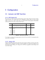
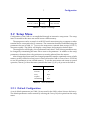
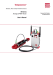
RAPID CONTROLS
SAB-A
USER
MANUAL
LDT to Analog Converter
Rapid Controls, Inc.
Rapid City, SD USA
www.rapidcontrols.com
[email protected]
tel: 605-348-7688
fax: 605-341-5496
December 21, 2011
© 2011 Rapid Controls Inc.
1
Contents
1 Introduction
1.1 Description
1.2 Features
1.3 Models and Ordering Information
2
2 Installation
2.1 Connections
4
3 Configuration
3.1 Jumpers and DIP Switches
3.2 Setup Menu
6
4 General Operation
4.1 Startup
4.2 Sensor Processing
4.3 Status
12
2
Introduction
1 Introduction
1.1 Description
The SAB-A converts two channels of magnetostrictive transducer position and velocity to two
or four analog voltage outputs. To achieve accurate, low-latency output, the conversion is
implemented using a micro-controller, EPLD, and 16-bit digital to analog converters.
The SAB-A continually interrogates the sensors for position data at a configurable rate.
Immediately after each position update, velocity data is calculated from the collected position
data. The analog outputs are then set based on the most recent data available.
Sensor update rate, velocity window size, and analog output scaling and offseting are configurable using a text-based menu accessible via an RS-232 serial port. Status LEDs provide
visual confirmation of proper sensor operation. A Sensor OK output for each channel allows
an external device to monitor sensor interface status.
Although the SAB-A was designed for use with magnetostrictive linear displacement transducers, it can be used with other types of sensors such as glass scales or encoders. To be used
with the SAB-A, a sensor must be compatible with the one of the sensor protocols supported
by the SAB-A: SSI, Start/Stop, or PWM.
1.2 Features
•
•
•
•
•
•
•
•
•
•
•
•
Two channels of position from Start/Stop, PWM or SSI magnetostrictive transducers
16-bit analog outputs (0.3 mV resolution) with selectable output voltage range
Voltage range options: -10 to 10V, 0 to 10V, -5 to 5V, 0 to 5V
Supports arbitrary SSI sensor resolution
56 MHz oscillator provides 0.002 inch resolution without reciculation for Start/Stop or
PWM sensors (Internal recirculations may be used to increase this)
Allows controlling all analog outputs from a single sensor with different scaling
Transducer OK output and LED signals valid transducer operation
Software selectable update rate, velocity window, and analog position/velocity scaling
and offsetting
Setup via RS-232 serial interface
Blinking LED indicates good operation of SAB-A
Watchdog timer for reset upon software failure
Non-volatile memory for storage of setup parameters
Introduction
3
•
•
Convenient screw terminal connections
4.64 × 5.31 × 1.77 (D×H×W) inch DIN rail mount enclosure
1.3 Models and Ordering Information
Table 1.1 shows the available SAB-A models. SAB-A units are available with 2 or 4 analog
outputs and with support for SSI or Start/Stop and PWM sensors.
Model Number
Channels
Sensor Interface
Position Output
Velocity Output
SAB-A-RPM-PA
2
Start/Stop & PWM
2× 16-bit
---
SAB-A-RPM-VA
2
Start/Stop & PWM
---
2× 16-bit
SAB-A-RPM-PA-VA
2
Start/Stop & PWM
2× 16-bit
2× 16-bit
SAB-A-SSI-PA
2
SSI
2× 16-bit
---
SAB-A-SSI-VA
2
SSI
---
2× 16-bit
SAB-A-SSI-PA-VA
2
SSI
2× 16-bit
2× 16-bit
Table 1.1
SAB-A Models and Ordering Information
4
Installation
2 Installation
2.1 Connections
The connectors of the SAB-A are shown in Figure 2.1. A diagram of thes connectors is shown
in Figure 2.2. Finally, Table 2.1] shows the pinout of the connectors.
Figure 2.1 SAB-A Connector Locations
Figure 2.2 SAB-A Connector Placement
Installation
5
Pin
Function
Pin
Function
J1-1
Logic Ground
J3-1
Ch A Clock+ to Sensor
J1-2
RS-232 RX from Host
J3-2
Ch A Clock− to Sensor
J1-3
RS-232 TX to Host
J3-3
Ch A Data+ from Sensor
J1-4
Reserved
J3-4
Ch A Data− from Sensor
J1-5
Reserved
J3-5
+24VDC Power to Sensor
J1-6
Input 1
J3-6
Ground
J1-7
Input 2
J3-7
No Connect
J1-8
Input Common
J3-8
Ch B Clock+ to Sensor
J1-9
Ch0 Sensor Status Output
J3-9
Ch B Clock− to Sensor
J1-10
Ch1 Sensor Status Output
J3-10
Ch B Data+ from Sensor
J3-11
Ch B Data− from Sensor
J4-1
+24 or +15VDC Power
J3-12
+24 or +15VDC Power to Sensor
J4-2
Power common and signal ground
J3-13
Ground
J4-3
-15VDC Power (Optional)
J3-14
-15VDC Power to Sensor (if needed)
Analog J1-1 (Pos)
Ch A Position Analog Out
Analog J1-1 (Vel)
Ch A Velocity Analog Out
Analog J1-2 (Pos)
Analog Ground
Analog J1-2 (Vel)
Analog Ground
Analog J1-3 (Pos)
Ch B Position Analog Out
Analog J1-3 (Vel)
Ch B Velocity Analog Out
Table 2.1
SAB-A Connector Pinouts
Configuration
6
3 Configuration
3.1 Jumpers and DIP Switches
3.1.1 DIP Switch S1
Dip switch S1 is used to select the desired analog output voltage range for all of the analog
output channels. The voltage range can be configured to operate with one of these output
ranges: -10 to 10 V, 0 to 10V, -5 to 5V, and 0 to 5V. The SAB-A’s analog outputs will maintain
16-bit resolution in any of the voltage output ranges.
Switch
Description
Switch Off
Switch On
Bipolar
Unipolar
10V
5V
S1-1
Analog voltage bipolar/unipolar range select
S1-2
Analog voltage 10V/5V range select
S1-3
Unused
---
---
S1-4
Unused
---
---
S1-5
Unused
---
---
S1-6
Unused
---
---
S1-7
Unused
---
---
S1-8
Unused
---
---
Table 3.1
Dip Switch S1 Settings
For example, to configure the analog outputs to be 0 to 10V, set switch S1-1 On (unipolar mode)
and switch S1-2 Off (10V).
3.1.2 Jumper X2
Jumper X2 sets the output mode of the sensor status outputs, sinking or sourcing. The status
outputs must be configured to match the common applied to J1-8. If ground is applied to J1-8
the outputs must be sinking. If a voltage (+12 to +24 VDC) is applied to J1-8 the outputs will
source the voltage.
Configuration
7
Shunt Placement
Output Mode
J1-8 Connection
1-3, 5-7, 2-4 & 6-8
Sinking
Ground
1-2, 3-4, 5-6 & 7-8
Sourcing
+12 to +24 VDC
Table 3.2
Jumper X2 Settings
3.2 Setup Menu
Configuration of the SAB-A is accomplished through an interactive setup menu. The setup
items accessable in this menu are stored in non-volatile memory.
The setup menu can be accessed via an RS-232 serial connection using a computer or other
terminal device connected to the J1 connector. The connection should be established using the
parameters shown in Table 3.3. To access the setup menu, transmit three escape (ASCII 27)
characters rapidly. The SAB-A will display a setup menu and prompt for further input.
The setup menu will display a list of parameters and values. Each of these parameters may
be changed by transmitting the letter shown next to the parameter. In addition to the setup
parameters, the menu shows the position most recently gathered from the sensors.
After changes have been made, the changed parameters must be committed to non-volatile
memory or they will be lost when power is removed from the SAB-A. Choose Save to EEPROM
to save all parameters to non-volatile memory. To exit the setup menu and return to normal
operation, choose Quit from the menu (transmit the letter ’Q’) or cycle power to the SAB-A.
Parameter
Configuration
Baud Rate
9600 bps
Data Bits
8
Parity
None
Stop Bits
1
Handshaking
Table 3.3
None
Serial Parameters
3.2.1 Default Configuration
A set of default parameters (see Table 3.4) are stored in the SAB-A when it leaves the factory.
The default parameters can be restored by selecting the Factory Defaults option from the setup
menu.
8
Setup Item
Default Value
Detected Update Time
N/A
Transducer Update Time
2 ms
Eavesdrop Mode
Normal
Transducer Type
24-bit SSI
SSI Protocol
Binary
Analog Position Start
0 counts
Analog Position Range
100000 counts
Analog Velocity Range
100000 counts/s
Velocity Output Type
Velocity
Velocity Window Size
50 transducer update periods
Table 3.4
Configuration
SAB-A Default Configuration
3.2.2 Configuration Parameters
3.2.2.1 Eavesdrop Mode
Eavesdropping mode allows the SAB-A to monitor data from a sensor that an external device
is interrogating. When eavesdrop mode is enabled, the SAB-A monitors the communication
between the external devices and the sensor to collect sensor data. The sensor update period
is automatically detected.
Eavesdrop mode can be set to one of two modes: Normal or Eavesdrop. In normal mode,
the sensor is interrogated by the SAB-A. In eavesdrop mode, the sensor is interrogated by an
external device.
3.2.2.2 Detected Update Time
The detected update time is a read-only value that is only valid when operating in eavesdrop
mode (see 3.2.2.1.) The update time is detected by monitoring the interrogate pulses received
from the external device that is interrogating the sensor.
When operating in normal, non-eavesdrop mode, this value should be ignored; the update
period can be set by changing the Transducer Update Time setup item.
3.2.2.3 Transducer Type
The transducer type selects the protocol used to communicate with the attached sensor. Available options are SSI 24, SSI 25, Start/Stop, PWM, and Copy Other. The SSI options indicate the
Configuration
9
number of bits returned by the transducer and should be used with SAB-A-SSI models. The
Start/Stop and PWM settings are to be used with SAB-A-RPM models.
The Copy Other option is a special option that causes the selected channel to use the position information from the other channel. This mode is designed for operation with a single
sensor. Although the position information is copied from the other channel, the setup items
may differ between the channels. For example, the 2 nd channel could have a different velocity
window size or a different analog range.
Menu Selection
Required Model
Sensor Protocol
Notes
SSI 24
SAB-A-SSI-*
SSI
24-bit data word
SSI 25
SAB-A-SSI-*
SSI
25-bit data word
Start/Stop
SAB-A-RPM-*
Start/Stop
PWM
SAB-A-RPM-*
PWM
Copy Other
Any
None
Table 3.5
Data copied from other channel
Transducer Type Settings
3.2.2.4 SSI Protocol
SSI sensors are available with two coding schemes: binary and graycode. The SAB-A supports
either scheme. Set the SSI Protocol to Binary for binary-output SSI sensors and Graycode for
graycode-output SSI sensors. If the wrong coding scheme is selected, position data will appear
to jump around instead of changing smoothly.
3.2.2.5 Transducer Update Time
The transducer update time is the number of milliseconds between each update of the transducer position information. When using a magnetostrictive transducer, the update time must
be long enough to allow the strain pulse to travel the length of the wand. The wavespeed of
a typical magnetostrictive transducer is 9 µs / inch. If a sensor with internal recirculations are
used, multiply the required time by the number of recirculations.
If the update time is set to a value that does not allow for propogation of the strain pulse,
the position data will be unstable. See Table 3.6 for a list of possible update time settings.
If the sensor used is not a magnetostrictive transducer, configure the update time as instructed by the manufacturer of the sensor.
Configuration
10
Sensor Length (in)
Recirculations
Update Time (ms)
1 - 100
1
1
101 - 200
1
2
201 - 300
1
3
301 - 400
1
4
1 - 50
2
1
51 - 100
2
2
101 - 150
2
3
200 - 201
2
4
1 - 25
4
1
26 - 50
4
2
51 - 75
4
3
76 - 100
4
4
Table 3.6
Suggested Update Times
3.2.2.6 Velocity Window Size
The velocity window size determines how many historical position updates are included in the
calculation of the velocity output. For example, if the velocity window size is 10, the current
position and the position 10 transducer updates ago are used to calculate the velocity.
3.2.2.7 Analog Position Start
The analog position start is the number of counts which corresponds to the minimum analog
output value (−10V, −5V, or 0V DC.) Any position less than the analog position start will be
output as the minimum analog output value.
3.2.2.8 Analog Position Range
The analog position range parameter sets the number of counts covered by the total range
of the analog position output. For example, if the analog output voltage range is -10 to 10V,
analog position start is 5000 and analog position range is 25000, output will be -10V at 5000 or
less counts, 0V at 17500 counts, and 10V at 30000 counts and higher.
3.2.2.9 Analog Velocity Range
The analog velocity range parameter sets the number of counts/sec covered by each half of the
analog velocity output. For example, if the analog output voltage range is -10 to 10V and the
11
Configuration
analog velocity range is 20000, the output will be -10V at -20000 counts/sec, 0V at 0 counts/sec,
and 10V at 20000 counts/sec. 0V is always output when the speed is 0 counts/second.
3.2.2.10 Velocity Output Type
The analog velocity output type parameter controls the style of the velocity analog outputs.
One of two options may be selected: velocity or speed. When speed is selected, the absolute
value of the velocity is output. When speed is selected, a speed of zero is output as the lowest
possible analog output voltage; when velocity is selected, a velocity of zero is output at the
center of the voltage range.
3.2.2.11 Save to EEPROM
Select this item to save the values to non-volatile memory. Any configuration items changed
will not be saved until this is selected.
3.2.2.12 Load from EEPROM
Select this item to load the values from the non-volatile memory. This will revert any changes
made since the last time values were saved to non-volatile memory.
3.2.2.13 Factory Defaults
Select this item to change all of the setup values to the factory defaults, as shown in Table 3.4.
Defaults are not saved to non-volatile memory until the Save to EEPROM menu item is selected.
3.2.2.14 Quit
Select this item to exit setup and return to normal operation. The configuration values entered
via the setup menu will be in effect at this point. Any values not saved to the EEPROM will
be lost when power is removed.
General Operation
12
4 General Operation
4.1 Startup
At power-on, the board will print a sign-on message indicating the date of software in the
board and the status of the retrieval of data stored in the non-volatile EEPROM. A message
similar to the following is displayed:
Rapid Controls Inc. SAB-A
Copyright(c) 1997-2010 Rapid Controls Inc. 03-01-2010
EEPROM load successful.
4.2 Sensor Processing
The SAB-A interfaces with two magnetostrictive transducers and interrogates the sensors for
position information at a user-defined rate. After valid sensor data is received on a sensor
interface channel, the data is processed as shown in Figure 4.1. Position data history over a user
defined window is stored for use in velocity calculation. Scaling and offsetting is performed
on the position and velocity data before output via 16-bit DAC.
Position
History
Sensor
Interface
Position
Data
Velocity
Processing
Velocity
Scaling
Velocity
Analog
Output
Position
Scaling
Position
Analog
Output
Figure 4.1 Sensor Data Processing for One Channel
4.2.1 Sensor Interface
Each sensor interface is capable of interfacing with sensors supporting three protocols commonly used with magnetostrictive transducers: SSI, Start/Stop and Pulse-Width Modulated
(PWM). Other types of sensors, such as absolute encoders, laser rangefinders, and glass scales
support the SSI protocol and are compatible with the SAB-A.
13
General Operation
SAB-A-SSI models support SSI protocol sensors. SAB-A-RPM models support Start/Stop
and PWM protocol sensors.
Each sensor interface can operate in one of two modes: normal mode and eavesdropping
mode. In normal mode, the sensor is interrogated at a fixed update rate. In eavesdropping
mode, an external master device must interrogate the sensor. The SAB-A monitors the communications between the external master and the sensor. Position data is stored each time the
sensor is interrogated.
4.2.2 Velocity Calculation
After position data is received, the data is stored in a circular queue. This queue holds a
configurable amount of historical position data. Each time new position data is received, this
position data, along with the historical position data, is used to calculate a velocity value.
V =
P0 − P−n
n × TS
(4.1)
Equation 4.1 shows the calculation used to determine velocity. V is the velocity in units per
second. n is the windows size. P0 is the current position, P−n is the oldest position information
in the window. TS is the sensor update period in seconds.
4.2.3 Scaling and Output
After sensor data is received and velocity data is calculated, the data is scaled and offset. The
configuration parameters Analog Position Start, Analog Position Range, and Analog Velocity
Range are used to control this process.
4.3 Status
A red LED on the board blinks during operation. Two green LEDs indicate the status of the
transducers. A lit LED indicates a good transducer, and a dim or dark LED indicates a missing or failing transducer or magnet. Sensor status may also be read via the digital outputs.
See Section 3.1.2 for information on configuring the digital outputs for sinking or sourcing
operation.