1
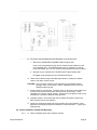
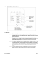
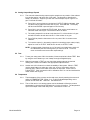
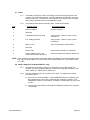
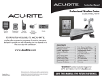
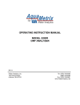
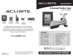
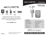
OPERATING INSTRUCTION MANUAL
MODEL 2200D/P91
DISSOLVED OXYGEN SYSTEM
REV. 8.0
Water Analytics, Inc.
100 School Street
Andover, MA 01810
978-749-9949
Toll free: 855-747-7623 (855-pHProbe)
Fax: 978-749-9961
www.WaterAnalytics.net
TABLE OF CONTENTS
GENERAL INFORMATION
1
SPECIFICATIONS
2
INSTALLATION
4
DESCRIPTION OF FUNCTIONS
8
START-UP AND OPERATION
12
OPERATING HINTS
17
UTILITY MENU
18
DIAGNOSTICS
20
TROUBLESHOOTING AND SERVICE
21
MODEL 2200D DISSOLVED OXYGEN ANALYZERS
AND MODEL P91 DISSOLVED OXYGEN SENSOR
INSTRUCTION MANUAL
1.0
GENERAL INFORMATION
The AquaMetrix Model 2200D Dissolved oxygen analyzer is a versatile industrial microprocessor
based instrument. Outputs are programmed through the menu with push buttons on the face of the
instrument. Calibration is also accomplished through the front panel menu. The instrument must be
used in conjunction with the AquaMetrix Model P91 dissolved oxygen sensor.
The instrument provides non-isolated 0-5 Vdc, 0-1 mA and isolated 4-20 mA analog outputs. The
analog outputs may be programmed to represent any segment of the measuring scale.
A membrane perforation alarm is provided which gives early warning of a membrane failure.
The instrument can also be used to take a temperature reading and one of the non-isolated analog
outputs can be used to give a continuous temperature signal.
The integrity of the system is ensured with a watch-dog timer and system alarm. A password
feature protects the stored values.
The instrument is housed in a NEMA 4X enclosure. The standard unit is provided with mounting
hardware for surface mount applications. Both panel and pipe mount kits can be ordered
separately.
Model 2200D/P91
Page 1
Instrument automatically returns to on-line operation if
accidentally left in menu mode
(This feature may be held disabled if desired)
2.0
SPECIFICATIONS
DISPLAY:
3 1/2 digit LED, 1/2" high digits
ACCURACY: % Saturation:
Ppm:
Temp:
± 1%
± 0.1
± 0.2°C
STABILITY: 0.1% of span per 24 hrs., non-cumulative
MEASURING RANGES:
D.O.: 0-20.00 ppm and 0-100% saturation, switch
selectable
Temperature: 0-40°C (32 to 104°F)
RESOLUTION:
POWER REQUIREMENTS:
98-132 Vac, 50/60 Hz (less than 10 VA)
Optional: 196-264 Vac, 50/60 Hz
REPEATABILITY: 0.1% of span or better
AMBIENT CONDITIONS:
-30 to 50°C (-22 to 122°F)
0 to 90% R.H. non-condensing
ENCLOSURE: NEMA 4X fibreglass reinforced polyester
enclosure with four 1/2” conduit holes and mounting
feet for surface mount
ANALOG OUTPUTS:
Non-isolated 0-1 mA, 100 ohms maximum load
Non-isolated 0-5 Vdc, 1000 ohms minimum load
Isolated 4-20 mA, 800 ohms maximum load
The isolated output is isolated from the input, ground
line power and all other outputs
Range Expand: The 4-20 mA analog output can be
made to represent any segment of the measuring
scale. Minimum segment is 10% of full scale.
Output Hold: The analog outputs are automatically
placed on hold during calibration or other setup
operations.
Temperature Output: The 0-5 Vdc output can be
programmed to follow either the process temperature
or dissolved oxygen.
% Saturation:
Ppm:
Temp:
0.1
0.01
0.1°C
RESPONSE TIME: 20 seconds to 90% of value upon
step change at 20°C
MOUNTING CONFIGURATIONS:
Standard is surface mount
Optional panel mount hardware. Part No. 35-68
Optional pipe mount hardware. Part No. 35-69
NET WEIGHT: 3 1/2 lbs. (1.6 kg)
TEMPERATURE COMPENSATION:
Automatic 0 to 100°C (32 to 212°F)
ALTITUDE COMPENSATION:
Automatic 0 to 40°C (32 to 104°F)
DIAGNOSTICS:
When system erros is indicated, call STATUS to obtain
condition code. On-board simulated input to aid in
troubleshooting to obtain condition code.
MEMBRANE ALARM:
A relay activates if membrane is perforated.
TEST:
Display value and analog outputs can be set manually
to any value for testing and diagnostic purposes. This
feature allows the outputs to be tested independently
of process value.
MODEL 2200D-X-2-X ADDITIONAL
FEATURES
CONTROL RELAYS:
Two relays can be independently set for
operation in response to rising or falling
value and for fail-safe operation. Deadband
(hysteresis) independently adjustable.
Rating: 5A 115/230 Vac, 5A 30 Vdc. SPDT
ALARM RELAY:
High-Low with fixed deadband of 2% of full
scale. Normal or fail-safe operation.
Rating: 5A 115/230 Vac, 5A 30 Vdc. SPDT
SAFETY & SECURITY:
Non-volatile memory (EEPROM)
Passcode protected if selected
Watch-dog timer monitors microprocessor
Model 2200D/P91
RELAY INDICATORS:
Three LEDs indicate status or the three
relays
P91 SENSOR
Page 2
TEMPERATURE RANGE:
0-40°C (32 to 104°F)
WETTED MATERIALS:
PVC and Teflon F.E.P.
FAILURE ALARM:
5A SPDF relay closes if membrane is punctured. LED on panel
is illuminated
CABLE:
Integral 8 m (26 ft.) Maximum distance to analyzer 300 m (1000
ft.)
REPLACEMENT CARTRIDGE:
Part No. P91-D. Hermetically sealed.
MOUNTING HARDWARE
FLOTATION MOUNTING:
Model MHBF consists of ball float, extension pipe, swivel
bracket, junction box and 50 feet of interconnect cable
SUBMERSION MOUNTING:
Model MHDS consists of 5 ft. PVC pipe, junction box and 50 feet
of interconnect cable
FLOW-THROUGH ASSEMBLY:
Model MHFT. Pipe connections are 2” NPT
Model 2200D/P91
Page 3
3.0
INSTALLATION
3.1 Location
3.1.1
Locate the instrument within the reach of the cable provided for the P91 sensor.
3.1.2
Select an installation site which is:
• free of mechanical vibrations
• reasonably clean and dry
• protected from falling corrosive fluids within the ambient temperature and humidity
specifications
• remote from high voltage relay and power switches
3.2 Type of Mounting
3.2.1
If the instrument is to be pipe or panel mounted a special hardware kit will be
required. For panel mount order part number C35-68. For pipe mount order part
number C35-69. Instructions for both types of mounting will be included with the
kits.
3.2.2
For surface mounting, four feet brackets, together with fastening screws, are
provided with the instrument. These should be fastened to the back of the
instrument and then it may be screwed or bolted in the selected location.
3.3 Conduit Connections
3.3.1
Four 1/2" conduit holes are provided in the bottom of the enclosure. One of these is
fitted with an approved water tight plug. To maintain NEMA 4 integrity, approved
conduit hubs must be used to connect conduit. The hubs must be connected to the
conduit before being connected to the enclosure. Any unused conduit holes must be
closed with water tight plugs or connectors.
3.3.2
For convenience of internal connections the right conduit hole (viewed from the
front) should be used for power connection; the next hole to the left for relay
outputs; the next hole to the left for analog outputs and finally the fourth hole for
sensor input.
3.4 Electrical Connections
CAUTION: The instrument operates from line voltage. This constitutes a possible shock hazard.
Ensure that line power is removed before attempting connections. Note: A separate
source of line power may have been connected to the floating relay contacts.
3.4.1
Model 2200D/P91
To access the terminal strips open the door of the instrument and then unscrew the
captive retaining screw near the upper right hand corner of the panel. Now swing
open the panel to reveal the terminal strip on the power supply circuit board and the
smaller terminal strip on the back of the swing-out board.
Page 4
3.5 Sensor Installation, Flotation Mounting
3.5.1
Refer to diagram below and proceed as follows:
a) Fasten elbow to 90-inch long pipe
NOTE: Thread sealant (Teflon tape) is recommended on all mounting hardware
and sensor threads to avoid leaks
b) Fasten adapter pipe with union to elbow
c) Insert adapter pipe with union into flotation ball and tighten union lock ring to
secure float assembly
Model 2200D/P91
Page 5
d) The sensor may be attached to float assembly in one of two ways:
1. With sensor EXTENDED FROM BOTTOM of flotation ball:
Insert 12-inch long extender pipe into the flotation ball and fasten it to the
end of adapter pipe. This will extend the sensorʼs membrane 12 inches
below the flotation ball. NOTE: Extender pipe supplied only when ordered.
2. With the sensor membrane FLUSH WITH BOTTOM of flotation ball:
Disregard using extender pipe and proceed with Step e).
e) Route sensor cable through assembled pipe sections, starting from bottom
section, and fasten sensor to pipe.
CAUTION: Do not remove measuring cell cartridge from hermetically sealed
package until it is to be used in step f). (Membrane will dry out and
damage measuring cell).
f)
Install measuring cell cartridge. Unfasten union nut from sensor and make sure
to remove any moisture from cavity area and brass contact strips. Insert
cartridge in its correctly “keyed” position. Fasten union not tightly so that O-ring
compresses to create an effective water-tight seal.
g) Calibrate system in accordance with the procedure described in Section 5.3
before placing sensor into operation.
h) Install pivot mounting bracket and mount junction box on the bracket. Insert
pipe/sensor assembly through the bracket to the desired position. Tighten pipe
locking screw.
3.6 Sensor Installation, Submersion Mounting
3.6.1
Model 2200D/P91
a) Refer to diagram below and proceed as follows:
Page 6
b) Route sensor cable through pipe and fasten sensor to pipe. The use of thread
sealant (Teflon tape) on all mounting hardware and sensor threads is
recommended to avoid leaks.
CAUTION: Do not remove measuring cell cartridge from hermetically sealed
package until it is to be used in step b). (Membrane will dry out and
damage measuring cell).
c) Install measuring cell cartridge. Unfasten union nut from sensor and make sure
to remove any moisture from cavity area and brass contact strips. Insert
cartridge in its correctly keyed position. Fasten union tightly so the O-ring
compresses to create an effective water-tight seal.
d) Mount the junction box within reach of the sensor cable.
e) Calibrate system in accordance with the procedure described in Section 5.3
before placing sensor into operation.
3.6.2
The terminal strip on the power supply board at the back of the instrument is labeled
for power supply, relay outputs and analog outputs. Connect wiring in accordance
with this labeling. CAUTION: Connecting the line voltage power supply to incorrect
terminals may cause serious damage.
3.7 Probe Connections
3.7.1
The interconnect cable as supplied will normally be connected to the sensor cable
in the junction box. If this is not the case, connect the six wires and the shield of the
extension cable to the numbered wires in the junction box as shown below:
Extension Cable
Blue
Red
Black
Green
White
Yellow
Shield
Junction Box
1
2
3
4
5
6
Unnumbered (Green/Yellow)
3.7.2
Connect the six wires of the interconnect cable to the terminal strip on the swing-out
board being sure to match colors as printed on the board. Connect the shield to the
terminal post located above the terminal strip.
3.7.3
Running the sensor and interconnect cable in 1/2” metal conduit for protection
against moisture and mechanical damage is recommended. Do not run power or
control wiring in the same conduit (“electrical noise” may interfere with sensor
signal).
Model 2200D/P91
Page 7
4.0
DESCRIPTION OF FUNCTIONS
4.1 Overview
4.1.1
The Model 2200D is a microprocessor based dissolved oxygen analyzers are
designed for industrial applications. They operate in conjunction with the
AquaMetrix P91 sensor. The software in the unit makes the instrument very easy to
operate and maintain.
4.1.2
The outputs include voltage-free relay contacts and industry standard analog
transmission signals. A relay to indicate a perforated membrane is provided. The
analog output signals transmit low power signals to peripherals such as data
recorders or control systems.
4.1.3
The software is designed for ease of operation. It uses a simple menu with all items
indicated on the panel. The user interface consists of six buttons on the front panel.
The buttons are scanned and responded continuously. In addition, an extensive
system checking for values and parameters is performed by the software. All of the
operating parameters are stored in non-volatile memory, without the need of a
battery.
4.1.4
The Model 2200D operates like a normal analog converter with a number of
additional functions made possible by the microprocessor in the instrument.
Model 2200D/P91
Page 8
Some of these are:
•
•
•
•
•
•
•
•
Recall and easy adjustment of relay and output parameters
Push button calibration
A HOLD function for outputs
Continuous sensor check during measurement
Continuous self check and watch-dog timer to ensure correct operation
Password protection of stored values
Temperature Output
Simulated input for testing
4.2 Calibration
4.2.1
The 2200D is calibrated at the factory, with the sensor purchased with the
instrument. However, the system should be field calibrated when installed and from
time to time thereafter. The calibration procedure is given in Section 5.3.
4.3 Temperature Compensation
4.3.1
A temperature sensor in the P91 sensor provides the means of continually
compensating the D.O. reading for variation in the temperature of the process.
4.4 Relay Outputs (Model 2200D-X-2 only)
4.4.1
Three SPDT relays are provided. The normally open contacts, NO, are open when
no alarm or control is active.
4.4.2
The two control relay can be programmed to close on either rising or falling D.O.
They can be set to close at any point on the scale. The deadband, sometimes
termed hysteresis, defines the point at which the relays open. See Sections 4.8,
5.8, and 5.9.
4.4.3
The third relay functions as a high-low alarm. It has two programmable setpoints
(high and low). The deadband is fixed at 2% of full span. This relay is also
activated in the event of a perforated membrane. (See Section 4.5) The alarm
contact can be programmed to also signal memory loss in the 2200D controller.
See Section 4.8, 5.12, and 5.13.
4.4.4
All relays can be programmed for "fail-safe" operation which reverses the normal
operation of the relay. In this mode the relays will fail-safe (transfer) in the event of
power failure.
4.5 Membrane Alarm Relay
4.5.1
A single pole double throw relay is provided to give an output in the event of a
perforated membrane. This relay is also the high/low alarm relay in the Model
2200D-X-2.
4.5.2
This relay can be programmed to also signal memory loss. See Section 4.8.
4.5.3
When this relay is activated the contacts will close and FAIL LED for Model
2200D-X-1 and STATUS LED for Model 2200D-X-2 will be indicated on the panel.
Model 2200D/P91
Page 9
4.6 Analog Outputs
4.6.1
The analog output signals consist of a non-isolated 0-1 mA, 0-5 Vdc, and isolated 420 mA signals.
4.6.2
From the factory all of the analog outputs have a linear range corresponding to the
full range of the instrument. The 4-20 mA output can be programmed to another
linear range by entering two values:
• Output High: This is the D.O. value at which you wish to have 100% output.
• Output Low:
This is the D.O. value at which you wish to have 0% output.
4.6.3
When programming, you must ensure that the output range has a span of at least
10% of the full range of the instrument. For applications that require the output to
decrease as the process value increases, i.e. an inverted output, the Output High
value will be less than the Output Low. See Section 5.4.
4.6.4
The instrument may be used to measure the temperature of the process either in
Celsius or in Fahrenheit. The 2200D does not control temperature but the 0-5 Vdc
and 0-1 mA analog outputs can be dedicated to follow the process temperature.
See Sections 5.6.
4.7 Operation Menu
4.7.1
The operation menu allows the user to recall and to adjust the parameters, required
by the analyzer functions.
4.7.2
When the analyzer is powered up, the program will display D.O. readings. None of
the LEDs in the operation menu will be illuminated.
4.7.3
Five buttons on the panel are used to operate the menu. Use the CALL button to
step through the items in the menu, one at a time. The red LEDs beside each item
makes it very easy to follow the menu. The function of the RUN button is to return
to the on-line D.O. display from anywhere in the menu. The analyzer has a built-in
timer which, when enabled, by DIP Switch 7 Bank S1 (Section 4.8), returns the
program to RUN mode if no button has been pressed for 10 minutes. This time-out
has the same effect as pressing the RUN button.
4.7.4
When in the menu mode, the display initially shows the current value of the
parameters, such as the Setpoint of the control relay, while putting all of the outputs
on hold. The two arrow buttons are used to adjust the display value up or down. To
accept the new value press ENTER twice. While the value on the display is being
changed, the relay outputs and the analog outputs remain on hold.
The items that appear in the operation menu are:
•
•
•
•
•
•
•
•
Password
% Sat/ppm
Test
Calibration
Temperature
Status
Output High
Output Low
In addition, Model 2200D-X-2 has the following items:
•
•
•
•
•
Model 2200D/P91
Relay A Setpoint
Relay A Deadband
Relay B Setpoint
Relay B Deadband
Alarm Relay High
Page 10
• Alarm Relay Low
4.8 DIP Switches
4.8.1
The controls which are frequently used in the normal operation of the instrument are
all accessible on the control panel. Some switches, which are infrequently used are
located on the back of the swing-out board.
4.8.2
The DIP switches are scanned on RESET, power-up and every time the instrument
is taken into the menu mode. Therefore, after changes to the DIP switch settings,
you must take the unit offline by pressing CALL in order for the instrument to scan
the new DIP switch values.
4.8.3
The following table describes the use of the 16 DIP switches:
DIP Switch
Bank S1
1
2
3
4
5
6
7
8
Description of Use
Selects temperature unit
Enables use of Password Feature
Fail Safe mode for Relay A
(for Model 2200D-X-2 only)
Direction of Control Relay A
(for Model 2200D-X-2 only)
Alarm Relay to Activate for Memory Loss
Fail Safe mode for Alarm Relay
Auto Return from menu if no button pressed
0-5 Vdc / 0-1 mA selector
Switch
OFF
Switch
ON
°F
YES
NO
°C
NO
YES
Rising
Falling
YES
NO
NO
Temperature
NO
YES
YES
D.O.
NO
Rising
YES
Falling
Dip Switch
Bank S2
1
2
3
4
5
6
7
8
Model 2200D/P91
Fail-safe for Relay B
Direction of Control for Relay B
Reserved
Reserved
Reserved
Reserved
Reserved
Reserved
Page 11
4.9 Output Hold
4.9.1
Output hold, is a function which freezes all output signals at the last value to prevent
the occurrence of wild distortions during programming and maintenance.
4.9.2
When the Operation Menu is entered by pressing CALL, the alarm relays and the
analog outputs are automatically placed on hold and remain on hold until the
instrument returns to on line. The output hold will remain for a maximum of 10
minutes after the last button was pressed, if this feature has been enabled. See
Section 4.8.
4.10 Parameter and Operation Checking
4.10.1 The instrument continuously checks all parameters in its memory, while taking D.O.
readings. When it detects an invalid value, it flashes the LEDs in the operation
menu to indicate the parameter is at fault. You must then access the operation
menu to take corrective actions.
4.11 Simulated Input for Testing
4.11.1 TEST is function for test and diagnostic purposes. Values can be simulated
internally and adjusted with the arrow buttons to set display reading and analog
outputs to any desired value without disrupting instrument calibration.
4.12 Utility Menu
4.12.1 The Utility Menu is provided to enable authorized personnel to change the range
and fine tune the analog . See Section 7.0.
4.13 Watchdog Timer and Self Diagnostics
4.13.1 The 2200D continuously monitors the condition of all key components of the
measuring system to ensure that the measurements are reliable. Invalid entries and
memory loss are indicated on the panel. See Section 8.0.
5.0
START-UP AND OPERATION
5.1 Password
5.1.1
To enter the menu press CALL then PASSWORD will be indicated. With each
press of CALL you will step through the menu. When the last item is reached the
menu wraps around to “%sat/ppm”. If you have enabled PASSWORD by placing
DIP Switch 2 Bank S1, in the off position you must enter the password “6” when
PASSWORD is indicated if you wish to change any stored value. You do not need
to enter the password to proceed to other items in the menu for recall of stored
values.
If PASSWORD has not been enabled you do not need to enter the password to
change stored values.
Model 2200D/P91
Page 12
5.2 Percent Saturation/ppm
5.2.1 The instrument provides measurement of dissolved oxygen in either percent
saturation or ppm. In ppm measurement the reading is automatically compensated
for temperature changes in the medium.
a) To select units of measurement enter the menu by pressing CALL to indicate
%sat/ppm.
b) Press the UP arrow button to select %sat or the DOWN arrow button or select
ppm.
c) Press RUN to return to on line or press CALL for another menu selection.
5.3 Calibration
5.3.1
To calibrate the instrument you will need a container of fresh clean water. For best
results a bubbler such as that used in a tropical fish tank should be in the container.
a) Clean the sensor with a soft cloth and mild soap solution.
b) Place the sensor over the water container for a few minutes. (There is no need
to remove it from the float if so installed.)
c) Press CALL to enter the menu.
d) If the password function is enabled, enter the password then press CALL to
illuminate the “%sat/ppm” indicator. If the password function is not enabled,
“%sat/ppm” will illuminate at the first press of CALL.
e) Use the UP arrow button to illuminate the %sat LED located to the right of the
display.
f)
Press CALL twice to illuminate the CALIBRATION indicator.
g) Use the arrow buttons to make the display read 100.0.
h) Press ENTER as soon as the reading stabilizes. The display will flash until
ENTER is pressed again to confirm entry.
i)
If you wish to change the measuring unit to ppm, press CALL a number of times
to return to “%sat/ppm” and change ppm with the down button.
j)
Press RUN to return to on line measurement.
NOTE: If a major change is necessary to make the display read 100% the display
will flash when you press ENTER. This is to warn that you may have made
a mistake such as using “stale” water. If you are confident your procedure
was correct, press ENTER a second time. Otherwise, repeat the calibration
procedure by pressing CALL a sufficient number of times to go through the
menu and return to CALIBRATION.
Model 2200D/P91
Page 13
5.4 Analog Output Range Expand
5.4.1
The 4-20 mA isolated analog output may be spread over any section of the scale as
long as that section is at least 10% of full scale. The best way to describe this
setup is by example. Suppose you wish the 4-20mA output to span 4 ppm to 10
ppm. Proceed as follows:
a) Press CALL as many times as required until OUTPUT HIGH is indicated. Now
use the arrows to make the meter read 10 ppm. Press ENTER. The display
will flash until ENTER is pressed again to confirm entry.
b) Press CALL once to indicate OUTPUT LOW. Now use the arrow buttons to
make the meter read 5 ppm. Press ENTER twice as above.
c) The analog output will now be at 4 mA when the D.O. of the solution is 5 ppm
and will increase to 20 mA when the D.O. of the solution is 10 ppm.
d) Press RUN to place the instrument on line or press CALL for another menu
selection.
e) To invert the output (i.e. decreasing output for increasing process value) simply
adjust for 4 mA on OUTPUT HIGH and for 20 mA on OUTPUT LOW.
NOTE: A range expand of less than 10% of full scale is an invalid entry which will
be indicated by the LED flashing when you return to RUN. To correct,
return to the menu and correct the output settings.
5.5 Test
5.5.1
To test your setup press CALL the number of times required to indicate TEST. Now
by using the arrow buttons you can “sweep” through the digital display.
5.5.2
With the instrument in TEST you can check the analog output at any desired
reading with a meter connected to the appropriate output terminals.
5.5.3
Another use of this feature is to check the stability of the system. When in TEST,
use the arrow buttons to select any value, say 10 ppm. Now return online by
pressing RUN. Return to the meter some hours or days later. Press CALL to
indicate TEST. If the instrument is still in calibration and if no one has interfered the
meter should read 10 ppm.
5.6 Temperature
5.6.1
The temperature of the process can be read at any time by entering the menu and
calling for TEMPERATURE. Either °C or °F will be indicated depending on the
position of DIP switch No. 1. Bank S1. See Section 4.8.
5.6.2
The 0-5 Vdc and 0-1 mA analog outputs can be dedicated to follow the process
temperature by simply placing DIP switch No. 8 in the off position. The temperature
span of the output is set to the utility menu. See Section 4.8 and 7.4.
Model 2200D/P91
Page 14
5.7 Status
5.7.1
The 2200D continuously checks the integrity of all stored data and monitors the
condition of the measuring system. If a fault is detected, the FAIL LED above the
display will turn red. The STATUS in the operation menu will provide a numerical
code, giving a possible cause and a suggested remedy.
5.7.2
The following table shows the display codes, causes and remedies:
Code
Possible Cause
Suggested Remedy
0
Normal Condition
No action required
1
Reserved
2
Temperature Sensor off Scale
Verify process. Check for open or short
connections.
3
D.O. reading off Scale
Verify process. Check for open or short
connections.
4*
Memory Loss
Call your Aquametrix representative
5
Reserved
6
Sensor Fault
Check probe membrane for perforation
7
Factory Setting in force, as a
result of the ESCAPE procedure
Perform procedure according to Section 9.2
NOTE: Code 4 could be a serious failure so the alarm relay will in addition to the red illumination of the
FAIL LED for Model 2200D-X-1 and STATUS LED for Model 2200D-X-2, if DIP switch 5 Bank
S1 is OFF.
5.8 Relay A Setpoint (For Model 2200D-X-1 only)
5.8.1
As shipped from the factory, Relay A is configured to control decreasing D.O.
However, you may change the direction of control by changing the position of DIP
switch 4 Bank S1. Please refer to Section 4.8.
5.8.2
The relay setpoint may be at any place on the scale. To establish the setpoint
proceed as follows:
a) Press CALL to enter the MENU. If the PASSWORD function is enabled, enter
the password then press CALL to illuminate the “%sat/ppm” indicator. If the
PASSWORD function is not enabled, “%sat/ppm” will illuminate at the first press
of CALL.
b) Use the down arrow button to illuminate the PPM LED located to the right side
of the display.
Model 2200D/P91
Page 15
c) Press CALL the required number of times until RELAY A SETPOINT is
indicated. Now use the arrows to make the display read the desired value.
Press ENTER. The display will flash until ENTER is pressed again to confirm
entry. A LED above the display indicates when Relay A is activated.
d) Press RUN to place the instrument on line or press CALL for another menu
selection.
5.9 Relay A Deadband (For Model 2200D-X-2 only)
5.9.1
If you have configured the instrument with the DIP switch on the back of the panel
for falling D.O. you will wish to have the deadband (sometimes called “hysteresis”)
at a higher value than the setpoint. If you have established a setpoint of 3 ppm you
may wish the deadband to be between 6 ppm and 3 ppm. Proceed as follows:
a) Enter the menu and press CALL the required number of times to indicate
RELAY A DEADBAND. Use the arrow buttons to make the display read the
desired value (in this example, 6). Press ENTER. The display will flash until
ENTER is pressed again to confirm the entry.
b) In this example, after the instrument has been returned to RUN, the relay will be
energized when the D.O. falls to 3 ppm and will remain energized until the
reading rises above 6 ppm.
c) When Relay A is activated a LED above the display will be illuminated.
d) Press RUN to place the instrument on line or press CALL for another menu
selection.
5.10 Relay B Setpoint (For Model 2200D-X-2 only)
5.10.1 Relay B Setpoint is configured in the same way as Relay A Setpoint. See Section
5.8. A LED above the display indicates when Relay B is activated.
5.11 Relay B Deadband (For Model 2200D-X-2 only)
5.11.1 Relay B Deadband is configured in the same way as Relay A Deadband. See
Section 5.9.
NOTE: A deadband setting on the wrong side of the setpoint in an invalid entry
which will be indicated by the LED flashing when you return to RUN. To
correct return to the menu and change the deadband setting or, if the
direction of control is the problem, change the position of the relevant DIP
switch. See Sections 4.8 and 5.9.
5.12 Alarm High (For Model 2200D-X-2 only)
5.12.1 The instrument is fitted with a relay, which is set to activate on both high and low
alarm conditions. The deadband is factory set. To set the ALARM HIGH proceed as
follows.
a) Enter the menu and press CALL until ALARM HIGH is indicated. With the
arrow buttons make the display read the desired alarm value. Press ENTER.
The display will flash until ENTER is pressed again to confirm the entry.
b) Press RUN to place the instrument on line, or press CALL, for another menu
selection.
5.13 Alarm Low (For Model 2200D-X-2 only)
5.13.1 a) Press CALL until ALARM LOW is indicated. With the arrows make the meter
read the desired value. Press ENTER. The display will flash until ENTER is
Model 2200D/P91
Page 16
pressed a second time to confirm entry.
b) Press RUN to place the instrument on line, or press CALL, for another menu
selection.
NOTE: A low alarm point higher than the high alarm point is an invalid entry, which
is indicated by the LED flashing when you return to RUN. To correct, return
to the menu and reset the alarm points.
6.0
OPERATING HINTS
6.1 Cell Care
6.1.1
If the sensor membrane is exposed to the atmosphere for more than 24 hours, the
electrolyte inside the membrane can dry out. If this occurs, the cartridge will need
to be replaced. To avoid membrane dry-out, place the sensor in a container of
clean drinking water until it can be reinstalled into the aeration basin.
6.1.2
Sensor cartridges can be stored for up to 5 years if the seal on its storage container
is not broken and the temperature is between 70°F and 80°F with 50 to 80%
humidity. Do not store sensor cartridges at temperatures below freezing point
(32°F). The electrolyte solution will crystallize at 25-30°F.
6.1.3
Cleaning the sensor membrane before each calibration is recommended. Use soft
cloth and mild soap solution to remove material from the membrane. When
cleaning, take care to avoid puncturing the sensor membrane. Should this occur,
the complete sensor cartridge must be replaced.
6.2 Calibration
6.2.1
Depending on the application, system calibration should be performed periodically
to maintain measurement accuracy. Frequent checks are suggested until the
operational history indicates the optimum period between checks.
6.3 Reset
6.3.1
The instrument can be reset without losing calibration or any of the stored values by
pressing and releasing the S9 reset button (located at the bottom of the board near
the center) This action is equivalent to turning the power off and on.
6.4 Output Hold
6.4.1
It may be useful during some system maintenance procedures to place the relay
and analog outputs on hold. To accomplish this simply press CALL. To return to on
line operation press RUN.
NOTE: To safeguard against the operator forgetting to press RUN the instrument
will automatically go back on line ten minutes after the last button was
pressed provided this feature has been enabled by placing DIP switch No.7,
Bank S1, in the ON position.
7.0
UTILITY MENU
7.1 Utility Menu Functions
7.1.1
The Utility Menu enables authorized personnel to perform the following:
•
•
•
•
Model 2200D/P91
Adjust the temperature output range.
Adjust the offset and span of the 0-1 mA/ 0-5 Vdc output
Adjust the offset and span of the 4-20 mA output
Perform the altitude compensation
Page 17
7.2 Access to Utility Menu
7.2.1
The Utility Menu is protected by password. To access the Utility Menu press and
hold both RUN and ENTER for five seconds until the PASSWORD LED illuminates.
The RUN LED will flash to warn that Utility Menu is in use. Now with the arrow keys
make the display read the password, "7". Press ENTER.
7.2.2
The Utility Menu is entirely separate from the Operation Menu but uses the same
LED display. Press CALL to step through the menu items.
Below is the cross-reference between menu items:
Display LED
Meaning in Utility Menu
Output High
Output Low
%Sat/ppm
Test
Calibration
Temperature
Status
Temperature Output 100% (5 Vdc)
Temperature Output 0% (0 Vdc)
0-1 mA / 0-5 Vdc Output Adjust Low
0-1 mA / 0-5 Vdc Output Adjust High
4-20 mA Output Adjust Low
4-20 mA Output Adjust High
Altitude Compensation
7.3 Temperature Output
7.3.1
The 0-5 Vdc and 0-1 mA outputs may be programmed to track the temperature of
the process. The factory outputs have a linear range corresponding to 0°C to 40°C,
(or 32°F to 104°F.) Suppose you wish the output to span 10°C to 45°C. Proceed
as follows:
a) Enter the Utility Menu as described in 7.2.1.
b) Press CALL to indicate OUTPUT HIGH, which is the “Temperature output,
100% point” in the Utility Menu. (See table in 7.2.2). Now use the arrow button
to show 45.0 on the display. Press ENTER. The display will flash until ENTER
is pressed again to confirm entry.
c) Press CALL to indicate OUTPUT LOW, which is the “Temperature output, 0%,
point” in the Utility Menu. (See table in 7.2.2). Now use the arrow buttons to
show 10.0 on the display. Press ENTER twice as above.
d) Press RUN to return to on line or press CALL to proceed to another item in the
Utility Menu.
7.4 Adjust 0-1 mA / 0-5 Vdc Output
7.4.1
It may be desirable to fine tune the 0-1 mA / 0-5 Vdc output to take into account the
characteristics of your particular loop. The following method involves a high and
low calibration and requires the use of a digital multi-meter (DVM). Proceed as
follows ignoring the instrument display:
a) Turn off the power to the instrument. Connect your DVM to the 0-5 Vdc output
terminals on the power supply board.
b) Turn on the power. Enter the Utility Menu as described in 7.2.1.
c) Press CALL to indicate “%sat/ppm”, which is "0-1 mA/ 0-5 Vdc output adjust,
low" in the Utility Menu (See table in 7.2.2). Use the arrow keys to make your
DVM read 1.25V. Press ENTER twice to confirm.
d) Press CALL to indicate TEST, which is "0-1 mA / 0-5 Vdc Output adjust, high" in
the Utility Menu (See table in 7.2.2.) Use the arrow keys to make your DVM
read 3.75V. Press ENTER twice to confirm.
Model 2200D/P91
Page 18
e) Press RUN to return to on line or press CALL to proceed to another item in the
Utility Menu.
7.5 Adjust 4-20 mA Output
7.5.1
It may be desirable to fine tune the 4-20 mA isolated output to take into account the
characteristics of your particular loop. Before deciding that the adjustment is
necessary, be aware of the "Output High" and "Output Low" settings you may have
programmed as described in Section 5.4. The following method involves a high and
low calibration and requires the use of a Digital Multimeter (DVM). Proceed as
follows ignoring the instrument display.
a) Turn off the power to the instrument. Connect your DVM to the 4-20 mA output
terminals on the power supply board.
b) Turn on the power. Enter the Utility Menu as described in 7.2.1.
c) Press CALL to indicate CALIBRATION, which is "4-20 mA Output adjust, low" in
the Utility Menu (See table in 7.2.2.) Now use the arrow keys to make your
DVM read 8 mA. Press ENTER twice to confirm.
d) Press CALL to indicate TEMPERATURE, which is "4-20 mA Output adjust,
high" in the Utility Menu (See table in 7.2.2). Now use the arrow keys to make
your DVM read 16 mA. Press ENTER twice to confirm.
e) Press RUN to return to on line or press CALL to proceed to another item in the
Utility Menu.
7.6 Altitude Compensation
7.6.1
The instrument can be compensated for the altitude at which it is located by the
following procedure:
a) Go to the UTILITY MENU as described in 7.2.1.
b) Press CALL to indicate “STATUS” which is “ALTITUDE COMPENSATION” in
the Utility Menu.
c) Adjust the display to your altitude in thousands of feet. For example, 0.34 on
display corresponds to an altitude of 340 feet. Press ENTER. The display will
flash until ENTER is pressed again to confirm entry.
d) The supported altitude range is from –1,000 to 30,000 ft. (-305 to 9,144 m) or –
1.00 to 30.00 on the display. As shipped from the factory the altitude is set to
zero. i.e. sea level.
e) Press RUN to go on line, or CALL to proceed to another Utility Menu item.
8.0
DIAGNOSTICS
8.1 Description
8.1.1
The 2200D has diagnostic features which alerts the operator to invalid entries and
memory loss. Invalid entries are indicated by the flashing of the appropriate menu
LED. The flashing will commence after RUN is pressed and will continue until the
errors are corrected. Memory loss is indicated by the flashing of TEST and by the
alarm relay if enabled by DIP Switch No. 5 of Bank S1. See Section 4.8.3.
8.2 Invalid Output
8.2.1
Model 2200D/P91
Invalid output will be indicated if the expanded range is less than 10% of full scale.
To correct, refer to Section 5.4.
Page 19
Model 2200D/P91
Page 20
9.0
TROUBLESHOOTING AND SERVICE
9.1 Isolate the cause
9.1.1
When a measurement problem occurs, the first step is to try to isolate the cause. If
the 2200D is powered, go through the menu and check your settings. A convenient
way to do this is to call TEST. See Section 5.5.
9.1.2
If your 2200D appears dead or intermittent, check the breaker, make sure that the
instrument is set up for the available line voltage and make sure the line voltage is
actually available at the terminals. Now measure that sufficient voltage is available
at all times; it should be 98 Vac to 132 Vac or 187 Vac to 243 Vac respectively.
Shut line power off, making sure it is off. CAUTION: Power to the relays may be
supplied from a separate source, shut it off too. Check and if necessary replace the
internal 0.25A fuse. Push the connector of the ribbon cable firmly into its socket. If
these steps do not solve the problem it may be necessary to replace the power
supply board. See Section 9.3.1 below.
9.1.3
If the process value seems wrong, clean the sensor as described in Section 6.1.3.
Inspect the sensor, wire, terminal block connections and interconnections.
Calibrate and resume operation.
9.1.4
To find out whether the problem is in the sensor, or in the analyzer, use the selftesting features. Leave the instrument in RUN mode and proceed as follows:
a) Move the slide switches S40 and S41 on the back of the swing-out panel from
position "ON LINE" to position "TEST."
b) Press CALL to enter the menu and go to “%sat/ppm.”
c) Set the D.O. simulation DIP switch Bank S42 switch No. 1, On, Switches No. 2,
3, and 4, Off. The display should show 4 ppm ±5%.
d) Now proceed to turn each of the other S42 switches On with the remaining
switches Off.
The display should read within 5% of 10 ppm with switch 2 On, 16 ppm with
switch 3 On, and 20 ppm with switch 4 On.
If this is the case the analyzer is in order and the problem is with the probe.
e) Return S40 and S41 to “On line” and ensure that all S42 switches are Off.
9.1.5
a) To check the temperature channel move the slide switches S40 and S41 from
position “On line” to position “TEST”.
b) Set the DIP switch 1 Bank S1 On.
c) Go to the TEMPERATURE menu item.
d) Set the temperature simulation DIP switch Bank S43 switch No. 1 On, switches
No. 2 and 3 Off. The display should show 10 degrees Celsius ±5%.
e) Now proceed to turn each of the other S43 switches On with the remaining
switches Off.
The display should read within 5% of 25°C with Switch 2 On and 35°C with
Switch 3 On.
If this is the case the analyzer is in order and the problem is in the sensor.
Otherwise the problem is in the analyzer.
f)
Model 2200D/P91
Return S40 and S41 to “On line” and ensure that all S43 switches are Off.
Page 21
9.2 Escape
9.2.1
If the instrument appears to be "DEAD", for example not responding to the buttons,
or not performing on line measurement and control, always try the reset feature first,
as described in 6.3.1.
9.2.2
a) The "ESCAPE" procedure is to be used normally at the factory only, when the
unit is powered with a new MCU. As a result, the internal non-volatile memory
(EEPROM) is "FORMATTED" and the factory values are loaded into it.
b) The "ESCAPE" procedure is to be used if a unit is serviced for a new MCU
insertion, in case where the MCU was not calibrated at Water Analytics, or in
case of a memory loss problem, when so advised by Water Analytics service
support.
9.2.3
Before performing the "ESCAPE" procedure it is important to know that this
procedure provides the option to erase all programmed values and replace them
with the factory set default values. This is also true for the control setpoints and
deadbands, then alarm settings and the analog outputs scaling. Also, the
temperature and the D.O. calibration points will be set to their initial values. This
means, that the temperature and the D.O. calibration must be performed after an
“ESCAPE” procedure. After that, all the control, alarm and scaling parameters
mentioned above must be set to the user values.
9.2.4
To perform the ""ESCAPE"" proceed as follows.
a) Turn off the power.
b) Press and hold the RUN button for about 3 seconds, while turning on the power.
The FAIL LED will turn on (For Model 2200D-X-1 only) and STATUS LED will
become red (For Model 2200D-X-2 only) and status code 7 will be obtained to
show that the ESCAPE procedure was just performed.
9.2.5
After the "ESCAPE" procedure it is necessary to do the following:
a) Tune the analog outputs and the temperature output span to suit your particular
application and loop. See Sections 7.3, 7.4, and 7.5.
b) Calibrate the system, as described in Section 5.3.
c)
Set up the user values for:
• Output High and Low - See Section 5.4. (For Model 2200D-X-2)
• Control Relay - See Sections 5.8 and 5.9.
• Alarm Relay - See Sections 5.12 and 5.13.
d) After all the above operations are performed the FAIL LED will turn off (For
Model 2200D-X-1) and STATUS LED will turn green (For Model 2200D-X-2)
and Status “0” should be obtained.
e) The unit may be tested now, using the TEST menu item (See Section
5.5), or the built-in self-testing feature, (See Section 9.1.4)
f)
Bring the unit on line for measurement and control.
9.3 Printed Circuit Board Replacement
9.3.1
Model 2200D/P91
a) To replace printed circuit boards or relays shut off all power to the 2200D,
including any independent power to the relay contacts. Make a record of the
external wiring, then disconnect the wires. Unplug the ribbon cable connector.
Page 22
b) The power supply circuit board is fastened to the back of the enclosure by four
screws, remove the screws and the board is free. Reverse the procedure to
mount a replacement board.
c) The microprocessor circuit board is located on the swing-out assembly behind
the door. Swing the assembly out, lift it up to unseat the lower hinge pin (the
upper hinge pin is spring loaded.) The assembly is now free. The circuit board
is fastened to the front panel by three screws. Remove the screws to release
the circuit board.
9.4 Sensor Fault
9.4.1
If the membrane of the sensor cartridge is pierced, the alarm relay contacts will
close and the FAIL LED (For Model 2200D-X-1) and STATUS LED (For Model
2200D-X-2) will be illuminated. However, it may be difficult to see the leakage with
the naked eye. A slight pressure on the membrane with a finger will produce a drop
of liquid. The cartridge must be replaced. See Section 9.4.3.
9.4.2
With operating time silver oxide will build up on the anode (silver wire). When the
anode becomes brown as a result of the deposit, it is time to replace the sensor
cartridge.
9.4.3
To replace the sensor cartridge, unscrew the retaining nut, remove and discard the
spent cartridge and replace with a new cartridge. AquaMetrix Part No. P91-D.
9.5 Relay Replacement
9.5.1
Model 2200D/P91
The relays are plugged into the power supply board just above the terminals. Be
sure all the power including independent power to the relay is off. Unplug the relay
in question and replace with a new relay. AquaMetrix Part No. 17-38.
Page 23
9.6 Customer Service
9.6.1
If a problem has not been resolved with the above procedures, a telephone
consultation with your Aquametrix representative, or directly with Water Analytics
will provide the answer.
Water Analytics Inc.
100 School Street
Andover, MA 01810
Tel: 978-749-9949
Fax: 978-749-9961
Toll-free: 855-747-7623
Email: [email protected]
9.7 Parts and Accessories
9.7.1
The major parts are listed below. When ordering parts please use the complete
part number.
Description
Part #
Sensor
Sensor Cartridge
Fuse, 0.25A Quantity of 5
Relay (Quantity of 1 for Model 2200D-X-1
And Quantity of 3 for Model 2200D-X-2)
Power Supply Circuit Board Assembly
Microprocessor Circuit Board Assembly
P91
P91-D
35-72
17-38
C13-103A
C13-96
9.8 Instrument Return
9.8.1
If you are returning the instrument for service, please enclose a written description
of the problem and a purchase order to cover the repair. Be sure to pack the
instruments adequately because Water Analytics will not be responsible for
shipping damage. For safety reasons, Water Analytics cannot accept instruments
and sensors for repair that have not been thoroughly cleaned of process materials.
STATEMENTS OF CONFORMITY FROM THE MANUFACTURER
U.S.A.
WARNING: This equipment generates, uses, and can
radiate radio frequency energy and if not installed and
used in accordance with the instructions manual, may
cause interference to radio communications. It has
been tested and found to comply with the limits for a
Class A computing device pursuant to Subpart J of Part
15 of FCC Rules, which are designed to provide
reasonable protection against such interference when
operated in a commercial environment.
Canada
This digital apparatus does not exceed the Class A
limits for radio noise emissions from digital apparatus
set out in the radio interference regulations of the
Canadian Department of Communications.
Model 2200D/P91
Page 24