1
Water-cooled
W
t
l dh
heatt pump
USER MANUAL
WRL
GB
IWRLUY - 4900571_04 - 1111
Index
User interface (PGD1) .................................................................................................................... 6
Main display .................................................................................................................................... 7
Menu structure and navigation ..................................................................................................... 8
Use operational procedures .......................................................................................................... 9
Procedure WIZARD - Set the type of total recovery .................................................................. 11
COMMISSIONING - Selection of system language ...................................................................................................... 10
COMMISSIONING - Selecting the WIZARD guided procedure .................................................................................... 10
WIZARD guided procedure (Password 0303) .............................................................................................................. 10
WIZARD Procedure - Setting the DHW circuit .............................................................................................................. 11
WIZARD procedure - To set the position of the system pump for hydraulic parallel .................................................... 11
WIZARD procedure - Set the presence of the external air probe ................................................................................. 12
WIZARD procedure- To set the presence of the freecooling kit and solar kit ............................................................... 12
WIZARD Procedure - Set the system integration .......................................................................................................... 12
WIZARD Procedure - Set the DHW integration ............................................................................................................. 13
WIZARD Procedure- To set the type of terminals in heating mode ............................................................................... 13
WIZARD Procedure - To set the type of terminals in cooling mode .............................................................................. 14
WIZARD Procedure - Setting the anti-freeze set on the geothermic side ..................................................................... 14
WIZARD Procedure - To set the number of areas and rooms ....................................................................................... 15
WIZARD procedure - To set area 1 thermostat (if present) ........................................................................................... 15
WIZARD procedure - To set area 2 thermostat (if present) ........................................................................................... 16
WIZARD procedure - To set area 3 thermostat (if present) ........................................................................................... 16
WIZARD procedure - To set the label for room 1 (if present) ........................................................................................ 16
WIZARD procedure - To set the label for room 2 (if present) ........................................................................................ 17
WIZARD procedure - To set the label for room 3 (if present) ........................................................................................ 17
WIZARD Procedure - Setting protocol for BMS ............................................................................................................. 17
WIZARD Procedure - Customisation of the password for assistance menu ................................................................. 18
WIZARD Procedure - Confirms conclusion of the guided procedure ........................................................................... 18
INPUTS/OUTPUTS parameters .................................................................................................... 19
INPUTS/OUTPUTS menu - Information regarding external temperature ...................................................................... 19
INPUTS/OUTPUTS menu - Heat exchangers input/output temperature ....................................................................... 19
INPUTS/OUTPUTS menu - Compressors work pressure and temperature .................................................................. 19
INPUTS/OUTPUTS menu - State of the expansion valve (EEV) .................................................................................... 20
INPUTS/OUTPUTS menu - State of the DHW storage tank ........................................................................................... 20
INPUTS/OUTPUTS menu - State of the valve on the geothermic side.......................................................................... 20
ON/OFF parameters...................................................................................................................... 21
ON/OFF menu - Unit switch-on/off and settings on the functioning mode.................................................................... 21
ON/OFF menu - Setting time periods (a) and (b) .......................................................................................................... 21
ON/OFF menu - Setting time periods (c) and (d) .......................................................................................................... 22
ON/OFF menu- Copy time period data function ........................................................................................................... 22
ON/OFF menu - Setting the calendar function .............................................................................................................. 23
ON/OFF menu- Settings for solar kit management ....................................................................................................... 23
ZONE parameters ......................................................................................................................... 24
ZONE menu - Display of AREAS parameters ............................................................................................................... 24
ZONE menu - Setting AREA set-point ........................................................................................................................... 25
ZONE menu - Setting the program time linked to the area ........................................................................................... 25
ZONE menu - Setting the area dehumidification set-points ......................................................................................... 25
ZONE menu - Setting the area dehumidification set-points .......................................................................................... 26
ZONE menu - Information regarding the state of the areas .......................................................................................... 26
ZONE menu - Setting cooling AREA set-point .............................................................................................................. 27
ZONE menu - Setting heating AREA set-point .............................................................................................................. 27
CHILLER parameters ................................................................................................................... 28
CHILLER menu- System set-point display .................................................................................................................... 28
CHILLER menu- Setting system NOMINAL set-point ................................................................................................... 28
CHILLER menu- Setting system ECONOMY set-point display ..................................................................................... 28
DOMESTIC HOT WATER parameters .......................................................................................... 29
DOMESTIC HOT WATER menu - Main settings for DHW production ........................................................................... 29
DOMESTIC HOT WATER menu - Enabling time periods for DHW production.............................................................. 29
DOMESTIC HOT WATER menu - Setting time periods (a) and (b) ............................................................................... 30
DOMESTIC HOT WATER menu - Setting time periods (c) and (d) ............................................................................... 30
DOMESTIC HOT WATER menu- Copy time period data function. ................................................................................ 31
DOMESTIC HOT WATER menu- Copy time period data function. ................................................................................ 31
CLOCK parameters ...................................................................................................................... 32
CLOCK menu - Setting system clock ............................................................................................................................ 32
CLOCK menu - Setting day-light saving time ............................................................................................................... 32
TIMEZONE parameters................................................................................................................. 33
TIMEZONE parameters - Selecting the hourly programming to set.............................................................................. 33
TIMEZONE menu - Setting the time periods (a) and (b) for the selected hourly programming ................................... 33
TIMEZONE menu - Setting the time periods (c) and (d) for the selected hourly programming ................................... 34
TIMEZONE menu- Copy time period data function ...................................................................................................... 34
ASSISTANCE Parameters (Password 0101) ............................................................................... 35
ASSISTANCE menu - Introduction of the password for protected menus .................................................................... 35
LANGUAGE parameters ............................................................................................................... 35
LANGUAGE menu - Setting the system language ........................................................................................................ 35
LANGUAGE menu - Setting language requested on voltage re-application ................................................................ 35
INFO parameters .......................................................................................................................... 36
INFO menu - Display of information regarding unit....................................................................................................... 36
ZONE parameters (assistance) ................................................................................................... 36
ZONE menu (assistance) - Setting differential for rooms activation request ................................................................ 36
ZONE menu (assistance) - To set the label for room 1 (if present) ............................................................................... 36
ZONE menu (assistance) - To set the work set for room 1 (if present) ......................................................................... 37
ZONE menu (assistance) - To set cooling and heating regulations for room 1 (if present) .......................................... 37
ZONE menu (assistance) - To set the heating climatic curve for area 1 mixing valve (if present) ............................... 38
ZONE menu (assistance) - To set the cooling dew point for area 1 mixing valve (if present) ...................................... 39
ZONE menu (assistance) - To set the 3-way valve management logic. ....................................................................... 39
ZONE menu (assistance) - To set dehumidifier management ...................................................................................... 40
ZONE menu (assistance) - To set the differential for dehumidifier................................................................................ 40
ZONE menu (assistance) - Management for value range for the work set-point .......................................................... 40
CHILLER parameters (assistance) .............................................................................................. 41
CHILLER menu (assistance) - To set compressors management logic........................................................................ 41
CHILLER menu (assistance) - Set delays on switch-on and switch-off of the compressor .......................................... 41
CHILLER menu (assistance) - To set cooling and heating regulations for system water ............................................. 42
CHILLER menu (assistance) - To set climatic curve with system hot (if KSAE accessory present) ............................. 42
CHILLER menu (assistance) - To set climatic curve with system cold (if KSAE accessory present) ........................... 43
CHILLER menu (service) - Set forced OFF to frost ....................................................................................................... 43
CHILLER menu (assistance) - To set functioning with low system load ....................................................................... 43
SANITARY parameters (assistance) ........................................................................................... 44
Sanitary menu (assistance) - To set DHW management logic ...................................................................................... 44
Sanitary menu (assistance) - To set diverter valve reverse time (if envisioned) ........................................................... 44
Sanitary menu (assistance) - To set anti-legionella cycle ............................................................................................. 44
Sanitary menu (assistance) - Set control based on condensation pressure ................................................................ 45
Sanitary menu (assistance) - Set delay time ON between compressors and DHW ..................................................... 45
Sanitary menu (assistance) - Set delay time ON between compressors and DHW ..................................................... 45
Sanitary menu (assistance) - Modify setpoint DHW and differential ............................................................................. 45
PUMPS parameters (assistance)................................................................................................. 46
PUMPS menu (after-sales assistance) - Set the pump management logic on the primary circuit ............................... 46
PUMPS menu (assistance) - To set primary pump switch-on delay ............................................................................. 46
PUMPS menu (assistance) - To set primary pump switch-off delay ............................................................................. 46
PUMPS menu (assistance) - To set geothermic pump switch-on delay ....................................................................... 47
PUMPS menu (assistance) - To set geothermic pump switch-off delay ....................................................................... 47
PUMPS menu (after-sales assistance) - To set the pump management logic on the DHW .......................................... 47
PUMPS menu (assistance) - To select the geothermic pump management logic ....................................................... 48
PUMPS menu (assistance) - Setting “CONDENSAT. PRESSURE” logic in the geo pump management ..................... 48
PUMPS menu (assistance) - Geothermic pump set-point settings............................................................................... 49
PUMPS menu (assistance) - Band settings on the geothermic pump set-point settings ............................................. 49
PUMPS menu (assistance) - Setting of the high pressure limit during use of the total recovery device ...................... 49
PUMPS menu (assistance) - Settings for pump forcing on the second condenser...................................................... 50
PUMPS menu (assistance) - Settings of the inverter pump speed range or modulating 2-way valve opening ........... 50
SOLAR parameters (assistance) ................................................................................................. 51
SOLAR menu (assistance) - To set parameters for the activation of the solar .............................................................. 51
SOLAR menu (assistance) - To set the calibration of the probes for the solar ............................................................. 51
SOLAR menu (assistance) - To set Solar collector alarms thresholds .......................................................................... 52
SOLAR menu (assistance) - To set Solar collector alarms thresholds .......................................................................... 52
SOLAR menu (assistance) - To set Solar collector pump speed .................................................................................. 53
SOLAR menu (assistance) - To set the anti-freeze function for the solar ...................................................................... 53
SOLAR menu (assistance) - To set the type of the probes connected to the solar ...................................................... 53
HOURCOUNTER parameters (assistance) ................................................................................. 54
TIMER menu (assistance) - Displays working hours for the compressors, geothermic pump and system pump ...... 54
TIMER menu (assistance)- Displays DHW pump work hours (if present) .................................................................... 54
TIMER menu (assistance) - To set thresholds for compressors and pumps timer ....................................................... 54
TIMER menu (assistance) - To set reset hours for the compressors,geothermic pump and system pump ................ 55
TIMER menu (assistance) - To set reset hours for the DHW pump, .............................................................................. 55
MANUAL parameters (assistance) .............................................................................................. 56
MANUAL menu (assistance) - To set manual mode for the system pumps ................................................................. 56
MANUAL menu (assistance) - To set manual mode for anti-legionella cycle ............................................................... 56
MANUAL menu (assistance) - Manually set the position of the area mixing valves ..................................................... 56
ACCESSORIES parameters (assistance) ................................................................................... 57
ACCESSORIES menu (assistance) - To set the presence of the freecooling and solar accessory .............................. 57
ACCESSORIES menu (assistance) - To set the system integration .............................................................................. 57
ACCESSORIES menu (assistance) - To set the DHW integration (if present) ............................................................... 57
ACCESSORIES menu (assistance) - To set the boiler activation logic (if set as integrative source) ............................ 58
ACCESSORIES menu (assistance) - To set resistance ON/OFF (if set as integrative source for DHW)....................... 58
ACCESSORIES menu (assistance) - To set the boiler activation threshold (if set as integrative source)..................... 58
ACCESSORIES menu (assistance) - Set freecooling functioning logic ........................................................................ 59
ACCESSORIES menu (assistance) - Set freecooling functioning logic ........................................................................ 59
ACCESSORIES menu (assistance) - To set the BMS configuration .............................................................................. 59
ACCESSORIES menu (service) - B5 Analog input configuration .................................................................................. 60
ACCESSORIES menu (servicing) - Configuring setpoint by analogue input B5 compensation ................................... 60
PLANT CONF. parameters (assistance)...................................................................................... 60
PLANT CONF. menu (assistance) - To set the type of chiller and DHW circuit............................................................. 60
PLANT CONF. menu (assistance) - To set the type of cycle reverse and primary pump position................................ 61
PLANT CONF. menu (assistance) - To set the number of areas and rooms ................................................................. 61
PLANT CONF. menu (assistance) - Set the type of thermostat accessory for the areas .............................................. 62
PLANT CONF. menu (assistance) - To set the number of unit compressors ................................................................ 62
PLANT CONF. menu (assistance) - Set the electronic valve driver EVO ...................................................................... 62
PLANT CONF. menu (assistance) - To set EVO electronic valve driver ........................................................................ 62
PLANT CONF. menu (assistance) - To set digital inputs ID01 and ID02....................................................................... 63
PLANT CONF. menu (assistance) - To set digital inputs ID03 and ID04....................................................................... 63
PLANT CONF. menu (assistance) - To set digital inputs ID05 and ID06....................................................................... 63
PLANT CONF. menu (assistance) - To set digital inputs ID07 and ID08....................................................................... 64
PLANT CONF. menu (assistance) - To set digital inputs ID09 and ID010..................................................................... 64
PLANT CONF. menu (assistance) - To set gas side reverse valve management logic ................................................ 64
PLANT CONF. menu (assistance) - To set alarm relay management logic ................................................................... 65
PLANT CONF. menu (assistance) - To set probes enabling (page 1) .......................................................................... 65
PLANT CONF. menu (assistance) - To set probes enabling (page 2) .......................................................................... 65
PLANT CONF. menu (assistance) - To set probes enabling (page 3) .......................................................................... 66
PLANT CONF. menu (assistance) - To set areas On/Off from digital input ................................................................... 66
VARIOUS parameters (assistance) ............................................................................................. 67
VARIOUS menu (assistance) - To set new assistance password ................................................................................. 67
VARIOUS menu (assistance) -To set system unit of measurement ............................................................................... 67
INPUTS/OUTPUTS parameters (assistance) .............................................................................. 67
INPUTS/OUTPUTS menu (assistance) - Displays geothermic flow/return . .................................................................. 67
INPUTS/OUTPUTS menu (assistance) - Displays DHW temperature ........................................................................... 68
INPUTS/OUTPUTS menu (assistance) - Displays system return temperature.............................................................. 68
INPUTS/OUTPUTS menu (assistance) - Displays external air temperature. ................................................................ 68
INPUTS/OUTPUTS menu (assistance) - Displays system flow and mixed circuit 1 flow .............................................. 68
INPUTS/OUTPUTS menu (assistance) - Displays compressor flow temperature ......................................................... 69
INPUTS/OUTPUTS menu (assistance) - Displays condensation pressure ................................................................... 69
INPUTS/OUTPUTS menu (assistance) - Displays mixed circuit 2 and 3 flow ............................................................... 69
INPUTS/OUTPUTS menu (assistance) - Displays the EVO valve state (page 1) .......................................................... 69
INPUTS/OUTPUT menu (assistance) - Displays the digital input states (page 1) ........................................................ 70
INPUTS/OUTPUT menu (assistance) - Displays the digital input states (page 2) ........................................................ 70
INPUTS/OUTPUTS menu (assistance) - Displays the digital input states (page 3) ...................................................... 70
INPUTS/OUTPUTS menu (assistance) - Displays the digital input states (page 4) ...................................................... 71
INPUTS/OUTPUTS menu (assistance) - Displays the digital output states (page 1) ................................................... 71
INPUTS/OUTPUT menu (assistance) - Displays the digital output states (page 2) ...................................................... 71
INPUTS/OUTPUT menu (assistance) - Displays the digital output states (page 3) ...................................................... 72
INPUTS/OUTPUT menu (assistance) - Displays state of the analogue outputs ........................................................... 72
INPUTS/OUTPUTS menu (assistance)- Displays state of the pCOe 1 outputs (if present) .......................................... 72
INPUTS/OUTPUTS menu (assistance) - Displays state of the pCOe 2 outputs (if present) ......................................... 73
INPUTS/OUTPUTS menu (assistance) - Modbus status ............................................................................................... 73
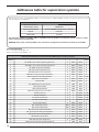
BMS supervisor features: ............................................................................................................ 74
Addresses dedicated to the interface with BMS systems (analog variable) ................................................................ 74
Addresses table for supervision systems ..................................................................................................................... 74
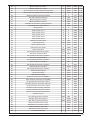
Addresses dedicated to the interface with BMS systems (integer variable) ................................................................ 76
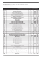
Addresses dedicated to the interface with BMS systems (digital variable) ................................................................. 77
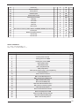
Alarms summary table ................................................................................................................. 81
Alarms log ..................................................................................................................................... 85
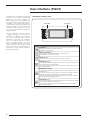
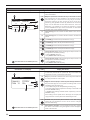
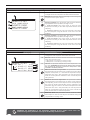
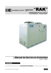
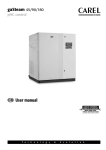
User interface (PGD1)
The WRL unit control panel allows quick
setting of the machine functioning
parameters and their display. All
default settings and any modifications
are memorised in the board. With the
installation of the PGD1 remote panel,
it is possible to repeat all functions and
settings available on the machine from
a distance. After a power cut, the unit
can re-start automatically keeping the
original settings.
The user interface is represented by
a graphical display with six keys for
navigation. The displays are organised
via a menu hierarchy, which can be
activated by pressing the navigation
keys. The display default of these
menus is represented by the main
menu. Navigation through the various
parameters takes place using the arrow
keys positioned on the right of the panel.
These keys are also used to modify the
parameters selected.
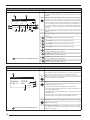
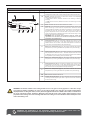
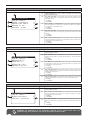
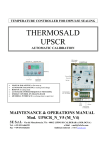
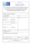
• INTERFACE CONTROL KEYS:
Control keys
Control keys
Prg
Esc
Key
Function
ALARMS key
Displays the list of alarms and the alarms log
(Red LED on = alarm active)
Prg
MENU ACTIVATION key
• Pressing this key activates navigation among the menus;
(Orange LED on = winter mode active)
Esc
MENU EXIT key
• Pressing this key leads to the display of the previous window;
NAVIGATION key (+)
• Pressing this key during navigation through the menus/parameters, allows
to pass to the next menu/parameter;
• Pressing this key during parameter modification, increases the value of the
parameter modified;
NAVIGATION key (enter)
• Pressing this key during navigation through the menus, allows to enter the
selected menu;
• Pressing this key during navigation through the parameters, allows to
select the parameter displayed and enter the modification mode;
• Pressing this key during parameter modification, confirms the modification
to the value of the parameter selected;
NAVIGATION key (-)
• Pressing this key during navigation through the menus/parameters, allows
to pass to the previous menu/parameter;
• Pressing this key during parameter modification, decreases the value of
the parameter modified;
6
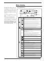
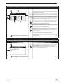
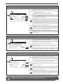
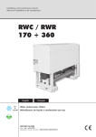
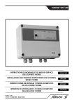
Main display
During normal functioning of the unit,
the PGD1 panel display shows the
standard window. This window contains
the information on the system status
and this information will allow the user
to have a clear indication regarding
functioning of the WRL unit as well as
supply any error and/or malfunctioning
messages.
The information displayed via the main
window is divided into three distinct
parts:
• Upper part of the display (Line 1);
• Central part of the display (Line 2);
• Lower part of the display (Line 3);
Different information can be displayed
in each of these parts, on the basis of
the functioning mode, the current state
of the unit,the user settings etc.
To have a clear interpretation of the
icons present in the main window,
refer to the table at the side.
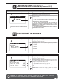
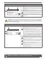
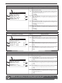
• MAIN WINDOW DISPLAY:
12:14
Fri
o
20.5 C
Sanitary Temp.
Status
On
Line
Icons
A
Line 1
B
Line 2
C
Line 3
o
20.3 C
P
G
Meaning
Indicates that the entire system (chiller, radiant panels, fan coils,
solar kit, DHW) is enabled to function (ON state)
Indicates that the system is set to function in heating mode
A
Indicates that the system is set to function in cooling mode
Indicates that the system envisions management of the DHW
12:14
Fri
B
The time and day are displayed in the right part of the line
Indicates the return temperature from the system
DHW T.
Status:
If DHW management is enabled, the temperature detected inside
the DHW storage tank is displayed.
The state of the system is indicated in the left part of the line. This
state can be:
• ON = system active and functioning;
• OFF = system off;
• Alarm Off = a serious alarm is present that stops the system;
• Super. Off = system supervision has prevented unit start-up;
• Time period Off = the time periods set envision the system Off;
• DigIN Off = The digital input (ID8) is closed, putting the system in OFF;
• Protect = switch-off due to anti-freeze safety activation;
Indicates that the integration system (resistance or boiler) is active.
If the integrative systems start-up simultaneously with any Solar
collectors, only the icon relative to the latter will be displayed.
Indicates that one or more Solar collectors are installed and active
Indicates switch-on of the compressor/s Indicates the switch-on of
the compressor/s (if there are several compressors active, more
icons will be displayed).
C
S
Indicates that the DHW circuit pump is active.
Indicates the activation of the 3-way diverter valve in the systems
with production of DHW, which envision it
S
P
G
FC
Indicates that the system circuit pump is active. If it flashes it
means that the pump functions but the compressor has not yet
started (normal working condition phase).
Indicates that the geothermic/non-returnable water circuit
is active. If it flashes it means that the pump functions but the
compressor has not yet started (normal working condition phase).
Indicates that the freecooling accessory is active
Indicates that the unit is operating in economy mode
P
OFF
Indicates that you implement a preventive action
Indicates that the unit is turned off by time slot
7
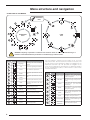
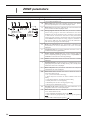
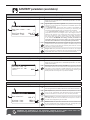
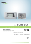
Menu structure and navigation
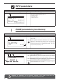
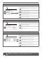
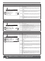
• STRUCTURE OF THE MENUS:
Password
0101
1
2
13
A
H
3
12
B
4
11
ASSISTANCE
Menu
P1
USER
menu
G
C
5
10
F
6
9
D
E
8
!
Index
WARNING: tampering of parameters contained in the assistance menu can cause unit malfunctioning. It is
therefore recommended that these parameters are modified only by authorised staff.
Icon
Menu
Menu function
1
Language
Selecting t he user int er f ace
language
2
Info
Information regarding the software
3
Areas
Areas assistance parameters
4
Chiller
Assistance parameters for the
chiller
5
Domestic hot
water
6
Pumps
7
8
9
8
7
The menu display is organised via the rotation of the icons that
represent the same. Once the desired icon has been selected, enter
the selected menu, thus allowing the display or modification of the
parameters that make it up. The procedure for navigation of the
menus or the modification of the parameters is explained in detail in
the "Use operational procedures", to which reference can be made
for further information.
Index
Icon
Menu
Menu function
A
Inputs outputs
Contains the information
(temperature, pressure, etc.) of the
system components
Assistance parameters for pumps
B
ON/OFF
Switches the unit on and off and
sets its functioning mode (summer/
winter)
Solar
Assistance parameters for solar
integration
C
Areas
Areas work set and time periods
m a n a g e m e n t ( v i a S TA / S T H
accessories)
Timer
Devices working hours timer
D
Chiller
Management of the chiller
paramet er s, s t andar d/ener gy
saving work set-point
E
Domestic hot
water
DHW management parameters(setpoint, consent, temperature, time
periods, etc.)
Definition of system features
F
Clock
Manages all parameters linked to
the system time (hour, date, etc.)
Time periods
Manages programming of the
programs to be actuated during the
time periods
After-sales
assistance
Protects the after-sales assistance
menu with password request
Manual
Assistance parameters for the
DHW
Manual controls forcing
10
Accessories
11
PLANT CONF.
12
Various
Setting assistance parameters
G
13
In/Out
Input and output states
H
Enabling of accessories modules
P1
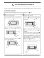
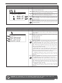
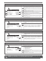
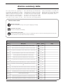
! Use operational procedures
To manage or modify the WRL unit operational parameters, the control board interface on the machine must be used. The
fundamental operations that the user must be able to perform for correct use of the unit are:
(1) To pass from one menu to another;
(2) To select and modify a parameter;
the parameters that can be modified by the set are identified in this manual by the (
1
) icon;
2
To pass from one menu to another
To select and modify a parameter
(a) In order to scroll the various menus (the order with
which the menus are displayed is represented in the
previous page) it is first necessary to enter the menu
selection mode, pressing the ( ) key;
(a) Once the selected menu has been entered (following
the procedure 1 ) it is possible to scroll the windows that
make it up, using the arrow keys, using the ( ) key to pass
to the previous parameter and the( ) key to pass to the
next parameter;
Prg
previous
parameter
(b) Once the menu selection mode has been entered,
these can be scrolled using the arrow keys: the ( ) key to
pass to the previous menu and the ( ) key to pass to the
next menu;
next
parameter
(c) When the desired parameter is displayed, press the (
) key to enter the parameter. To exit the parameter and
go back to parameters selection mode, press the ( ) key;
Esc
previous
memory
next
menu
(c) When the desired menu is displayed, press the ( ) key
to enter the menu. To exit the menu and go back to menu
selection mode, press the ( ) key;
Esc
ATTENTION:
Once a parameter has been selected, press the ( )
key to automatically enter the modification mode of that
parameter. From this mode it is possible to set the desired
values for the parameters, following the procedure below:
(1) by pressing the ( ) key, a flashing cursor will
appear near to the first field that can be modified of the
parameter (if fields that can be modified do not appear, no
cursor will appear);
(2) by pressing the ( ) key or the ( )key the value in the
field will be increased or decreased;
(3) by pressing the ( ) key, the modifications to the field
value will be confirmed, saving in the memory;
On the basis of the type of parameter selected, the
number of fields that can be modified could vary;
To enter
a menu
To exit a
menu
To enter a
parameter
To exit a
parameter
9
! WIZARD guided procedure (Password 0303)
On commissioning, the unit will request a series of basic information from the user, for a first
setting of the operational parameters necessary for the correct functioning of the unit. This
procedure must be carried out by the installer or a person with knowledge of the technical
features of the unit and the system in which it is inserted. WARNING: until the guided procedure
has bee completed, the unit will signal an alarm (code AL102); this alarm will disappear once
the guided procedure has been completed correctly.
COMMISSIONING - Selection of system language
Visualisation on unit display
A
Change language
Index
Display/Parameter
A
Change language: this window is the first to be displayed once
the unit is powered. It can be used to select the language with
which the software strings will be displayed.
B
Language: indicates the language to be set in the unit.
Language:
B
ENGLISH
Display time:
D
030
C
Parameters that can be modified by the user
Time for the choice of language: Indicates the time available
to the installer to select the default language, Once this time
has expired, the language selected will be used as the system
language (it will however be possible to change it via the
relative menu, as indicated in the relative chapter).
COMMISSIONING - Selecting the WIZARD guided procedure
Visualisation on unit display
A
Password insert
0000
Parameters that can be modified by the user
10
B
Index
Display/Parameter
A
Enter password: this parameter allows to insert a specific
password for access to an assistance menu.
B
Password: this icon sets the password for entry to the
WIZARD.
WARNING:
• At the end of the guided procedure, the wizard password
can be customised by the installer, who will keep the new
password for future interventions;
• The user is not enabled to modify and/or manage the
parameters contained in the wizard, as these parameters
could cause damage to the unit if set incoherently with the
features of the unit;
• The default password to allow the installer to access the
menu WIZARD 0303 is in the case after having finished the
wizard, you wanted to run it again, the installer must enter
the password 0303 on the first screen menu HELP (Enter
password protected menu )
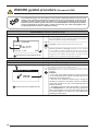
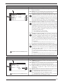
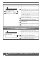
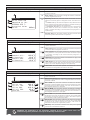
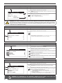
WIZARD Procedure - Setting the DHW circuit
Visualisation on unit display
A
B
BASIC
Wizard
Sanitary type:
NOT PRESENT
Index
Display/Parameter
A
Wizard: the parameters involved in the guided procedure are
set in this window.
B
Basic: this icon indicates that the parameter set in this
window is relative to unit basic settings.
C
Type of DHW: indicates the type of DHW control connected to
the unit installed; this setting could be:
• NOT PRESENT (means that the unit does not envision the
production of DHW);
• TOTAL RECOVERY UNIT (Means that the unit produces
DHW using a total recovery unit mounted on the unit);
• PRIORITY + VALVE (means that the DHW production takes
place by piloting the request via the management of one 3-way
diverter valve. In this case, the DHW production has priority
with respect to system request);
• PRIORITY + PUMP (means that the DHW production takes
place by piloting the request via the management of two
hydraulic pumps. In this case, the DHW production has priority
with respect to system request).
C
Parameters that can be modified by the user
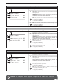
Procedure WIZARD - Set the type of total recovery
Visualisation on unit display
A
B
BASIC
Wizard
Machine purchased
after 1/5/2011?
YES
Index
Display/Parameter
A
Wizard: the parameters involved in the guided procedure are
set in this window.
B
Basic: questa icona indica che il parametro impostato in questa finestra, è relativo alle impostazioni base dell’unità.
C
Date of Purchase Unit: This parameter indicates whether the
unit was purchased after 1/5/2011, as the total recovery
units purchased after this date have a probe mounted in the
heat exchanger.
C
recovery unit
o
45.5 C
Parameters that can be modified by the user
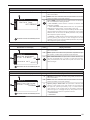
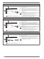
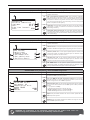
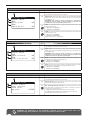
WIZARD procedure - To set the position of the system pump for hydraulic parallel
Visualisation on unit display
A
B
BASIC
Wizard
Position plant pump
winter, side:
INTERNAL
C
Parameters that can be modified by the user
Index
Display/Parameter
A
Wizard: the parameters involved in the guided procedure are
set in this window.
B
Basic: this icon indicates that the parameter set in this
window is relative to unit basic settings.
C
System pump in winter side: this parameter indicates the
position of the system pump with respect to the valves for
the hydraulic parallel (necessary only in models without
cycle reverse on the cooling side); as its position imposes a
particular logic for managing this pump. This position can be,
with respect to the valves for hydraulic inversion:
• DOWNSTREAM;
• UPSTREAM.
11
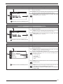
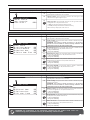
WIZARD procedure - Set the presence of the external air probe
Visualisation on unit display
A
B
OPTION
Wizard
Enable
External air temp.
YES
C
Index
Display/Parameter
A
Wizard: the parameters involved in the guided procedure are
set in this window.
B
Option: this icon indicates that the parameter set in this
window is relative to the settings linked to the accessories
relative to the unit installed.
C
External air temperature presence: this parameter indicates
whether the external air probe accessory has been installed
(KSAE accessory). This setting can be:
• YES (accessory installed);
• NO (accessory not installed);
Parameters that can be modified by the user
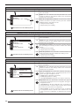
WIZARD procedure- To set the presence of the freecooling kit and solar kit
Visualisation on unit display
A
B
OPTION
Wizard
Enable
freecooling:
NO
C
Enable
solar module:
NO
D
Index
Display/Parameter
A
Wizard: the parameters involved in the guided procedure are
set in this window.
B
Option: this icon indicates that the parameter set in this
window is relative to the settings linked to the accessories
relative to the unit installed.
C
Freecooling kit presence: this parameter indicates whether
the freecooling kit accessory has been installed. This setting
can be:
• YES (accessory installed);
• NO (accessory not installed);
D
Solar kit presence: this parameter indicates whether the
solar kit accessory has been installed. This setting can be:
• YES (accessory installed);
• NO (accessory not installed);
Parameters that can be modified by the user
WIZARD Procedure - Set the system integration
Visualisation on unit display
Index
Display/Parameter
A
Wizard: the parameters involved in the guided procedure are
set in this window.
B
Option: this icon indicates that the parameter set in this
window is relative to the settings linked to the accessories
relative to the unit installed.
C
Type of integration: this parameter indicates the type (if
present) of integration given to the DHW production for the
system. This type of integration can be:
• NONE (system integration not present);
• BOILER (integration from boiler);
• ELECTRIC RESISTANCE (integration from electric resistance).
D
Requested as: this parameter indicates the type of
management regarding the source of integration. This type of
management can be:
• INTEGRATION to HP (the integration logic is signalled, i.e.
management which, in specific cases, envisions the combined
use of heat pumps and source of integration);
•REPLACEMENT at HP (the replacement logic is selected,
i.e. management which, in specific cases, envisions thus use
of just one source of integration in replacement of the heat
pump).
A
B
OPTION
Wizard
Plant integration
Type:
NONE
Required by:
---
C
D
Parameters that can be modified by the user
12
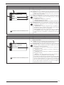
WIZARD Procedure - Set the DHW integration
Visualisation on unit display
Index
Display/Parameter
A
Wizard: the parameters involved in the guided procedure are
set in this window.
B
Option: this icon indicates that the parameter set in this
window is relative to the settings linked to the accessories
relative to the unit installed.
C
Type of integration: this parameter indicates the type (if
present) of integration given to the DHW production. This type
of integration can be:
• NONE (system integration not present);
• BOILER (integration from boiler);
• ELECTRIC RESISTANCE (integration from electric resistance).
D
Requested as: this parameter indicates the type of
management regarding the source of integration. This type of
management can be:
• INTEGRATION to HP (the integration logic is signalled, i.e.
management which, in specific cases, envisions the combined
use of heat pumps and source of integration);
•REPLACEMENT at HP (the replacement logic is selected,
i.e. management which, in specific cases, envisions thus use
of just one source of integration in replacement of the heat
pump).
A
B
OPTION
Wizard
DHW integration
Type:
NONE
Required as:
NONE
C
D
Parameters that can be modified by the user
WIZARD Procedure- To set the type of terminals in heating mode
Visualisation on unit display
A
B
PLANT
Wizard
Ambient control
Heating by:
RADIATOR
C
Parameters that can be modified by the user
Index
Display/Parameter
A
Wizard: the parameters involved in the guided procedure are
set in this window.
B
Plant: this icon indicates that the parameter set in this
window is relative to the settings linked to the system.
C
Heating with: this parameter indicates the type of terminals
used for heating, indicating the device installed, the heating
work set-point is set automatically:
• RADIANT (i.e. the presence of radiant panels is specified for
heating, set at 35°C);
• FANCOILS (i.e. the presence of fancoils is specified for
heating, set at 45°C);
• RADIATORS (i.e. the presence of radiators is specified for
heating, set at 55°C);
• MIXED (i.e. the utility presence whose work set-point in
heating mode is compatible with 45°C is specified);
In the event of mixed system (for examples fancoils plus radiant
panels), the device that requests water at a higher temperature
must be indicated. Moreover, it is necessary to remember that
the fancoil terminals and the radiators cannot be managed
via the STA and STH accessories but must be managed by
dedicated thermostats, which are not supplied.
13
WIZARD Procedure - To set the type of terminals in cooling mode
Visualisation on unit display
A
B
PLANT
Wizard
Ambient control
Cooling by:
WATER, GLICOLE 10%
Index
Display/Parameter
A
Wizard: the parameters involved in the guided procedure are
set in this window.
B
Plant: this icon indicates that the parameter set in this
window is relative to the settings linked to the system.
C
Cooling with: this parameter indicates the type of terminals
used for cooling, indicating the device installed, the cooling
work set-point is set automatically:
• RADIANT (i.e. the presence of radiant panels is specified for
cooling, set at 17°C, evaporator anti-freeze set 4°C);
• FANCOILS (i.e. the presence of fan coils is specified for
cooling, set at 12°C, evaporator anti-freeze set 4°C);
• RADIATORS (i.e. the presence of radiators is specified for
cooling, set at 12°C, evaporator anti-freeze set 4°C);
• 0% GLYCOL WATER (i.e. the presence of cooling devices is
specified for cooling, suitable to function with set-point set at
7°C, evaporator anti-freeze set 4°C);
• 10% GLYCOL WATER (i.e. the presence of cooling devices
is specified for cooling, suitable to function with 10% glycoled
water, set-point set at 7°C, evaporator anti-freeze set -10°C);
• 20% GLYCOL WATER (i.e. the presence of cooling devices
is specified for cooling, suitable to function with 20% glycoled
water, set-point set at 7°C, evaporator anti-freeze set -10°C);
• GLYCOL WATER >20% (i.e. the presence of cooling devices
is specified for cooling, suitable to function at > 20% glycoled
water, set-point set at 7°C, evaporator anti-freeze set -10°C).
C
Parameters that can be modified by the user
WIZARD Procedure - Setting the anti-freeze set on the geothermic side
Visualisation on unit display
Index
Display/Parameter
A
Wizard: the parameters involved in the guided procedure are
set in this window.
B
Plant: this icon indicates that the parameter set in this
window is relative to the settings linked to the system.
C
Glycol percentage: this parameter indicates the percentage
of glycol used in the water in the geothermic circuit. By setting
this percentage the anti-freeze threshold is set automatically
on the geothermic side, suitable:
• 0% (No glycol is inserted in the circuit geothermic; 4°C
geothermic anti-freeze set);
• 10% (Mixture with glycol at 10% in the circuit geothermic;
-1°C geothermic anti-freeze set);
• 20% (Mixture with glycol at 20% in the circuit geothermic;
-10°C geothermic anti-freeze set);
A
B
PLANT
Wizard
Geotermic side
Presenze of glicol
0%
C
Parameters that can be modified by the user
14
WIZARD Procedure - To set the number of areas and rooms
Visualisation on unit display
A
B
PLANT
Wizard
Number of zones
radiant:
Number of rooms
Zone 1:
Zone 2:
Zone 3:
3
1
1
1
Index
Display/Parameter
A
Wizard: the parameters involved in the guided procedure are
set in this window.
B
Plant: this icon indicates that the parameter set in this
window is relative to the settings linked to the system.
C
Number of areas: this parameter indicates the number of
areas managed by the unit electronics. Remember that the
standard unit can manage just one area (also remember
that area 1 can have just one room) and if 2 or 3 areas are
to be managed the VMFCRP accessory must be purchased
and assembled. On the basis of the value specified in this
parameter, some following windows may not be displayed.
D
Number of Area 1 rooms: this parameter indicates the
number of rooms that make up area 1. This area is managed
by the standard unit without necessity of the additional module
(VMFCRP accessory). The feature of this area is that of not
being able to envision more rooms, but can be managed with
the use of a STA or STH accessory thermostat, or without.
To select the type of installation envisioned, the value of the
parameter must be set as:
• 0 (area without room thermostat);
• 1 (area with STA or STH thermostat).
E
Number of Area 2 rooms: this parameter indicates the
number of rooms that make up area 2 (in this case, the
unit cannot manage al loads involved, and it is necessary to
envision a VMFCRP accessory, as well as a STA or STH for
every room supplied with radiant panels); this value can be:
• 0 (the area is served by different terminals to the radiant
panels, therefore this area does not envision the STA/H
accessories);
C
D
E
F
• 1 (the area is served by a radiant panel and is formed by just one room);
• 2 (the area is served by radiant panels and is formed by two rooms);
F
Parameters that can be modified by the user
Area 3: this parameter indicates the number of rooms that
make up area 3 (in this case, the unit cannot manage all loads
involved, and it is necessary to envision a VMFCRP accessory,
as well as a STA or STH for every room supplied with radiant
panels); this value can be:
• 0 (the area is served by different terminals to the radiant
panels, therefore this area does not envision the STA/H
accessories);
• 1 (the area is served by a radiant panel and is formed by just one room);
• 2 (the area is served by radiant panels and is formed by two rooms);
WIZARD procedure - To set area 1 thermostat (if present)
Visualisation on unit display
A
B
PLANT
Wizard
ZONE 1
Device type
Room 1: STA/H
TEMP. ONLY
Index
Display/Parameter
A
Wizard: the parameters involved in the guided procedure are
set in this window.
B
Plant: this icon indicates that the parameter set in this
window is relative to the settings linked to the system.
C
Type of device: this parameter indicates that the room
displayed is supplied with a STA or STH accessory room
thermostat.
D
Room probe: this parameter indicates the type of room
thermostat used. The values that can be set are:
• TEMPERATURE ONLY (indicates that the accessory
thermostat used for the room displayed is a STA);
• TEMPERATURE/HUMIDITY (indicates that the accessory
thermostat for the room displayed is a STH);
C
D
Parameters that can be modified by the user
15
WIZARD procedure - To set area 2 thermostat (if present)
Visualisation on unit display
A
B
PLANT
Wizard
ZONE 2
Device type
Room 1: STA/H
TEMP. ONLY
Index
Display/Parameter
A
Wizard: the parameters involved in the guided procedure are
set in this window.
B
Plant: this icon indicates that the parameter set in this
window is relative to the settings linked to the system.
C
Type of device: this parameter indicates that the room
displayed is supplied with a STA or STH accessory room
thermostat.
D
Room probe: this parameter indicates the type of room
thermostat used. The values that can be set are:
• TEMPERATURE ONLY (indicates that the accessory
thermostat used for the room displayed is a STA);
• TEMPERATURE/HUMIDITY (indicates that the accessory
thermostat for the room displayed is a STH);
C
D
Parameters that can be modified by the user
WIZARD procedure - To set area 3 thermostat (if present)
Visualisation on unit display
A
B
PLANT
Wizard
ZONE 3
Device type
Room 1: STA/H
TEMP. ONLY
Index
Display/Parameter
A
Wizard: the parameters involved in the guided procedure are
set in this window.
B
Plant: this icon indicates that the parameter set in this
window is relative to the settings linked to the system.
C
Type of device: this parameter indicates that the room
displayed is supplied with a STA or STH accessory room
thermostat.
D
Room probe: this parameter indicates the type of room
thermostat used. The values that can be set are:
• TEMPERATURE ONLY (indicates that the accessory
thermostat used for the room displayed is a STA);
• TEMPERATURE/HUMIDITY (indicates that the accessory
thermostat for the room displayed is a STH);
C
D
Parameters that can be modified by the user
WIZARD procedure - To set the label for room 1 (if present)
Visualisation on unit display
A
B
PLANT
Wizard
Room 1 Name
ROOM 1:
C
Parameters that can be modified by the user
16
Index
Display/Parameter
A
Wizard: the parameters involved in the guided procedure are
set in this window.
B
Plant: this icon indicates that the parameter set in this
window is relative to the settings linked to the system.
C
Room name: this parameter allows to change the name
associated to room 1 of area 1;
WIZARD procedure - To set the label for room 2 (if present)
Visualisation on unit display
A
B
PLANT
Wizard
Room 2 Name
ROOM 2:
Index
Display/Parameter
A
Wizard: the parameters involved in the guided procedure are
set in this window.
B
Plant: this icon indicates that the parameter set in this
window is relative to the settings linked to the system.
C
Room name: this parameter allows to change the name
associated to room 1 of area 2;
C
Parameters that can be modified by the user
WIZARD procedure - To set the label for room 3 (if present)
Visualisation on unit display
A
B
PLANT
Wizard
Room 3 Name
ROOM 3:
Index
Display/Parameter
A
Wizard: the parameters involved in the guided procedure are
set in this window.
B
Plant: this icon indicates that the parameter set in this
window is relative to the settings linked to the system.
C
Room name: this parameter allows to change the name
associated to room 1 of area 3;
C
Parameters that can be modified by the user
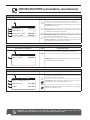
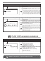
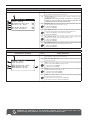
WIZARD Procedure - Setting protocol for BMS
Visualisation on unit display
B
OPTIONS
A
Wizard
BMS
Prot. Communic.:
ModBus RS485
Speed:
Address:
Index
Display/Parameter
A
Wizard: the parameters involved in the guided procedure are
set in this window.
B
Options: this icon indicates that the parameter set in this
window is relative to the optional settings.
C
Type of communication protocol: this parameter indicates
the type of protocol for the communication with BMS system,
this protocol can be:
•--- (no protocol);
•Carel 485;
•ModBus RS485;
•VMF.
D
Speed: this parameter sets the communication speed with
the BMS system.
E
Address: this parameter sets the address with which the unit
is identified regarding the BMS supervision system.
If the chiller is inserted on a VMF system, the address to
assign is: 200
C
19800
D
200
E
Parameters that can be modified by the user
17
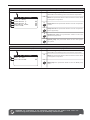
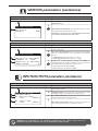
WIZARD Procedure - Customisation of the password for assistance menu
Visualisation on unit display
Index
Display/Parameter
A
Wizard: the parameters involved in the guided procedure are
set in this window.
B
Options: this icon indicates that the parameter set in this
window is relative to the optional settings.
C
Change assistance password: this parameter of fers
the possibility to change the password to the assistance
menu, offering the installer a way of protecting the sensitive
parameters from any unallowed access.
D
Enter old password: if the previous parameter is set
with "YES", this parameter must be set with the current
password value (this control ensures that the setting of the
new password is made by authorised staff). Once entered
correctly, the new password can be inserted.
B
OPTIONS
A
Wizard
Change old password
Service
NO
Insert old service
password
C
D
Parameters that can be modified by the user
WIZARD Procedure - Confirms conclusion of the guided procedure
Visualisation on unit display
A
Wizard
Do you have finish
fast configuration?
NO
B
Parameters that can be modified by the user
18
Index
Display/Parameter
A
Wizard: the parameters involved in the guided procedure are
set in this window.
B
Fast configuration ended: this parameter allows to save
the settings selected during the guided procedure. Once this
parameter is set with "YES", the unit will enter its normal work
phase, working according to the settings specified.
If the guided procedure is to be repeated, select the
ASSISTANCE MENU again and enter password 0303.
WARNING: THE OPERATIONS LINKED TO THE GUIDED
PROCEDURE AND ALL PARAMETERS PROTECTED BY
PASSWORD MUST BE CARRIED OUT BY AUTHORISED
STAFF.
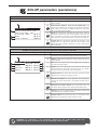
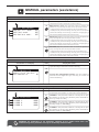
INPUTS/OUTPUTS parameters
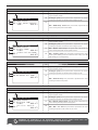
INPUTS/OUTPUTS menu - Information regarding external temperature
Visualisation on unit display
Index
Display/Parameter
A
External air temperature: the data relative to the external
temperature detected via the KSAE external air probe
accessory are displayed in this window. If this accessory is not
present, the window will not be displayed.
B
Minimum night: indicates the minimum value detected by
the external air probe during the night (available if the KSAE
accessory is present).
C
Maximum day: indicates the maximum value detected by
the external air probe during the day (available if the KSAE
accessory is present).
D
External temperature: Indicates the external temperature
currently detected by the external air probe (available if the
KSAE accessory is present).
A
External air temp.
19.9
B
C
o
D
C
o
Min.nigh temp. 07.0 C
Max.day temp. 27.8 o C
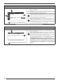
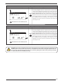
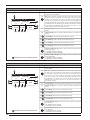
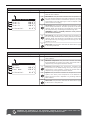
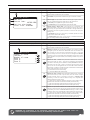
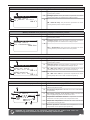
INPUTS/OUTPUTS menu - Heat exchangers input/output temperature
Visualisation on unit display
A
I
Coil
Geot.
B
o
12.5 C
C
15.0 C
D
G
o
Index
Display/Parameter
A
Heat exchanger: this window displays the data relative to the input
and output temperature of the system and geothermic side plate heat
exchangers.
B
Geothermic side heat exchanger output temperature: indicates the
temperature value read in output at the heat exchanger.
C
Geothermic side heat exchanger input temperature: indicates the
temperature value read in entry to the heat exchanger.
D
Geothermic side pump: if the icon is displayed, it indicates that the
geothermic side pump is operating.
E
System side heat exchanger input temperature: indicates the temperature value read in entry to the heat exchanger.
F
Output side heat exchanger input temperature: indicates the temperature value read at outlet of the heat exchanger. If the system
detects the opening of the flow switch, the icon will be displayed.
G
System side pump: if the icon
system side pump is operating.
H-I
Heat exchanger requested power: indicates graphically the power
level requested to the heat exchanger and condenser.
H
Impian.
35.0 C
E
LT
L
o
o
F
P
G
45.0 C
M
Nel caso la valvola sia in tensione, la testa della stessa
diventa nera (nel funzionamento a freddo tale valvola
NON è in tensione, mentre lo è nel funzionamento a
caldo)
F
is displayed, it indicates that the
L
Prevention: Prevention indicates the states of being:
• LT = preventing low temperature output system;
• HT = preventing high temperature in plant output.
M
Frost Resistance: indicates that the antifreeze is active for low temperature.
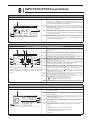
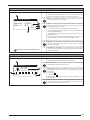
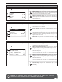
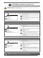
INPUTS/OUTPUTS menu - Compressors work pressure and temperature
Visualisation on unit display
A
Compressors
High 021.5bar
o
T.Disch 080.0
Low 04.3bar
E
Compr. 1 State On
Compr. 2 State On
B
C
Index
Display/Parameter
A
Compressors: this window displays the data relative to the
compressor state.
B
High pressure: indicates the pressure value read in flow to
the compressor.
C
Flow temperature: indicates the temperature value read in
flow to the compressor.
D
Low pressure: indicates the pressure value read in intake at
the compressor.
G
Compressor status: indicates the state of the compressor:
• On,
• Off,
• Min.On (on for minimum functioning time),
• Min.Off (off for minimum switch-off time),
• Manual. (forced switch-on)
• Alarm
D
19
INPUTS/OUTPUTS menu - State of the expansion valve (EEV)
Visualisation on unit display
A
EEV
B
SH 00.0K
C
000%
Evap
Suct
00.0bar
o
00.0 C
o
00.0 C
D
E
F
Index
Display/Parameter
A
EEV: this window displays the data relative to the system
electronic expansion valve.
B
Overheating temperature: indicates the current overheating
temperature.
C
Percentage opening of the electric valve: indicates the
percentage opening value of the electronic valve:
D
Intake pressure at the electronic valve: indicates the
pressure value read at the input to the electronic valve.
E
Intake temperature at the electronic valve: indicates the
temperature value at the input to the electronic valve.
F
Output temperature from the electronic valve: indicates the
temperature value at the output to the electronic valve.
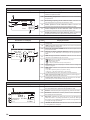
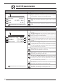
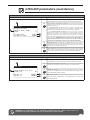
INPUTS/OUTPUTS menu - State of the DHW storage tank
Visualisation on unit display
A
Sanitary tank
Tank
o
44.3 C
Temp.Prod
o
051.0 C
L
C
o
Set 50.0 C
o
Diff 04.0 C
On
D
I
Display/Parameter
A
DHW storage tank: this window displays the data relative to the DHW
storage tank.
B
DHW storage tank temperature: indicates the current temperature
detected inside the storage tank.
C
Set-point for the production of DHW: indicates the value set by the user for
the production of DHW.
D
Domestic hot water production differential: indicates the value set
by the user for the differential on the set-point for the production of
DHW.
E
DHW storage tank electric resistance: indicates that the electric
resistance in the DHW storage tank is active.
F
DHW pump: If the icon indicates the health of the pump:
• S = DHW pump activated;
• OFF = units of time slot;
• LP = the pump is forced to make up for low pressure.
G
Antilegionella: if the icon is displayed, it indicates that the antilegionella
cycle is in progress.
H
DHW status: indicates some particular states relative to the DHW
production:
• On/Alarm (entire system on/system in alarm)
• Off comp. / Off Unit (compressor in off/Unit off)
• Off Board/Off Keyb (unit of from time period/unit off from keyboard)
I
Power required by the health care: this shows the percentage (0% 100%) power required by the health sector.
L
Produced water temperature: indicate the temperature of the water
produced by the unit for domestic hot water circuit.
S
E
H
B
Index
G
F
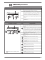
INPUTS/OUTPUTS menu - State of the valve on the geothermic side
Visualisation on unit display
A
Valvola Geo
B
Posizione
C
Pressione 16.9bar
33.0bar
Setpoint
Diff
6.0bar
100 %
D
E
20
Index
Display/Parameter
A
Geothermic valve this window displays data relative to the status of the 2-way valve, placed on the geothermic side.
B
Position: indicates the percentage opening value of the valve:
C
Pressure: indicates the current pressure value detected by
the high pressure transducer.
D
Set-point: indicates the work set point for the geothermic
side; this value is normally expressed in pressure; although
this screen can indicate temperature values if the geothermic
management logic provides it.
E
Geothermic differential: indicates the value set as differential
on the geothermic set-point.
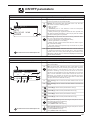
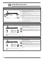
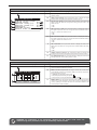
ON/OFF parameters
ON/OFF menu - Unit switch-on/off and settings on the functioning mode
Visualisation on unit display
Index
Display/Parameter
A
Unit On/Off: the data relative to the state of the unit and its
functioning mode are set in this window.
B
System: this parameter sets the state of the unit, The user
can select one of the following states:
• OFF = (unit off);
• ON (unit on);
• ECONOMY (unit on, but selection of the work set-points
reduced due to energy saving mode);
• AUTO (functioning in agreement with the time periods set;
this setting enables the display of the icon (D) and the relative
masks for setting the time periods.
C
Functioning: This parameter sets the functioning mode with which
the unit is made to work; these modes can be:
• Summer (production of refrigerated water)
• Winter (production of hot water);
• DHW only (this mode envisions that the unit works only for
the production of DHW).
• Auto with external temperature (if the external air probe
accessory is present).
D
Time periods active: Indicates that the unit will function
in agreement with the time periods set in the successive
masks of this menu. If the parameter (B) of this window is set
differently to AUTO, this icon will not be displayed and the time
periods will be disabled.
A
B
C
Unit On/Off
System
AUTO
Operation mode
SUMMER
D
Parameters that can be modified by the user
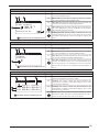
ON/OFF menu - Setting time periods (a) and (b)
Visualisation on unit display
Index
Display/Parameter
A
Unit On/Off: the data relative to time periods (a) and (b) are
set in this window.
B
Day: this parameter indicates the day of the week to which
the programming of time periods (a) and (b) refer. The time
periods setting is memorised for every day of the week,
therefore selecting one day will set the hours of the time
periods (a) and (b) ONLY for the day selected. The remaining
days must be selected and the data entered for each one.
Moreover, it is possible to set the time periods (a) and (b)
for the HOLIDAY action (for further information on the action
concept, refer to the calendar function).
C
Time period (a): This line contains the data relative to the 1st time
period.
D
Time period (b): This line contains the data relative to the 2nd time
period.
A
On/Off Unit
Weekday MONDAY
ON
C
D
a 08:00
OFF
SET C
12:00
Confort
I
Eco
L
b 16:00
22:00
G
H
E
B
o
F
Parameters that can be modified by the user
E
period ON (a): used to set the period switch-on time (a).
F
period OFF (a): used to set the period switch-off time (a).
G
period ON (b): used to set the period switch-on time (b).
H
period OFF (b): used to set the period switch-off time (b).
I
Time period work set (a): used to set the type of set-point for the unit
during execution of the time period (a):
• Confort (NORMAL set-point );
• Eco (ENERGY SAVE mode set-point);
L
Time period work set (b): used to set the type of set-point for the unit
during execution of the time period (b):
• Confort (NORMAL set-point );
• Eco (ENERGY SAVE mode set-point);
21
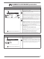
ON/OFF menu - Setting time periods (c) and (d)
Visualisation on unit display
Index
Display/Parameter
A
Unit On/Off: the data relative to time periods (c) and (d) are
set in this window.
B
Day: this parameter indicates the day of the week to which
the programming of time periods (c) and (d) refer. The time
periods setting is memorised for every day of the week,
therefore selecting one day will set the hours of the time
periods (c) and (d) ONLY for the day selected. The remaining
days must be selected and the data entered for each one.
Moreover, it is possible to set the time periods (c) and (d)
for the HOLIDAY action (for further information on the action
concept, refer to the calendar function).
C
Time period (c): This line contains the data relative to the 1st time
period.
D
Time period (d): This line contains the data relative to the 2nd time
period.
A
On/Off Unit
Weekday MONDAY
ON
C
D
c 08:00
B
o
OFF
SET C
12:00
Confort
I
Eco
L
d 16:00
22:00
G
H
E
F
E
period ON (c): used to set the period switch-on time (a).
F
period OFF (c): used to set the period switch-off time (a).
G
period ON (d): used to set the period switch-on time (b).
H
period OFF (d): used to set the period switch-off time (b).
I
Time period work set (c): used to set the type of set-point for the unit
during execution of the time period (c):
• Confort (NORMAL set-point );
• Eco (ENERGY SAVE mode set-point);
L
Time period work set (d): used to set the type of set-point for the unit
during execution of the time period (d):
• Confort (NORMAL set-point );
• Eco (ENERGY SAVE mode set-point);
Parameters that can be modified by the user
ON/OFF menu- Copy time period data function
Visualisation on unit display
Index
Display/Parameter
A
Unit On/Off: in this window it is possible to select the settings
on the time periods set for a particular day of the week and
copy them into one or more days of the week.
B
Day: this parameter indicates from which day of the week the
four time periods are to be copied.
C
Copy in: used to specify in which day the settings selected in
the parameter (B) are to be copied. The settings that can be
supplied for this parameter are:
• An individual day of the week (Monday, Tuesday, etc.);
• ALL (the setting will be copied onto all days of the week and
onto the HOLIDAY action);
• HOLIDAY (the settings selected will be copied only onto the
HOLIDAY action);
If the setting is to be copied onto to two days, for example, the
copy procedure must be performed individually on both.
D
Confirm: this parameter (whose default is the “NO” string)
starts the copy procedure as soon as the value is changed
with the “YES” string.
D
Confirmation message: once the settings have been copied,
the "Done" confirmation string will appear and then disappear
after a few seconds.
A
On/Off Unit
Dayweek
Copy to
FRIDAY
ALL
YES
Done.
B
D
E
C
Parameters that can be modified by the user
22
ON/OFF menu - Setting the calendar function
Visualisation on unit display
A
E
Display/Parameter
A
Calendar: the actions to perform in the calendar function
are set in this window. This function allows to set 5 periods
specifying the duration in days and connecting a specific action
to perform to each of these.
B
Start: Indicates the start date for the 5 periods that can be
set.
C
End: Indicates the end date for the 5 periods that can be set.
D
Action: indicates which actions to perform for one of 5
periods that can be set in the calendar.
E
Time periods start date: these parameters specify the start
date (day/month) for every period. If 00/00 is set as start
and end date, this period results disabled.
F
Time periods end date: these parameters specify the end
date (day/month) for every period. If 00/00 is set as start
and end date, this period results disabled.
G
Actions set for the time periods: these parameters specify
the action to perform in correspondence with the periods set.
The actions can be:
• Off (unit switch-off during the period selected);
• Hol (the settings relative to the time periods specified for
the "HOLIDAY" day will be performed for every day of the
period selected);
• --- (no action).
C
Calendar
B
Index
Start
01/JAN
05/FEB
00/--00/--00/---
End
06/JAN
08/FEB
00/--00/--00/--F
Action
Off
Hol
-------
D
G
Parameters that can be modified by the user
ON/OFF menu- Settings for solar kit management
Visualisation on unit display
A
Solar management
B
Index
Display/Parameter
A
Solar management: solar kit management is enabled in this
window.
B
Solar enabling: this parameter enables the management of
the solar kit. To enable this accessory, it is necessary to set
this parameter with the "YES" string.
Solar On/Off
YES
Parameters that can be modified by the user
23
ZONE parameters
ZONE menu - Display of AREAS parameters
Visualisation on unit display
A
B
C
E
D
1.1 ROOM 1
F
23.5
Humidity:
Actual set:
G
OFF
P
N
24
1 2 3 4 5
o
C
64.3%
020.0 o C
Status:
Disabl.
Index
Display/Parameter
A
Areas index: this parameter indicates to which area the
current data displayed refer.
B
Room index: this parameter indicates to which room (within
the area specified) the current data displayed refers.
C
Room label: this parameter indicates the name with which the
room to which the data displayed refers.
D
Hourly program active for the room: this parameter indicates
which hourly program has been selected for the room
displayed. The hourly programs set a set-point on the basis
of the internal clock and on the basis of the parameters
relative to that program (remember that the time periods
have PRIORITY with respect to hourly programs, therefore if
the unit is in OFF from time period, it cannot be switched on
also if the hourly program should request).
E
Room air temperature: this parameter indicates the
temperature of the air detected in the room currently
displayed.
F
Functioning state: this symbol indicates that the room is
enabled for functioning (ON state).
G
Heating capacity request state: this symbol indicates that the
area is requesting heating capacity to the unit (HEATING or
COOLING on the basis of functioning settings).
H
Season: indicates which season is active for the room currently
displayed.
I
Humidity detected: if the STH accessory is installed in the room
displayed (area panel with humidity sensor), the humidity value
detected in the room is displayed.
L
Room set-point: this parameter indicates the set-point
activated for the room displayed.
M
State of the room: indicates the state in which the room is
found. This state can be:
• On = (room active and functioning);
• Alarm Off (room off due to an alarm relative to the room
itself);
• Unit. Off (the system unit sets the areas in OFF);
• Disabl. (the room is not configured);
• Off Board (room off from hourly programming);
• Off key (room switched off by user).
N
Humidity of the room: indicates that dehumidification is in
progress in the room currently displayed.
O
Room state icon: this icon indicates the current state of the
room. These states can be:
• Room disabled, indicated by the symbol ( OFF );
• Room OFF hourly programming , indicated by the symbol (
);
• Room ON, indicated by the symbol (
).
H
I
L
M
O
ZONE menu - Setting AREA set-point
Visualisation on unit display
A
B
C
1.1 ROOM 1
Index
Display/Parameter
A
Areas index: this parameter indicates to which area the
current data displayed refer.
B
Room index: this parameter indicates to which room (within
the area specified) the data displayed refers.
C
Room label: this parameter indicates the name with which the
room to which the data currently displayed refers.
D
Room set-point: this parameter indicates the work set-point for
the room displayed. Any manual modification of the set-point
will be zeroed at program change.
E
Enabling the room: this flag enables or disables the room not
instantly switching the room on but making the same active
according to the settings of the hourly program linked to the
same.
Actual setpoint
20.5
D
o
C
E
Room switch On:
Parameters that can be modified by the user
ZONE menu - Setting the program time linked to the area
Visualisation on unit display
A
B
Index
Display/Parameter
A
Areas index: this parameter indicates to which area the
current data displayed refer.
B
Room index: this parameter indicates to which room (within
the area specified) the current data displayed refers.
C
Room label: this parameter indicates the name with which the
room to which the data currently displayed refers.
D
Area time program: this parameter indicates which hourly
program to associate to the room currently selected. Up to
five hourly programs are available (can be set in the clock
menu) each of which can be selected and associated to a
room.
C
1.1 ROOM 1
Timezone
selection
2
D
Parameters that can be modified by the user
ZONE menu - Setting the area dehumidification set-points
Visualisation on unit display
A
B
C
Dehumidifer
Comfort
D
E
Index
Display/Parameter
A
Dehumidifier: this parameter indicates the dehumidification
values to be adopted in the various modes.
B
Comfort: this column states the dehumidification set
(expressed as a relative humidity percentage) to use if active
in the comfort mode area.
C
Economy: this column states the dehumidification set
(expressed as a relative humidity percentage) to use if active
in the economy mode area.
D-E
Zones: every line represents the dehumidification sets in
the various modes, the area are distinguished by the code =
Z:area number for every area active in the system.
Economy
Z:01 050.0%rH 050.0%rH
Z:02 050.0%rH 050.0%rH
Parameters that can be modified by the user
25
ZONE menu - Setting the area dehumidification set-points
Visualisation on unit display
A
Umidifier
Setpoint:
Index
Display/Parameter
A
Humidifier: this parameter indicates what is the humidity
value to reach.
B
Set-point: this parameter indicates what is the humidity value
to reach in the areas where humidity control is active.
B
050.0%rH
Parameters that can be modified by the use
ZONE menu - Information regarding the state of the areas
Visualisation on unit display
Index
Display/Parameter
A
Area 1: this parameter indicates to which area the data
displayed refer. If several areas are present, this window will
be repeated for all areas installed.
B
Water: this parameter indicates the temperature of the area
inlet water (measured after the mixing valve).
C
Set: this parameter indicates the set-point active for the area
displayed. If the climatic curve function has been activated
(function that can be activated in the AREAS (assistance)
menu), this set may not maintain a fixed value, but continue to
vary (on the basis of that calculated by the regulation).
D
Diff: this parameter indicates the differential applied to the
area set-point.
E
Valv.: this parameter indicates the opening percentage of the
mixing valve on the circuit displayed.
F
Pump: if this icon is displayed, it indicates that the pump of the
area indicated is active.
G
State: this parameter indicates what is the status of the area
displayed; this status can be:
•On (area active);
•Alarm (alarm active on the area);
• Disabl. (area disabled);
•Rooms Off (area not active);
•Off Rem (unit off from remote control);
•Unit Off.
A
Zone 1
o
Water 28.5 C
o
P
On
G
26
F
Set
29.6 C
o
Diff 04.0 C
Valv.
077%
B
C
D
E
ZONE menu - Setting cooling AREA set-point
Visualisation on unit display
A
Zone 1
Valve 1
Water setpoint:
❄
18.0
o
C
Index
Display/Parameter
A
Areas index: this parameter indicates to which area the data
currently displayed refers. If several areas are set, several
masks will be displayed successively, each of which will have a
number that indicates to which area reference is being made.
B
Water set-point valve: this value represents the cooling work
set-point for the area to which reference is made; ATTENTION:
if the cooling climatic curve function is active (can be activated
from AREA parameters (installer)), this window will not be
displayed as the work set will be calculated automatically and
not set by the user.
B
Parameters that can be modified by the use
ZONE menu - Setting heating AREA set-point
Visualisation on unit display
A
Zone 1
Valve 1
Water setpoint:
❊
35.0
o
C
B
Index
Display/Parameter
A
Areas index: this parameter indicates to which area the data
currently displayed refers. If several areas are set, several
masks will be displayed successively, each of which will have a
number that indicates to which area reference is being made.
B
Water set-point valve: this value represents the heating work
set-point for the area to which reference is made; ATTENTION:
if the heating climatic curve function is active (can be activated
from AREA parameters (installer)), this window will not be
displayed as the work set will be calculated automatically and
not set by the user.
Parameters that can be modified by the use
!
WARNING: the number of windows present in this menu depends on the number of areas (and rooms) set in the
installer system. If several areas are present (or an individual area with several rooms),the windows shown for
the areas menu, will be shown again for every room, obviously updating their indexes and the labels permanently
in a way to allow the user to identify them easily.
27
CHILLER parameters
CHILLER menu- System set-point display
Visualisation on unit display
A
Plant setpoint
B
C
15.0
Diff
o
Index
Display/Parameter
A
System set point: this window displays the main information
regarding the current chiller settings.
B
Active set-point: this parameter indicates the set value with
which the unit is working.
C
Differential: this parameter indicates the differential value applied to
the regulation of the work set point.
D
Season: this parameter indicates in which functioning mode the unit
is set.
E
Request: Indicates that the distance of the system
temperature, with respect to the work set-point; plus the
value of this value approaches 100%. The further away from
the set work set (therefore in the event of a unit with just
one compressor, when this percentage reaches 100% the
compressor will activate).
D
C
03.0 o C
Require
100%
E
CHILLER menu- Setting system NOMINAL set-point
Visualisation on unit display
A
Unit thermoreg.
Comfort setpoints
Water
o
038.0 C
012.0 C
o
B
Index
Display/Parameter
A
Unit heat regulation: the work nominal set-point values are
displayed in this window.
B
Water set-point in heating mode: this parameter indicates
the set value with which the unit will work when heating.
C
Water set-point in cooling mode: this parameter indicates
the set value with which the unit will work when cooling.
C
Parameters that can be modified by the user
CHILLER menu- Setting system ECONOMY set-point display
Visualisation on unit display
A
Unit Thermoreg.
Economy setpoint
Water
o
038.0 C
012.0 C
o
B
C
Parameters that can be modified by the user
28
Index
Display/Parameter
A
Unit heat regulation: the work economy set-point values are
displayed in this window.
B
Water set-point in heating mode: this parameter indicates
the set value with which the unit will work when heating, when
the energy saving mode is active.
C
Water set-point in cooling mode: this parameter indicates
the set value with which the unit will work when cooling, when
the energy saving mode is active. Functioning in Economy
mode can be activated from the ON/OFF mask and time
period.
DOMESTIC HOT WATER parameters
DOMESTIC HOT WATER menu - Main settings for DHW production
Visualisation on unit display
A
Index
Display/Parameter
A
Domestic hot water: this window displays the main settings
for the production of DHW.
B
Set-point: this parameter indicates the temperature value
with which the DHW will be produced.
C
Request: Indicates that the distance of the temperature inside
the DHW storage tank, with respect to the work set-point;
plus the value of this value approaches 100%. The further
away from the set work set (therefore in the event of a unit
with just one compressor, when this percentage reaches
100% the compressor will activate).
D
Enable: this flag sets the activation of the production of DHW.
E
DHW electric resistance: if this icon flashes, it means that the
integrative electric resistance is functioning inside the DHW storage
tank. This resistance could have been activated manually or startedup as integration to the unit or for anti-legionella cycle.
F
DHW status: Indicates the state of the production of DHW;
this state can be:
• On (DHW function active and ready for use);
• Alarm (an alarm relative to DHW is present);
• Off Comp. (DHW production blocked due to compressor
switch-off);
• Off unit. (DHW production switched-off from the system);
• Fasce Off (DHW production off from time period);
• Off key (DHW production switched off by user).
• Manual (DHW production requested by digital input).
Sanitary water
Setpoint
50.0
B
C
require
D
Enable
o
C
E
000%
Unit Off
F
Parameters that can be modified by the user
DOMESTIC HOT WATER menu - Enabling time periods for DHW production
Visualisation on unit display
A
Sanitary water
Timezone
selection
B
YES
Index
Display/Parameter
A
Domestic hot water: the time periods for the production of
DHW are enabled in this window.
B
Time periods: this parameter indicates whether to enable the
time periods or not for the production of DHW. If they have
been enabled, the successive windows will take the settings
for the weekly time periods similarly to those relative to
functioning of the unit specified in the ON/OFF menu.
Parameters that can be modified by the user
29
DHW menu - Setting time periods (a) and (b)
Visualisation on unit display
Index
Display/Parameter
A
Domestic hot water: the data relative to time periods (a) and
(b) are set in this window.
B
Day: this parameter indicates the day of the week to which the
programming of time periods (a) and (b) refer. The time periods
setting is memorised for every day of the week, therefore selecting
one day will set the hours of the time periods (a) and (b) ONLY for
the day selected. The remaining days must be selected and the data
entered for each one. Moreover, it is possible to set the time periods
(a) and (b)for the HOLIDAY action (for further information on the
action concept, refer to the calendar function).
C
Time period (a): This line contains the data relative to the 1st time
period.
D
Time period (b): This line contains the data relative to the 2nd time
period.
A
Sanitary water
weekday MONDAY
ON
C
D
a 08:00
OFF
SET C
12:00
ON
I
OFF
L
b 16:00
22:00
G
H
E
B
o
F
E
period ON (a): used to set the period switch-on time (a).
F
period OFF (a): used to set the period switch-off time (a).
G
period ON (b): used to set the period switch-on time (b).
H
period OFF (b): used to set the period switch-off time (b).
I
Time period work set (a): used to set the control to perform during
the time period (a):
• On (DHW production enabled);
• OFF (DHW production disabled);
L
Time period work set (b): used to set the control to perform during
the time period (b):
• On (DHW production enabled);
• OFF (DHW production disabled);
Parameters that can be modified by the user
DHW menu - Setting time periods (c) and (d)
Visualisation on unit display
Index
Display/Parameter
A
Domestic hot water: the data relative to time periods (a) and (b) are set
in this window.
B
Day: this parameter indicates the day of the week to which the
programming of time periods (a) and (b) refer. The time periods setting
is memorised for every day of the week, therefore selecting one day will
set the hours of the time periods (a) and (b) ONLfor the day selected.
The remaining days must be selected and the data entered for each
one. Moreover, it is possible to set the time periods (a) and (b)for the
HOLIDAY action (for further information on the action concept, refer to
the calendar function).
C
Time period (c): This line contains the data relative to the 1st time period.
D
Time period (d): This line contains the data relative to the 2nd time
period.
A
Sanitary water
weekday MONDAY
ON
C
D
c 08:00
OFF
SET C
12:00
ON
I
OFF
L
d 16:00
22:00
G
H
E
B
o
F
Parameters that can be modified by the user
30
E
period ON (c): used to set the period switch-on time (a).
F
period OFF (d): used to set the period switch-off time (a).
G
period ON (c): used to set the period switch-on time (b).
H
period OFF (d): used to set the period switch-off time (b).
I
Time period work set (c): used to set the control to perform during the
time period (c):
• On (DHW production enabled);
• OFF (DHW production disabled);
L
Time period work set (d): used to set the control to perform during the
time period (d):
• On (DHW production enabled);
• OFF (DHW production disabled);
DOMESTIC HOT WATER menu- Copy time period data function.
Visualisation on unit display
Index
Display/Parameter
A
Domestic hot water: in this window it is possible to select the
settings on the time periods set for a particular day of the
week and copy them into one or more days of the week.
B
Day: this parameter indicates from which day of the week the
four time periods are to be copied.
C
Copy in: used to specify in which day the settings selected in
the parameter (B) are to be copied. The settings that can be
supplied for this parameter are:
• An individual day of the week (Monday, Tuesday, etc.);
• ALL (the setting will be copied onto all days of the week and
onto the HOLIDAY action);
• HOLIDAY (the settings selected will be copied only onto the
HOLIDAY action);
If the setting is to be copied onto to two days, for example, the
copy procedure must be performed individually on both.
D
Confirm: this parameter (whose default is the “NO” string)
starts the copy procedure as soon as the value is changed
with the “YES” string.
D
Confirmation message: once the settings have been copied,
the "Done" confirmation string will appear and then disappear
after a few seconds.
A
Sanitary water
Weekday
Copy to
FRIDAY
ALL
YES
Done.
B
D
E
C
Parameters that can be modified by the user
DOMESTIC HOT WATER menu- Copy time period data function.
Visualisation on unit display
A
Index
Display/Parameter
A
Anti-legionella: in this window it is possible to set the execution
of the anti-legionella cycle (whenever necessary).
B
Execution time: this parameter indicates at what time the
anti-legionella cycle will be performed:
C
Execution day: these flags represent the day/days in which the
anti-legionella cycle is to be performed. These flags can have
two states:
• selected ( );
• not selected ( );
Naturally the anti-legionella cycle will only be performed in the
selected days.
D
Enabling: this parameter indicates the activation of the antilegionella cycle. The function will ONLY be performed if this
parameter is set with the "YES" value.
Antilegionella
B
03:00
Mon
Tue
Wed Thur Fri
Sat Sun
C
Enable:
YES
D
31
CLOCK parameters
CLOCK menu - Setting system clock
Visualisation on unit display
Index
A
A
Clock: the system clock settings are displayed in this window.
B
Day: this parameter indicates the day of the week displayed
automatically on the basis of the calendar settings.
Clock
B
Weekday:
C
Date:
15 SEPT. 2010
D
Time:
14:38
Monday
Display/Parameter
C
D
Parameters that can be modified by the user
Date: this parameter indicates the system date set by the
user.
Hour: this parameter indicates the system time set by the
user.
CLOCK menu - Setting day-light saving time
Visualisation on unit display
A
Index
Display/Parameter
A
Clock: the day-light saving time settings are displayed in this
window.
B
Day-light saving time: this parameter indicates whether to
enable the adjustment of the system clock on the basis of the
date, according to successive settings.
C
Transition time: this parameter indicates how much to
increase or decrease (basically it is the start or end of the daylight saving period) the system time on the basis of the time
change.
D
Start of use of day-light saving time: this parameter indicates
on which day of the month to start to use day-light saving time.
To specify it, two parts of the same parameter must be set.
The first indicates the week (first, second, third or last), the
second indicates the day of the week.
Clock
B
D
E
G
H
DST:
ENABLE
Transition time: 060min
Start:
LAST SUNDAY
In MARCH
at 03.00
End:
LAST SUNDAY
In OCTOBER
at 03.00
C
F
I
E
F
G
H
Parameters that can be modified by the user
32
I
Start month: this parameter indicates the month when the
day-light saving time settings must be used
Start hour: this parameter indicates the hour when the daylight saving time settings must be used
End of use of day-light saving time: this parameter indicates
on which day of the month to stop using day-light saving time.
To specify it, two parts of the same parameter must be set.
The first indicates the week (first, second, third or last), the
second indicates the day of the week.
End month: this parameter indicates the month when the daylight saving time settings must no longer be used
End hour: this parameter indicates the hour when the daylight saving time settings must no longer be used
P1
TIMEZONE parameters
TIMEZONE parameters - Selecting the hourly programming to set
Visualisation on unit display
Index
Display/Parameter
A
Selected program: this parameter indicates which hourly
programming has been selected for the setting.
B
Hourly programming icon: this icon graphically represents
the current hourly program selected. The navigation of the
5 programs available is similar to the type of user menu,
therefore can be managed via a graphical menu where the
icons rotate on the basis of the arrow keys pressed.
A
Select
Timezone 1
P1
C
P2
P1
P5
P1
D
B
D
C
Next icon: this icon represents the program after that
selected.
Previous icon: this icon represents the program previous to
that selected.
TIMEZONE menu - Setting the time periods (a) and (b) for the selected hourly programming
Visualisation on unit display
A
Index
Display/Parameter
A
Hourly programming: the data relative to time periods (a)
and (b) for the selected hourly programming are set in this
window.
B
Day: this parameter indicates the day of the week to which the
programming of time periods (a) and (b) refer. The time periods
setting is memorised for every day of the week, therefore selecting
one day will set the hours of the time periods (a) and (b) ONLY for
the day selected. The remaining days must be selected and the data
entered for each one. Moreover, it is possible to set the time periods
(a) and (b)for the HOLIDAY action (for further information on the
action concept, refer to the calendar function).
C
Time period (a): This line contains the data relative to the 1st time
period.
D
Time period (b): This line contains the data relative to the 2nd time
period.
B
Timezone 1
Weekday
ON
o
OFF
SET C
20.0
22.0
20.0
22.0
C
a 08:00
12:00
D
b 16:00
22:00
G
H
E
P1
P1
MONDAY
F
I
L
M
N
E
period ON (a): used to set the period switch-on time (a).
F
period OFF (a): used to set the period switch-off time (a).
G
period ON (b): used to set the period switch-on time (b).
H
period OFF (b): used to set the period switch-off time (b).
I
L
M
Parameters that can be modified by the user
N
COOLING time period work set (a): used to set the work set-point (in
cooling mode)during the time period (a).
HEATING time period work set (a): used to set the work set-point (in
heating mode)during the time period (a).
HEATING time period work set (b): used to set the work set-point (in
cooling mode)during the time period (b).
HEATING time period work set (b): used to set the work set-point (in
heating mode)during the time period (b).
33
TIMEZONE menu - Setting the time periods (c) and (d) for the selected hourly programming
Visualisation on unit display
A
Index
Display/Parameter
A
Hourly programming: the data relative to time periods (c)
and (d) for the selected hourly programming are set in this
window.
B
Day: this parameter indicates the day of the week to which the
programming of time periods (c) and (d) refer. The time periods
setting is memorised for every day of the week, therefore selecting
one day will set the hours of the time periods (c) and (d) ONLY they
must be selected and the data entered for each one. Moreover, it
is possible to set the time periods (c) and (d)for the HOLIDAY action
(for further information on the action concept, refer to the calendar
function).
C
Time period (c): This line contains the data relative to the 1st time
period.
D
Time period (d): This line contains the data relative to the 2nd time
period.
B
Timezone 1
Weekday
ON
o
OFF
SET C
20.0
22.0
20.0
22.0
C
c 08:00
12:00
D
d 16:00
22:00
G
H
E
P1
P1
MONDAY
F
I
L
M
N
Parameters that can be modified by the user
E
period ON (c): used to set the period switch-on time (c).
F
period OFF (c): used to set the period switch-off time (c).
G
period ON (d): used to set the period switch-on time (d).
H
period OFF (d): used to set the period switch-off time (d).
I
COOLING time period work set (c): used to set the work set-point (in
cooling mode)during the time period (c).
L
HEATING time period work set (c): used to set the work set-point (in
heating mode)during the time period (c).
M
COOLING time period work set (d): used to set the work set-point (in
cooling mode)during the time period (d).
N
HEATING time period work set (d): used to set the work set-point (in
heating mode)during the time period (d).
TIMEZONE menu- Copy time period data function
Visualisation on unit display
Index
Display/Parameter
A
Hourly programming: in this window it is possible to select
the settings on the time periods set for a particular day of the
week and copy them into one or more days of the week.
B
Day: this parameter indicates from which day of the week the
four time periods are to be copied.
C
Copy in: used to specify in which day the settings selected in
the parameter (B) are to be copied. The settings that can be
supplied for this parameter are:
• An individual day of the week (Monday, Tuesday, etc.);
• ALL (the setting will be copied onto all days of the week and
onto the HOLIDAY action);
• HOLIDAY (the settings selected will be copied only onto the
HOLIDAY action);
If the setting is to be copied onto to two days, for example, the
copy procedure must be performed individually on both.
D
Confirm: this parameter (whose default is the “NO” string)
starts the copy procedure as soon as the value is changed
with the “YES” string.
D
Confirmation message: once the settings have been copied,
the "Done" confirmation string will appear and then disappear
after a few seconds.
A
Timezone 1
Weekday
Copy to
FRIDAY
ALL
YES
Done.
B
D
E
C
Parameters that can be modified by the user
34
ASSISTANCE Parameters (Password 0101)
ASSISTANCE menu - Introduction of the password for protected menus
Visualisation on unit display
A
Password insert
0000
Index
Display/Parameter
A
Enter password: this parameter allows to insert a specific
password for access to an assistance menu.
B
Password: this icon sets the password for entry to the
assistance menu.
WARNING:
• At the end of the guided procedure, the assistance menu
password can be customised by the installer, who will keep the
new password for future interventions;
• The user is not enabled to modify and/or manage the
parameters contained in the assistance menu, as these
parameters could cause damage to the unit if set incoherently
with the features of the unit;
• The standard password that allows the installer to access
the assistance menu is 0101.
B
Parameters that can be modified by the user
LANGUAGE parameters
LANGUAGE menu - Setting the system language
Visualisation on unit display
A
Change lang.
Index
Display/Parameter
A
Change language: this menu allows to set the parameters
linked to the system language.
B
Language: this icon sets the system language; it is possible to
select from:
• ITALIAN;
• ENGLISH;
• FRENCH;
•GERMAN.
Language:
ENGLISH
B
LANGUAGE menu - Setting language requested on voltage re-application
Visualisation on unit display
A
Change lang.
Enabling
selection mask
start-up lang.:
Display time:
YES
B
030s
C
Index
Display/Parameter
A
Change language: this menu allows to set the parameters
linked to the system language.
B
Enabling language select on start-up: this parameter allows
to enable or disable the language selection window every time
voltage is re-applied. The setting can be:
• YES (disables language select on start-up);
• NO (maintains the choice of language at every voltage startup).
C
Display time: this parameter allows to set the time available
to the user to select the system language.
WARNING: the modification of the parameters identified by this symbol could cause unit
malfunctioning; these parameters can only be modified by authorised staff.
35
INFO parameters
INFO menu - Display of information regarding unit
Visualisation on unit display
A
Index
Display/Parameter
A
Information: this screen displays some construction
information regarding the unit such as:
• Machine model;
• Inspection date;
• Software version.
Aermec
ooo
oo
WRL025 BP M
Ver.: 2.0
01/06/11
Factory tested
11:02 11/02/11
ZONE parameters (assistance)
ZONE menu (assistance) - Setting differential for rooms activation request
Visualisation on unit display
A
Zone
Differential
for activation
request of the
room:
o
2.0 C
Index
Display/Parameter
A
Zones: this menu allows to set the parameters linked to
the management of the areas or their setting at after-sales
service level.
B
Areas request activation differential: this parameter
specifies the differential (with respect to the air temperature
detected in the room by the sensor on the STA/STH
accessory) with which it is established whether the room
requires heating capacity or not.
B
ZONE menu (assistance) - To set the label for room 1 (if present)
Visualisation on unit display
A
B
C
1.1 ROOM 1
Room Name:
D
ROOM 1:
Index
Display/Parameter
A
Areas index: this parameter indicates to which area the
current data displayed refer.
B
Room index: this parameter indicates to which room (within
the area specified) the current data displayed refers.
C
Room label: this parameter indicates the name with which the
room to which the data currently displayed refers.
D
Room name: with this parameter it is possible to set the
name associated to room 1 of area 1;
WARNING: the modification of the parameters identified by this symbol could cause unit
malfunctioning; these parameters can only be modified by authorised staff.
36
ZONE menu (assistance) - To set the work set for room 1 (if present)
Visualisation on unit display
A
B
Index
Display/Parameter
A
Areas index: this parameter indicates to which area the
current data displayed refer.
B
Room index: this parameter indicates to which room (within
the area specified) the current data displayed refers.
C
Room label: this parameter indicates the name with which the
room to which the data currently displayed refers.
D
Winter set-point: this parameter sets the temperature that
is to be reached in the room (air temperature) during winter
functioning mode.
E
Summer set-point: this parameter sets the temperature that
is to be reached in the room (air temperature) during summer
functioning mode.
C
1.1 ROOM 1
Setpoint default
o
022.0 C
020.0 C
o
D
E
ZONE menu (assistance) - To set cooling and heating regulations for room 1 (if present)
Visualisation on unit display
Index
Display/Parameter
A
Areas: this menu allows to set the parameters linked to
the management of the areas or their setting at after-sales
service level.
Zone
B
Valve 1
Cold regulation
FIXED SET-POINT
Heat regulation
CLIMATIC CURVE
Valve: this parameter indicates to which mixing valve
reference is being made:
• Valve 1 (Area 1);
• Valve 2 (Area 2);
• Valve 3 (Area 3).
C
Cooling regulation: this parameter sets the thermostating
logic applied to the mixing valve displayed, this logic can be:
• FIXED SET-POINT this logic tends to take the flow
temperature directly to the value expressed with the work setpoint. Naturally this implies that the area mixer valve remains
open until the STA/STH accessory thermostat signals that
the set-point has been reached);
• DEW POINT (this logic automatically calculates the work
set-point and uses a safety threshold set by the installer, to
prevent the safety panels cooling the floor over the dew point,
thus preventing the formation of water on the floor);
• CLIMATIC CURVE (this logic automatically calculates
the work set-point using the climatic curve set in the next
windows).
D
Heating regulation: this parameter sets the thermostating
logic applied to the mixing valve displayed, this logic can be:
• FIXED SET-POINT this logic tends to take the flow
temperature directly to the value expressed with the work setpoint. Naturally this implies that the area mixer valve remains
open until the STA/STH accessory thermostat signals that
the set-point has been reached);
• CLIMATIC CURVE (this logic automatically calculates
the work set-point using the climatic curve set in the next
windows).
A
B
C
D
WARNING: the modification of the parameters identified by this symbol could cause unit
malfunctioning; these parameters can only be modified by authorised staff.
37
ZONE menu (assistance) - To set the heating climatic curve for area 1 mixing valve (if present)
Visualisation on unit display
A
B
Index
Display/Parameter
A
Areas: this menu allows to set the parameters linked to the
management of the areas or their setting at after-sales service level.
B
Season: indicates the season to which the climatic curve displayed
refers. This parameter can be:
• WIN (winter season, therefore climatic curve referring to heating
function);
• SUM (summer season, therefore climatic curve referring to cooling
function);
C
Valve: indicates the area to which reference is made.
D
Flow set: this parameter indicates the temperatures of the flow
water referring to the external temperatures indicated. These
correspondences between flow water temperature and external air
temperature form the climatic curve. This climatic curve allows a
dynamic adjustment of the area flow water set (area flow water set
means the temperature yielded by the mixer valve of this area) on the
basis of the external air temperature.
WARNING: the minimum and maximum flow set limits will
represent the minimum and maximum temperature limits
reachable in the specified area.
E
Flow temperature (1): this parameter indicates the maximum flow
temperature limit for area 1. This flow temperature will be set as
effective set for the mix valve, if the external temperature is less than
or the same as that specified in the parameter (F).
F
External air temperature (1): this parameter indicates the external
temperature up to using the work set specified in the parameter (E).
G
Flow temperature (2): this parameter indicates the intermediate
flow temperature value for area 1. This flow temperature will be set
as effective set for the mix valve, if the external temperature between
that specified in parameter (F) and in parameter (H).
H
External air temperature (2): this parameter indicates the external
temperature up to using the work set specified in the parameter (G).
I
Flow temperature (3): this parameter indicates the minimum flow
temperature limit for area 1. This flow temperature will be set as
effective set for the mix valve, if the external temperature is greater
than or the same as that specified in the parameter (L).
L
External air temperature (3): this parameter indicates the external
temperature up to using the work set specified in the parameter (I).
M
Ext: label that indicates external air.
N
Instant flow temperature: this value indicates the flow temperature
currently used as set-point (this value is dynamic and varies according
to the climatic curve).
Zone
C
Valve 1
D
Deliv. set >
G
E
I
!
WIN
o
35.0 C
35.0
30.0
28.0
Ext
00.0
15.0
F
H
N
o
20.0 C
L
M
WARNING: the window relative to the cooling climatic curve is not given as it only appears if it has been set (to
set cooling and heating regulations for room 1). If the cooling climatic curve has been set, another window will be
displayed similar to that given above, but the parameter (B) will indicate the “SUM” season label, to indicate that
the curve represents summer functioning. Moreover, note that the trend of the graphics will be specular to that
proposed for the heating curve even if the logic with which the cooling curve must be filled in will be exactly the same
used in the heating curve.
WARNING: the modification of the parameters identified by this symbol could cause unit
malfunctioning; these parameters can only be modified by authorised staff.
38
ZONE menu (assistance) - To set the cooling dew point for area 1 mixing valve (if present)
Visualisation on unit display
A
B
Zone
C
Valve 1
SUM
Anti-condensate function
temperature offset
mixed circuit
o
01.5 C
in summer mode:
Active set.:
!
o
01.5 C
Index
Display/Parameter
A
Areas: this menu allows to set the parameters linked to the
management of the areas or their setting at after-sales service level.
B
Season: indicates the season to which the dew point function refers
for functioning in cooling mode. Naturally, this function is only available
in cooling mode.
C
Valve: indicates the area to which reference is made.
D
Anti-condensate function: this parameter indicates the safety
threshold to add to the dew temperature calculated automatically by
the unit. This value ensures that the temperature of the floor is high
enough to prevent the formation of water on the floor surface.
D
E
E
Active set-point: this value indicates the current work set for the "dew
point" mode.
WARNING: the number of windows present in this menu depends on the number of areas set in the installer system.
If several areas are present (therefore more mixer valves), the windows shown up to now for the AREAS menu
(assistance), will be shown again for every room, obviously updating their indexes and the labels permanently in a way
to allow the user to identify them easily.
ZONE menu (assistance) - To set the 3-way valve management logic.
Visualisation on unit display
A
Index
Display/Parameter
A
Areas: this menu allows to set the parameters linked to the
management of the areas or their setting at after-sales service level.
B
System 3-way valve: this parameter sets the type of logic to use to
manage the area valves; the possible controls are:
• P (PROPORTIONAL control; this logic is based on the addition of
a differential on the mixing set-point, increasing or decreasing the
temperature threshold with which unit power will be requested;
• P+I (PROPORTIONAL+INTEGRAL control; this logic joins the
proportional control to the integral control. The integral control is
based on the insertion of an integral time after which the machine
will have supplied the power requested by the system. Therefore,
the integral time becomes the time in which the power request is
to be satisfied. ATTENTION: the setting of these parameters is
particularly delicate as incorrect values can cause functioning
anomalies. The modifications must only be made by skilled staff.
C
Proportional band: this parameter indicates the value to be used as
proportional band. This band will be applied at the mixing set-point and
allows to increase or decrease the sensitivity with which the unit will
intervene to maintain the work set.
D
Integral time: this parameter indicates the duration of the integral
time, i.e. of the time in which the unit must satisfy the power request
by the system. If this time is set at 0, the function will be disabled.
E
Valve logic: this value indicates the type of logic with which to display
the power request by the area. The logic can be:
• DIRECT (the request is displayed, in the windows that envision it,
with increasing values where the 100% request corresponds to the
effective start-up of the unit);
• REVERSE (the request is displayed, in the windows that envision it,
with decreasing values where the 0% request corresponds to the
effective start-up of the unit);
Zone
Plant system
B
Plant 3-way valve: P+I
D
Prop. band:
Integ. time:
Valve logic:
o
004.0 C
0600s
DIRECT
C
E
WARNING: the modification of the parameters identified by this symbol could cause unit
malfunctioning; these parameters can only be modified by authorised staff.
39
ZONE menu (assistance) - To set dehumidifier management
Visualisation on unit display
A
Index
Display/Parameter
A
Areas: this menu allows to set the parameters linked to the
management of the areas or their setting at after-sales service level.
B
Type of humidifier: (this function is not available at the moment).
Zone
B
C
E
Humidifier type:
NOT PRESENT
Dehumidifier type:
ON/OFF
NOT PRESENT
NOT PRESENT
C
D
D
E
Area 1 type of dehumidifier: this parameter indicates whether a
dehumidifier is present in area 1.
Area 2 type of dehumidifier: this parameter indicates whether a
dehumidifier is present in area 2.
Area 3 type of dehumidifier: this parameter indicates whether a
dehumidifier is present in area 3.
ZONE menu (assistance) - To set the differential for dehumidifier
Visualisation on unit display
A
Index
Display/Parameter
A
Areas: this menu allows to set the parameters linked to the
management of the areas or their setting at after-sales service level.
B
Zone
Zone system
B
C
Dehumidification differential: this parameter sets the differential to
apply to the rate of humidity set.
C
Dif. dehumidification:
05.0%rH
Humidification band:
05.0%rH
Humidification band: (this function is not available at the moment).
ZONE menu (assistance) - Management for value range for the work set-point
Visualisation on unit display
A
D
Display/Parameter
A
Areas: this menu allows to set the parameters linked to the
management of the areas or their setting at after-sales service level.
B
Zone
B
Index
Rooms
Temperature set limits
o
Summer min.:
018.0 C
o
Summer max:
030.0 C
o
Winter min:
006.0 C
o
Winter max:
025.0 C
C
E
C
D
E
Minimum summer: this parameter sets the minimum value that can
be set for the work set-point during cooling mode.
Maximum summer: this parameter sets the maximum value that can
be set for the work set-point during cooling mode.
Minimum winter: this parameter sets the minimum value that can be
set for the work set-point during heating mode.
Maximum winter: this parameter sets the maximum value that can
be set for the work set-point during heating mode.
WARNING: the modification of the parameters identified by this symbol could cause unit
malfunctioning; these parameters can only be modified by authorised staff.
40
CHILLER parameters (assistance)
CHILLER menu (assistance) - To set compressors management logic.
Visualisation on unit display
A
Index
Display/Parameter
A
Chiller: this menu allows to set the parameters linked to the
management of the compressor at after-sales service level.
B
Type of system compressor regulation: this parameter sets the type
of logic to use to manage the compressor for the system request; the
possible controls are:
• P (PROPORTIONAL control; this logic is based on the addition of
a differential on the system set-point, increasing or decreasing the
temperature threshold with which unit power will be requested;
• P+I (PROPORTIONAL+INTEGRAL control; this logic joins the
proportional control to the integral control. The integral control is
based on the insertion of an integral time after which the machine
will have supplied the power requested by the system. Therefore,
the integral time becomes the time in which the power request is
to be satisfied. ATTENTION: the setting of these parameters is
particularly delicate as incorrect values can cause functioning
anomalies. The modifications must only be made by skilled staff.
C
Proportional band: this parameter indicates the value to be used as
proportional band. This band will be applied at the system set-point
and allows to increase or decrease the sensitivity with which the unit
will intervene to maintain the work set.
D
Integral time: this parameter indicates the duration of the integral
time, i.e. of the time in which the unit must satisfy the power request
by the system. If this time is set at 0, the function will be disabled.
Chiller
Setpoint plant
B
System comp. Reg.
type:
Pr.band sys:
Integral time:
P
o
5.0 C
0600s
C
D
CHILLER menu (assistance) - Set delays on switch-on and switch-off of the compressor
Visualisation on unit display
A
Index
Display/Parameter
A
Chiller: this menu allows to set the parameters linked to the
management of the compressor at after-sales service level.
B
Compressors Off with areas Off: this parameter sets whether to
activate the compressor when an area does not request power.
C
Switch-off delay: this parameter indicates the time limit for
which the compressor can function after the areas have
concluded their power request.
D
Switch-on delay: this parameter indicates the delay time
with which the compressor is activated after an area has
requested power.
Chiller
B
Compressors Off with
zones Off:
Delay off:
Delay on:
NO
030min
002min
C
D
WARNING: the modification of the parameters identified by this symbol could cause unit
malfunctioning; these parameters can only be modified by authorised staff.
41
CHILLER menu (assistance) - To set cooling and heating regulations for system water
Visualisation on unit display
A
Index
Display/Parameter
A
Chiller: this menu allows to set the parameters linked to the
management of the compressor at after-sales service level.
B
Main flow: this parameter sets the type of logic to use to manage the
compressor for the system request.
C
Cooling regulation: this parameter sets the thermostating
logic applied to the compressor, this logic can be:
• FIXED SET-POINT (this logic tends to take the flow
temperature directly to the value expressed with the work
set-point);
• CLIMATIC CURVE (this logic automatically calculates
the work set-point using the climatic curve set in the next
windows).
D
Heating regulation: this parameter sets the thermostating
logic applied to the compressor, this logic can be:
• FIXED SET-POINT (this logic tends to take the flow
temperature directly to the value expressed with the work
set-point);
• CLIMATIC CURVE (this logic automatically calculates
the work set-point using the climatic curve set in the next
windows).
Chiller
B
C
D
Setpoint plant
Cold regulation
CLIMATIC CURVE
Heat regulation
CLIMATIC CURVE
CHILLER menu (assistance) - To set climatic curve with system hot (if KSAE accessory present)
Visualisation on unit display
A
Index
Display/Parameter
A
Chiller: this menu allows to set the parameters linked to the
management of the compressor at after-sales service level.
B
Main flow: indicates the season to which the climatic curve displayed
refers. This parameter can be:
• WIN (climatic curve referring to heating function);
• SUM (climatic curve referring to cooling function).
C
Flow set: this parameter indicates the current temperature of the
flow water. ATTENTION: the minimum and maximum flow set limits
will represent the minimum and maximum temperature limits
reachable in the water production.
D
Minimum external air temperature: this parameter indicates
the temperature of the external air to which the nominal work
set-point corresponds, i.e. if the external temperature drops
below the value set in this parameter. the unit will produce
water at the temperature indicated in the nominal set-point,
set by the user.
E
Maximum external air temperature: this parameter indicates
the temperature of the external air to which a work set-point
corresponding to the nominal set-point must correspond plus
the maximum offset envisioned (this value is specified in the
parameter (F)). This means if the external temperature rises
above the value set in this parameter, the unit will produce
water at a temperature equal to the sum of the nominal setpoint plus the maximum offset temperature.
F
Maximum offset: this parameter sets the maximum offset
with respect to the nominal set-point envisioned during the
compensation in heating mode.
Chiller
B
Setpoint plant
WIN
35.0 C
Actual set >
Min.Ext T. 24.0 C
Max.Ext T. 45.0 C
o
SET
C
O
D
O
E
O
F
Max.Offset 01.0 C
WARNING: the modification of the parameters identified by this symbol could cause unit
malfunctioning; these parameters can only be modified by authorised staff.
42
CHILLER menu (assistance) - To set climatic curve with system cold (if KSAE accessory present)
Visualisation on unit display
A
Index
Display/Parameter
A
Chiller: this menu allows to set the parameters linked to the
management of the compressor at after-sales service level.
B
Main flow: indicates the season to which the climatic curve displayed
refers. This parameter can be:
• WIN (climatic curve referring to heating function);
• SUM (climatic curve referring to cooling function).
C
Flow set: this parameter indicates the current temperature of the
flow water. ATTENTION: the minimum and maximum flow set limits
will represent the minimum and maximum temperature limits
reachable in the water production.
D
Minimum external air temperature: this parameter indicates
the temperature of the external air to which a work set-point
corresponding to the nominal set-point must correspond plus the
maximum offset envisioned (this value is specified in the parameter (F)
and must be inserted as a negative value). This means if the external
temperature drops below the value set in this parameter, the unit will
produce water at a temperature equal to the sum of the nominal setpoint plus the maximum offset temperature.
E
Maximum external air temperature: this parameter indicates the
temperature of the external air to which the nominal work set-point
corresponds, i.e. if the external temperature rises above the value
set in this parameter. the unit will produce water at the temperature
indicated in the nominal set-point, set by the user.
Chiller
B
Setpoint plant
SUM
35.0 C
Actual set >
Min.Ext T. 15.0 C
Max.Ext T. 22.0 C
o
SET
C
O
D
O
E
O
F
Max.Offset 01.5 C
F
Maximum offset: this parameter sets the maximum offset with
respect to the nominal set-point envisioned during the compensation
in cooling mode.
CHILLER menu (service) - Set forced OFF to frost
Visualisation on unit display
A
Chiller
B
Force off compressors.
by low temperature
delivery temp.plant
Diff.over antifreezer:
01.0 C
Actual limit:
05.0 C
Index
Display/Parameter
A
Chiller: this menu allows to set the parameters linked to the management of the compressor at after-sales service level.
B
Forced Off: This function turns off the compressor while ignoring all
the normal minimum timing, when the flow temperature falls below the
value specified in the parameter (D) (current limit).
C
O
C
O
D
D
Differential of Frost: This parameter indicates the temperature limit to
be added to antifreeze to calculate the current limit (parameter D).
Current limit: this parameter for the water outlet temperature, below
which the unit is turned off by frost, the value of this parameter is calculated by adding the set to the value of the parameter Angel (C).
CHILLER menu (assistance) - To set functioning with low system load
Visualisation on unit display
A
Index
Display/Parameter
A
Chiller: this menu allows to set the parameters linked to the
management of the compressor at after-sales service level.
B
Low load: if the system activates the unit to satisfy a low load request,
the compressor could be stressed by close switch-ons and switch-offs.
This function increases or decreases (on the basis of the season) the
work set temporarily, increasing the normal differential of the nominal
set and assuring less stressful functioning for the compressor.
Chiller
B
Low charge
Enable function:
Min. operating
time:
Differential:
YES
C
0600s
02.0 C
D
O
E
C
Enable function: this parameter indicates whether the low load
function is active or not.
D
Minimum functioning time: this parameter indicates the number
of seconds for which the low load function will be activated, i.e. from
switch-on of the compressor for how long the differential envisioned in
the parameter will be applied (E).
E
Differential: this parameter sets the maximum offset with respect to
the nominal set-point envisioned during low load functioning. Naturally,
this differential will be applied positively or negatively to the set on the
basis of the functioning mode set in the system.
WARNING: the modification of the parameters identified by this symbol could cause unit
malfunctioning; these parameters can only be modified by authorised staff.
43
SANITARY parameters (assistance)
SANITARY menu (assistance) - To set DHW management logic
Visualisation on unit display
Index
Display/Parameter
A
Domestic hot water: this menu allows to set the parameters
linked to the management of the DHW production at aftersales service level.
B
Type of system compressor regulation: this parameter sets the type
of logic to use to manage the compressor for the DHW request; the
possible controls are:
• P (PROPORTIONAL control; this logic is based on the addition of
a differential on the DHW set-point, increasing or decreasing the
temperature threshold with which unit power will be requested;
• P+I (PROPORTIONAL+INTEGRAL control; this logic joins the
proportional control to the integral control. The integral control is
based on the insertion of an integral time after which the machine
will have supplied the power requested by the DHW. Therefore,
the integral time becomes the time in which the power request is
to be satisfied. ATTENTION: the setting of these parameters is
particularly delicate as incorrect values can cause functioning
anomalies. The modifications must only be made by skilled staff.
C
Proportional band: this parameter indicates the value to be used as
proportional band. This band will be applied at the DHW set-point and
allows to increase or decrease the sensitivity with which the unit will
intervene to maintain the work set.
D
Integral time: this parameter indicates the duration of the integral
time, i.e. of the time in which the unit must satisfy the power request
by the DHW. If this time is set at 0, the function will be disabled.
A
Sanitary
B
Sanitary compr. reg.
type:
P
o
004.0 C
0600s
San.Prop.Band:
Integral time:
C
D
SANITARY menu (assistance) - To set diverter valve reverse time (if envisioned)
Visualisation on unit display
A
Sanitary
Waiting time for
inversion of san
valve:
090s
Index
Display/Parameter
A
Domestic hot water: this menu allows to set the parameters
linked to the management of the DHW production at aftersales service level.
B
Stand-by time for valve inversion on DHW: this parameter indicates
the duration of the time for reverse of the 3-way diverter valve, from
the system to the production of DHW. Obviously, this parameter is
envisioned only if the system envisions a 3-way valve for switching the
DHW production for the system or production of DHW.
B
SANITARY menu (assistance) - To set anti-legionella cycle
Visualisation on unit display
Index
Display/Parameter
A
Domestic hot water: this menu allows to set the parameters linked to
the management of the DHW production at after-sales service level.
B
End set-point: this parameter indicates the temperature to use to
carry out the anti-legionella cycle. Remember that this temperature
will be maintained for a minimum time, set in the next parameter.
C
Minimum time: this parameter indicates the minimum time for which
the DHW temperature must exceed the end set-point in order to
consider the anti-legionella cycle concluded.
D
Maximum time: this parameter indicates the maximum duration time
for the anti-legionella cycle, exceeding which the "anti-legionella cycle
not concluded" alarm is generated (alarm code AL45).
A
Antilegionella
B
End setpoint:
Minimum time:
Maximum time:
o
065.0 C
005min
120min
C
D
WARNING: the modification of the parameters identified by this symbol could cause unit
malfunctioning; these parameters can only be modified by authorised staff.
44
SANITARY menu (assistance) - Set control based on condensation pressure
Visualisation on unit display
A
Sanitary
B
HP termoregolation:
D
Setpoint
Differential
F
Min. Speed
Max. Speed
NO
Index
Display/Parameter
A
Domestic hot water: this menu allows to set the parameters linked to
the management of the DHW production at after-sales service level.
B
Reg. with cond. press.: this parameter allows to enable the pump on
the DHW on the basis of the condensation pressure value established
below.
C
Set-point: this parameter indicates the condensation pressure value
over which the DHW pump activates.
18.0bar
02.0bar
C
D
Differential: this parameter indicates the differential to apply to the
condensation pressure for the activation of the DHW pump.
010.0%
100.0%
E
E
Min. Speed: this parameter indicates the minimum speed with
which to manage the inverter pump or the minimum opening of the
modulating 2-way valve.
F
Max Speed: this parameter indicates the maximum speed with
which to manage the inverter pump or the maximum opening of the
modulating 2-way valve.
DOMESTIC HOT WATER Menu (assistance) - Set delay time ON between compressors and DHW
Visualisation on unit display
Index
Display/Parameter
A
Domestic hot water: this menu allows the parameters linked
to DHW production management to be set at after-sales service level.
A
Domestic hot water
Delay time between
compressors On from DHW On
domestic hot
030s
B
Delay time between compressors On and DHW On: This
parameter indicates the delay time when compressors are
switched on, once DHW production mode is activated.
B
water:
DOMESTIC HOT WATER Menu (assistance) - Set delay time ON between compressors and DHW
Visualisation on unit display
Index
Display/Parameter
A
Domestic hot water: this menu allows the parameters linked
to DHW production management to be set at after-sales service level.
A
Domestic hot water
Delay time between
compressors Off from DHW Off
domestic hot
010s
B
Delay time between compressors OFF and DHW OFF: This
parameter indicates the delay time when the pump on the
DHW is switched off, once compressors are deactivated for
reaching the domestic hot water set.
B
water:
Menù ACQUA SANITARIA (assistenza) - Impostare setpoint sanitario e differenziale
Visualisation on unit display
Index
Display/Parameter
A
Domestic hot water: this menu allows the parameters linked to DHW
production management to be set at after-sales service level.
B
Type of control: this parameter indicates which sensor is based
domestic hot water production:
• Adjustable tank sensor;
• Adjust water output;
• Adjust water inlet;
• Adjustable output recovery.
A
Sanitary water
B
Regolat. outlet water
Setpoint:
Differential:
O
57.0 C
03.0 C
O
C
D
C
Set point: This parameter indicates the temperature at which hot
water is produced.
D
Differential: This parameter indicates the differential setpoint applied
to the domestic hot water production.
WARNING: the modification of the parameters identified by this symbol could cause unit
malfunctioning; these parameters can only be modified by authorised staff.
45
PUMPS parameters (assistance)
PUMPS menu (after-sales assistance) - Set the pump management logic on the primary circuit
Visualisation on unit display
A
Pumps
B
System control
C
Primary circuit pump
active:
UNIT ON
Index
Display/Parameter
A
Pumps: this menu allows to set the parameters linked to the
management of the pumps at after-sales service level.
B
System control: this parameter sets the type of logic with
which to activate the pump installed on the primary.
C
Primary circuit pump active: this parameter indicates the
mode with which to activate the hydraulic pump installed on
the primary circuit. This mode can be:
• UNIT ON (the pump on the primary is on when the unit is in
the ON state);
• ON REQUEST (the pump on the primary is switched-on when
the unit is working in order to satisfy a system request);
PUMPS menu (assistance) - To set primary pump switch-on delay
Visualisation on unit display
A
Index
Display/Parameter
A
Pumps: this menu allows to set the parameters linked to the
management of the pumps at after-sales service level.
B
Pumps
Delay time between
Compressors On and
plant pump:
0060s
Delay time between compressors ON from system pump
ON: this parameter indicates the time in seconds that must
pass between switch-on of the compressor (to satisfy a
system request) and switch-on of the hydraulic plant pump.
This function allows to give a correct temperature value at the
system return water and to check the correct functioning of
the flow meter.
B
PUMPS menu (assistance) - To set primary pump switch-off delay
Visualisation on unit display
A
Display/Parameter
A
Pumps: this menu allows to set the parameters linked to the
management of the pumps at after-sales service level.
B
Pumps
Delay time betw. Off
plant pump and Off
0030s
Compressor:
Index
B
Delay time between system pump Off from compressor Off:
this parameter indicates the time in seconds to pass between
switch-off of the compressor and switch-off of the system
hydraulic pump.
This function allows to prevent the evaporator freezing.
WARNING: the modification of the parameters identified by this symbol could cause unit
malfunctioning; these parameters can only be modified by authorised staff.
46
PUMPS menu (assistance) - To set geothermic pump switch-on delay
Visualisation on unit display
A
Index
Display/Parameter
A
Pumps: this menu allows to set the parameters linked to the
management of the pumps at after-sales service level.
B
Pumps
Delay time between
Compressors On and
geoth. pump On:
0060s
Delay time between compressors ON from geothermic
pump ON: this parameter indicates the time in seconds that
must pass between switch-on of the compressor (to satisfy a
system request) and switch-on of the geothermic pump.
B
PUMPS menu (assistance) - To set geothermic pump switch-off delay
Visualisation on unit display
A
Display/Parameter
A
Pumps: this menu allows to set the parameters linked to the
management of the pumps at after-sales service level.
B
Pumps
Delay time betw. Off
geoth.pump and Off
Compressors:
0030s
Index
Delay time between system pump Off from compressor Off:
this parameter indicates the time in seconds to pass between
switch-off of the compressor and switch-off of the geothermic
pump.
B
PUMPS menu (after-sales assistance) - To set the pump management logic on the DHW
Visualisation on unit display
A
Pumps
B
C
Pump regulation
Desuperheater
DHW pump active
in summer mode:
UNIT ON
Index
Display/Parameter
A
Pumps: this menu allows to set the parameters linked to the
management of the pumps at after-sales service level.
B
DHW desuperheater: this parameter sets the type of logic
with which to activate the pump installed on the DHW.
C
DHW pump active in summer mode: this parameter
indicates the mode with which to activate the hydraulic pump
installed on the primary circuit. This mode can be:
• COMPRESSORS ON (the pump on the DHW is on when the
compressors are in the ON state);
• ON REQUEST (the pump on the DHW is switched-on when the
unit is working in order to satisfy a DHW circuit request);
WARNING: the modification of the parameters identified by this symbol could cause unit
malfunctioning; these parameters can only be modified by authorised staff.
47
PUMPS menu (assistance) - To select the geothermic pump management logic
Visualisation on unit display
A
Index
Display/Parameter
A
Pumps: this menu allows to set the parameters linked to the
management of the pumps at after-sales service level.
B
Geothermic side pump adjustment: this parameter sets the
type of logic with which the pump installed on the geothermic
side must be activated, in case an ON/OFF pump is installed,
the logic may be:
• ON COMP. REQUEST (The pump is active at the same time
of the compressor);
•UNIT ON (the pump is active when the unit is ON);
C
Inverter/valv. adjustment: this parameter sets the type of
logic with which an inverter or a modulating 2-way valve can be
managed or activated; such logic can be:
• Geo. Flow Temp. (this logic modulates the flow to the geothermal, depending on its flow temperature);
• Geo. Return Temp. (this logic modulates the flow to the geothermal, depending on its flow temperature);
• CONDENSATION PRESSURE ((this logic modulates the flow
to the geothermal, depending on the condensation pressure);
Pumps
B
Pump regulation
geothermic side:
ON COMP. REQUEST
C
Inverter/valv. Adjust.:
Condensation pressure
ATTENTION: The size associated to the condensation may be pressure or temperature,
depending on the selected management logic
(moreover this selection can enable some subsequent windows):
• ON COMP. REQUEST
(control in pressure);
• CONDENSATION PRESSURE
(control in pressure);
•TEMP. GEOTHERM. RETURN
(control in temperature);
PUMPS menu (assistance) - Setting “CONDENSAT. PRESSURE” logic in the geo pump management
Visualisation on unit display
A
Index
Display/Parameter
A
Pumps: this menu allows to set the parameters linked to the
management of the pumps at after-sales service level.
B
Geothermic pump set-point: these parameters specify the
set-point and the differential necessary for the activation
of the geothermic pump if the "CONDENSAT. PRESSURE"
geothermic pump management logic is selected.
C
Summer: this parameter indicates the pressure value in flow
mode to the compressor, over which the inverter pump or the
modulating 2-way valve are activated.
D
Band: this parameter indicates the pressure difference to
apply to the parameter (C) for the activation of the inverter
pump or the modulating 2-way valve.
E
Winter geothermic pump speed: this parameter indicates
the speed (or opening of the modulating 2-way valve) to use
during winter functioning (therefore in heating mode).This
speed will be fixed while the geothermic pump switch-on logic
will be the same as that relative to the "COMP: ON REQUEST"
logic.
Pumps
B
Geo pump setpoint
Summer:
017.0bar
Band:
012.0bar
D
Geo pump speed
in winter:
E
080.0%
C
WARNING: the modification of the parameters identified by this symbol could cause unit
malfunctioning; these parameters can only be modified by authorised staff.
48
PUMPS menu (assistance) - Geothermic pump set-point settings
Visualisation on unit display
A
Index
Display/Parameter
A
Pumps: this menu allows to set the parameters linked to the
management of the pumps at after-sales service level.
B
Geo pump set point system control: this parameter specifies
the temperature value to be reached at inlet to the exchanger
on the geothermic, in order to stop this pump.
C
Summer: this parameter indicates the temperature value
at inlet to the exchanger on the geothermic to be reached in
order to stop this pump, during summer functioning mode.
D
Winter: this parameter indicates the temperature value at
inlet to the exchanger on the geothermic to be reached in
order to stop this pump, during winter functioning mode.
Pumps
B
Plant control
Geo pump setpoint
o
035.0 C
o
006.0 C
Summer:
Winter:
C
D
PUMPS menu (assistance) - Band settings on the geothermic pump set-point settings
Visualisation on unit display
A
Index
Display/Parameter
A
Pumps: this menu allows to set the parameters linked to the
management of the pumps at after-sales service level.
B
Geo pump band system control: this parameter specifies
the value of the band to apply to the pump set point on the
geothermic.
C
Summer: this parameter indicates the band value to apply
to the set point of the geothermic pump during summer
functioning mode.
D
Winter: this parameter indicates the band value to apply
to the set point of the geothermic pump during winter
functioning mode.
Pumps
B
Plant system
Geo pump band
o
003.0 C
o
013.0 C
Summer:
Winter:
C
D
PUMPS menu (assistance) - Setting of the high pressure limit during use of the total recovery device
Visualisation on unit display
A
Index
Display/Parameter
A
Pumps: this menu allows to set the parameters linked to the
management of the pumps at after-sales service level.
B
Geo pump set-point in recovery mode: during the use of the
total recovery device, this parameter specifies the maximum
high pressure value, over which the relative alarm intervenes.
C
Summer: this parameter indicates the high pressure limit
value, using total recovery during functioning in cooling mode.
Pumps
B
Geo pump
Recovery setpoint
Summer:
Winter:
038.0bar
010.0bar
C
D
D
Winter: this parameter indicates the high pressure limit value,
using total recovery during functioning in heating mode.
WARNING: the modification of the parameters identified by this symbol could cause unit
malfunctioning; these parameters can only be modified by authorised staff.
49
PUMPS menu (assistance) - Settings for pump forcing on the second condenser
Visualisation on unit display
A
Index
Display/Parameter
A
Pumps: this menu allows to set the parameters linked to the
management of the pumps at after-sales service level.
B
Condens. pump forc.: this parameter specifies when to use
forcing on the geothermic pump. To be activated, this function
must satisfy the evaporation minimum pressure threshold
(parameter C) and the minimum temperature detected at
inlet at the 2nd condenser (parameter E); the settings can be:
• NO (the forcing function is not active);
• WINTER ONLY (the forcing function is only activated during
the heating mode, therefore when the 2nd condenser is the
exchanger on the system side);
• ALWAYS (the forcing function is always active, operating on
the exchanger side system or hat on the geothermic side, on
the basis of the functioning mode).
C
Minimum evaporation threshold: this parameter indicates
the minimum value for the evaporation pressure, below which
to activate the forcing of the pump (if the temperature of the
water at inlet at the 2nd condenser is also coherent).
D
Differential: this parameter indicates the differential to apply
to the anti-freeze set.
D
Min. water temp.: this parameter indicates the minimum
value for the temperature of the inlet water at the 2nd
condenser, below which to activate the forcing of the pump (if
the evaporation pressure is also coherent).
Pumps
Total recovery
Force condenser pump
C
E
NO
Low threshold of
07.0bar
evaporator
0.5bar
Differential
o
015.0 C
Water low temp.
B
D
PUMPS menu (assistance) - Settings of the inverter pump speed range or modulating 2-way valve opening
Visualisation on unit display
Index
Display/Parameter
A
Pumps: this menu allows to set the parameters linked to the
management of the pumps at after-sales service level.
B
Geo pump speed: this parameter indicates the speed range
with which to manage the inverter pump or the range within
which to manage the opening of the modulating 2-way valve.
C
Maximum speed: this parameter indicates the maximum
speed with which to manage the inverter pump or the
maximum opening of the modulating 2-way valve.
D
Minimum speed: this parameter indicates the minimum
speed with which to manage the inverter pump or the
minimum opening of the modulating 2-way valve.
A
Pumps
System control
B
Geo pump speed
Max
Min.
100.0%
035.0%
C
D
WARNING: the modification of the parameters identified by this symbol could cause unit
malfunctioning; these parameters can only be modified by authorised staff.
50
SOLAR parameters (assistance)
SOLAR menu (assistance) - To set parameters for the activation of the solar
Visualisation on unit display
A
Index
Display/Parameter
A
Parameters: this menu allows to set the parameters linked to
solar activation.
B
Delta between Collector temp and syst/DHW temp.: this
parameter indicates the temperature difference between
Solar collector and system or DHW temperature, over which
the use of solar will be activated.
C
Band: this parameter indicates the value to be used as
proportional band. This band will be applied at the solar setpoint and allows to increase or decrease the sensitivity with
which the solar module will intervene to maintain the work set.
C
Integral time: this parameter indicates the duration of the
integral time, i.e. of the time in which the solar module must
satisfy the power request. If this time is set at 0, the function
will be disabled.
Parameters
B
C
D
Delta difference from
manifold temp. and
o
plant/DHC temp.:
20.0 C
o
Band:
Time integral:
20.0 C
120sec
SOLAR menu (assistance) - To set the calibration of the probes for the solar
Visualisation on unit display
A
Sensor calib.
B
D
Reading
Plant
o
000.0 C
F
Sanitar.
000.0 C
H
Manif.
000.0 C
Offs:
C
o
E
o
G
o
I
00.0 C
o
00.0 C
o
00.0 C
Index
Display/Parameter
A
Probes calibration this menu allows to check the values read
by the solar and if necessary, apply an offset to the probes.
B
Reading: these values indicate the values read by the various
system probes.
C
Offs: these values indicate the offset applied to the readings of
the various system probes.
D
System: this value represents the temperature read by the
probe positioned in the system storage tank or (if a system
storage tank is not present) in flow to the system.
E
F
G
H
I
System Offset: this parameter sets any correction offset
applied to the reading of the system probe.
Domestic hot water: this value represents the temperature
read by the probe positioned in the DHW storage tank (if
present)
Domestic hot water Offset: this parameter sets any
correction offset applied to the reading of the DHW probe.
Collector: this value represents the temperature read by the
probe positioned on the Solar collector.
Collector Offset: this parameter sets any correction offset
applied to the reading of the Solar collector probe.
WARNING: the modification of the parameters identified by this symbol could cause unit
malfunctioning; these parameters can only be modified by authorised staff.
51
SOLAR menu (assistance) - To set Solar collector alarms thresholds
Visualisation on unit display
A
Index
Display/Parameter
A
Collector alarm: this menu allows to set the parameters
linked to solar activation.
B
Threshold 1: this parameter indicates the temperature of
the first safety threshold for the water produced in the Solar
collector. If this threshold is exceeded the upstream pump will
be activated on the solar exchanger in order to dispose of the
heat via inertia on the piping.
C
Threshold 2: this parameter indicates the temperature of the
second safety threshold for the water produced in the Solar
collector. When this threshold is exceeded, the excess heat
will be disposed of by overheating the DHW storage tank.
WARNING: if there is no DHW production circuit present,
this threshold is disabled.
D
Threshold 3: this parameter indicates the temperature of
the third safety threshold for the water produced in the Solar
collector. When this threshold is exceeded, the excess heat
will be disposed of by exchanging with water arriving from the
geothermic circuit.
Manifold safety
B
o
D
Thres. 1:
Thres. 2:
Thres. 3:
E
Differential:
C
080.0 C
o
090.0 C
o
100.0 C
o
01.0 C
E
Differential: this parameter indicates the differential to apply
to the safety thresholds.
SOLAR menu (assistance) - To set Solar collector alarms thresholds
Visualisation on unit display
A
Index
Display/Parameter
A
Alarms: this menu allows to set the parameters linked to
solar activation.
B
Maximum temperature: this parameter indicates the safety
threshold (DHW and system) over which the excess heat is
disposed of by exchange with the Solar collector.
C
Domestic hot water: this parameter indicates the
temperature for the DHW storage tank, over which (if the
temperature of the Collector is lower) the excess heat is
disposed of by exchange with the Solar collector.
D
System: this parameter indicates the temperature of the
system, over which (if the temperature of the Collector is
lower) the excess heat is disposed of by exchange with the
Solar collector.
Safety
B
D
Maximum
DHC temp.:
Plant temp:
E
Differential:
C
o
085.0 C
o
075.0 C
o
01.0 C
E
Differential: this parameter indicates the differential to apply
to the maximum temperatures.
WARNING: the modification of the parameters identified by this symbol could cause unit
malfunctioning; these parameters can only be modified by authorised staff.
52
SOLAR menu (assistance) - To set Solar collector pump speed
Visualisation on unit display
A
Manifold pump
B
C
Minimum
speed:
15.0%
Defrost
speed:
Index
Display/Parameter
A
Collector pump: this menu allows to set the parameters
linked to the inverter pump speed for the Solar collector.
B
Minimum speed: this parameter indicates the percentage
value that will indicate the minimum speed used by the
inverter pump mounted on the Solar collector.
C
50.0%
Speed in anti-freeze mode: this parameter indicates the
percentage value that will indicate the minimum speed used by
the inverter pump mounted on the Solar collector during the
anti-freeze function.
SOLAR menu (assistance) - To set the anti-freeze function for the solar
Visualisation on unit display
A
Index
Display/Parameter
A
Anti-freeze: this menu allows to set the parameters linked to
anti-freeze function for the solar.
B
Anti-freeze
B
Enable
function:
NO
C
o
C
Defrost set:
01.5 C
D
Differential:
02.0 C
o
D
Enable function: this parameter indicates whether the antifreeze function on the solar is active or not.
Anti-freeze set: this parameter indicates the temperature
set below which the anti-freeze management intervenes (this
management envisions circulating hot water coming from the
system in the solar circuit).
Differential: this parameter indicates the differential to apply
to the anti-freeze set.
SOLAR menu (assistance) - To set the type of the probes connected to the solar
Visualisation on unit display
A
Index
Display/Parameter
A
Probes: this menu allows to set the parameters linked to the
management of the probes by the solar.
B
DHW storage tank temperature: this parameter indicates
the type of probe for reading on the DHW. This type can be:
• INTERNAL (indicates that the probe is wired directly onto
the solar control unit);
• from BMS (indicates that the probe to which reference is
made is that wired onto the WRL unit and the solar control
unit reads the value via ModBus connection).
C
System storage tank temperature: this parameter indicates
the type of probe for reading on the system. This type can be:
• INTERNAL (indicates that the probe is wired directly onto
the solar control unit);
• from BMS (indicates that the probe to which reference is
made is that wired onto the WRL unit and the solar control
unit reads the value via ModBus connection).
D
Collector temp.: this parameter indicates the type of probe
with which to read the Solar collector temperature (NTC or
PT1000).
Sensor
B
DHW temperature
enable:
C
Plant temperature
enable:
from BMS
D
Manifold temp.:
from BMS
NTC
WARNING: the modification of the parameters identified by this symbol could cause unit
malfunctioning; these parameters can only be modified by authorised staff.
53
HOURCOUNTER parameters (assistance)
TIMER menu (assistance) - Displays working hours for the compressors, geothermic pump and system pump
Visualisation on unit display
A
Index
Display/Parameter
A
Timer: this menu allow to display the data relative to the
number of functioning hours of the system components.
B
Hour m.
B
Compressor 1:
000000h
C
Compressor 2:
------h
D
Geotherm. pump:
000000h
E
Primary pump:
000000h
C
D
E
Compressor 1: this parameter indicates the number of hours
worked by compressor 1.
Compressor 2: this parameter indicates the number of hours
worked by compressor 2 (if present).
Geothermic pump: this parameter indicates the number of
hours worked by the geothermic pump.
Primary pump: this parameter indicates the number of hours
worked by the pump on the system primary.
TIMER menu (assistance)- Displays DHW pump work hours (if present)
Visualisation on unit display
A
Sanit. pump:
Display/Parameter
A
Timer: this menu allows to display the data relative to the
number of functioning hours of the system components.
B
Hour m.
B
Index
000000h
DHW pump: this parameter indicates the number of hours
worked by the pump on the DHW.
TIMER menu (assistance) - To set thresholds for compressors and pumps timer
Visualisation on unit display
A
Hour m. setting
B
Comp. thresholds (h)
C
Compressors:
099.000
D
Pumps:
099.000
Index
Display/Parameter
A
Timer Setting: this parameter allows to set the maximum
thresholds for the working hours of the various components,
over which an alarm is generated.
B
C
Compressor: this parameter allows to set the maximum
thresholds for the compressor working hours.
Pumps: this parameter allows to set the maximum thresholds
for the pump working hours.
WARNING: the modification of the parameters identified by this symbol could cause unit
malfunctioning; these parameters can only be modified by authorised staff.
54
TIMER menu (assistance) - To set reset hours for the compressors,geothermic pump and system pump
Visualisation on unit display
A
C
D
E
F
Hour m. Reset
Compressors 1:
Compressors 2:
Geothermic pump:
Plant pump:
Display/Parameter
A
Timer Setting: this parameter allows to set the maximum
thresholds for the working hours of the various components.
B
Hour m. setting
B
Index
NO
NO
NO
NO
C
D
E
C
Reset: this parameter allows to zero the various timers linked
to the system components.
Compressor 1: this parameter allows to zero the compressor
1 timer.
Compressor 2: this parameter allows to zero the compressor
2 timer (if present).
Geothermic pump: this parameter allows to zero the
geothermic pump timer.
System pump: this parameter allows to zero the system
pump timer.
TIMER menu (assistance) - To set reset hours for the DHW pump,
Visualisation on unit display
A
C
Hour m. res.
Sanitary pump:
Display/Parameter
A
Timer Setting: this parameter allows to set the maximum
thresholds for the working hours of the various components.
B
Hour m. setting
B
Index
NO
Reset: this parameter allows to zero the various timers linked
to the system components.
C
DHW pump: this parameter allows to zero the DHW pump
timer.
WARNING: the modification of the parameters identified by this symbol could cause unit
malfunctioning; these parameters can only be modified by authorised staff.
55
MANUAL parameters (assistance)
MANUAL menu (assistance) - To set manual mode for the system pumps
Visualisation on unit display
Index
Display/Parameter
A
Manual management: this menu allows to activate some system
components manually to control the correct functioning.
B
NO2 Geotherm. pump: this parameter allows to activate the
geothermic pump manually. The values for this parameter could be:
• AUT (standard functioning according to the logic inside the unit);
• MAN (manually forced functioning; naturally, once the component
control has ended by manual forcing, to make the managing logic go
back to the standard, the AUT mode must be reset).
C
NO3 System pump: this parameter allows to activate the geothermic
pump manually. The values for this parameter could be:
• AUT (standard functioning according to the logic inside the unit);
• MAN (manually forced functioning; naturally, once the component
control has ended by manual forcing, to make the managing logic go
back to the standard, the AUT mode must be reset).
D
NO4 DHW pump: this parameter allows to activate the geothermic
pump manually. The values for this parameter could be:
• AUT (standard functioning according to the logic inside the unit);
• MAN (manually forced functioning; naturally, once the component
control has ended by manual forcing, to make the managing logic go
back to the standard the AUT mode must be reset).
A
Manual management
B
NO2 Geo. cir. pump:
AUT
C
NO3 Plant pump:
AUT
D
NO4 Sanitary pump:
AUT
MANUAL menu (assistance) - To set manual mode for anti-legionella cycle
Visualisation on unit display
A
Display/Parameter
A
Antilegionella: this menu allows to activate the anti-legionella
cycle manually to control the correct functioning.
B
Antilegionella
B
Index
Manual force function
antilegionella:
To force the anti-legionella function: this menu allows to
activate the anti-legionella cycle manually to control the
correct functioning.
NO
MANUAL menu (assistance) - Manually set the position of the area mixing valves
Visualisation on unit display
Index
Display/Parameter
A
Valve Position: This menu allows to manually activate some
components of the system, to control the correct operation.
B
Y3 AREA 1: This parameter allows to manually set the position (opening %) of the mixing three-way valve, assembled on
area 1; (micropc Y3 outlet)
C
Y1 AREA 1: This parameter allows to manually set the position (opening %) of the mixing three-way valve, assembled on
area 2; (micropc Y1 VMF-CRP(1))
D
Y1 AREA 1: This parameter allows to manually set the position (opening %) of the mixing three-way valve, assembled on
area 3; (micropc Y1 VMF-CRP(2))
A
Valve position
B
Y3 AREA 1:
000%
C
Y1 AREA 2:
000%
D
Y1 AREA 3:
000%
WARNING: the modification of the parameters identified by this symbol could cause unit
malfunctioning; these parameters can only be modified by authorised staff.
56
OPTIONAL parameters (assistance)
!
WARNING: the windows on the integration to the system and the DHW can vary in content on the basis of the type
of integration selected (boiler or electric resistance).
ACCESSORIES menu (assistance) - To set the presence of the freecooling and solar accessory
Visualisation on unit display
A
C
Display/Parameter
A
Accessories: this menu allows to set the parameters linked to
the system accessories.
B
Options
B
Index
Enable
freecooling:
NO
Enable
solar module:
NO
Enable freecooling: this parameter allows to enable the
freecooling accessory.
C
Enable solar module: this parameter allows to enable the
solar module accessory.
ACCESSORIES menu (assistance) - To set the system integration
Visualisation on unit display
A
Index
Display/Parameter
A
Accessories: this menu allows to set the parameters linked to the
system accessories.
B
Options
B
System integration
C
Type:
BOILER
D
Requested by:
REPLACEMENT AT HP
System integration: these parameters allows to manage the
presence and managing logic of any integrative heat sources for the
system.
C
Type: this parameter specifies the type of integrative heat source for
the system; this source can be:
• NONE;
• ELECTRIC RESISTANCES;
• BOILER.
D
Requested as: if there is a boiler as integrative heat source this
parameter allows to select two different management logic:
• INTEGRATION to HP (the boiler will be used in integration to the heat
pump according to the temperature threshold is set in the following
windows);
• REPLACEMENT at HP (the boiler will be used as a replacement to
the heat pump according to the temperature threshold is set in the
following windows);
ACCESSORIES menu (assistance) - To set the DHW integration (if present)
Visualisation on unit display
A
Index
Display/Parameter
A
Accessories: this menu allows to set the parameters linked to the
system accessories.
B
Options
B
DHW integration
C
Type:
EL RESISTANCE
D
Requested as:
---
System integration: these parameters allows to manage the
presence and managing logic of any integrative heat sources for the
system.
C
Type: this parameter specifies the type of integrative heat source for
the system; this source can be:
• NONE;
• ELECTRIC RESISTANCES;
• BOILER.
D
Requested as: if there is a boiler as integrative heat source this
parameter allows to select two different management logic:
• INTEGRATION to HP (the boiler will be used in integration to the heat
pump according to the temperature threshold is set in the following
windows);
• REPLACEMENT at HP (the boiler will be used as a replacement to
the heat pump according to the temperature threshold is set in the
following windows);
WARNING: the modification of the parameters identified by this symbol could cause unit
malfunctioning; these parameters can only be modified by authorised staff.
57
ACCESSORIES menu (assistance) - To set the boiler activation logic (if set as integrative source)
Visualisation on unit display
Index
Display/Parameter
A
Accessories: this menu allows to set the parameters linked to the
system accessories.
B
Boiler enabling: these parameters manage the activation of the boiler
used as integrative heat source.
C
Depending on the: this parameter allows to establish to which
element to link boiler ignition as integrative source. This element can
be:
• EXTERNAL AIR T. (if the external temperature drops below the value
set as activation set (next window), the boiler is activated according to
the envisioned mode (integration or replacement));
• GEOTHERMIC RETURN T. (if the geothermic return temperature
drops below the value set as activation set (next window), the
boiler is activated according to the envisioned mode (integration or
replacement));
A
Options
B
Boiler enabling
C
Depending on the:
EXTERNAL AIR T.
C
Activation delay
boiler:
005min
D
Activation delay: this parameter indicates the delay time with which
the boiler is ignited if the intervention is requested.
ACCESSORIES menu (assistance) - To set the boiler activation threshold (if set as integrative source)
Visualisation on unit display
Index
Display/Parameter
A
Accessories: this menu allows to set the parameters linked to the
system accessories.
B
Boiler setting: these parameters manage the activation temperature
of the boiler used as integrative heat source.
A
Options
B
C
D
E
F
C
Boiler setting
Setpoint att.:
Differential:
Setpoint DHW:
Differential:
o
005.0 C
o
03.0 C
o
035.0 C
o
05.0 C
D
E
F
Active set-point: this parameter indicates the temperature (external
air or geothermic return) below which the boiler intervention request
is activated, according to the mode envisioned (integration or
replacement).
Differential: this parameter indicates the differential to apply to the
boiler activation temperatures.
DHW setpoint: This parameter indicates the temperature (inside the
accumulation sanitary) under which the request is active intervention
boiler, in the manner expected (integration or replacement).
Differential: This parameter specifies the differential activation
temperatures to be applied to the boiler for the health.
ACCESSORIES menu (assistance) - To set resistance ON/OFF (if set as integrative source for DHW)
Visualisation on unit display
Index
Display/Parameter
A
Accessories: this menu allows to set the parameters linked to the
system accessories.
B
Resistances setting: these parameters manage the activation
temperature of the resistance used as integrative heat source for the
production of DHW.
A
Options
B
D
F
Heater setting
Diff.on imp:
Diff.off imp:
008.0 C
o
05.0 C
Diff.on DHW:
Diff.off DHW:
Delay ON:
010.0 C
o
05.0 C
0300s
o
C
o
E
G
C
D
E
F
G
Diff.on DHW: this parameter indicates the difference between
temperature inside the DHW storage tank and temperature of water
produced (during the DHW request), over which the intervention of
the integrative resistance is requested.
Diff.off DHW: this parameter indicates the difference between
temperature inside the DHW storage tank and temperature of water
produced (during the DHW request), below which the intervention of
the integrative resistance is interrupted.
Diff.on ACS: This parameter indicates the difference between
temperature and water temperature inside the accumulation ACS
produced (at the request saniataria hot water), above which requires
the intervention of the supplementary heater.
Diff.off ACS: This parameter indicates the difference between
temperature and water temperature inside the accumulation ACS
produced (at the request saniataria hot water), under which the
intervention interrupts the supplementary heater.
ON Delay: This parameter indicates the delay time applied
nell’accensione of additional resistance.
WARNING: the modification of the parameters identified by this symbol could cause unit
malfunctioning; these parameters can only be modified by authorised staff.
58
ACCESSORIES menu (assistance) - Set freecooling functioning logic
Visualisation on unit display
A
Index
Display/Parameter
A
Accessories: this menu allows to set the parameters linked to the
system accessories.
B
Min. probe-system temperature diff.: this parameter indicates
the temperature value with which to compare the temperature
difference between the system return and the geothermic flow. If this
temperature difference is greater that the value of this parameter
plus the next (parameter C), the freecooling remains active (while
there is request from the system).
C
Hysteresis: this parameter indicates the value to sum to the previous
parameter in order to establish the activation threshold of the
freecooling accessory.
D
Freecooling control start time: this parameter indicates after how
long (from the system request) to control the system temperature
and consequently to evaluate whether excellent conditions exist for
use of freecooling.
Options
Freecooling
Min.delta temperature
o
plant-geo:
05.0 C
o
04.0 C
hyst.:
Pulse time freecool.
check:
030s
B
C
D
ACCESSORIES menu (assistance) - Set freecooling functioning logic
Visualisation on unit display
A
Index
Display/Parameter
A
Accessories: this menu allows to set the parameters linked to the
system accessories.
B
Options
NO
NO
B
C
pCOe options.
Digital input
1.General alarm
2.Sel.Summer/Win.
3.Sel comfort/eco.
4.Sel.Prior.Sanit.
NO
NO
D
E
General alarm on the optional pCOe expansion board, this parameter
enables or disables the digital input for signalling an alarm on the unit.
C
Summer/winter sel.: on the optional pCOe expansion board, this
parameter enables or disables the digital input for selection of the
functioning mode from remote control.
D
Comfort/econ. sel.: on the optional pCOe expansion board, this
parameter enables or disables the digital input for selection of the
comfort or economic work set from remote control.
E
Sel. DHW Prior.: on the optional pCOe expansion board, this
parameter enables or disables the digital input for selection of the
priority between DHW and system from remote control.
ACCESSORIES menu (assistance) - To set the BMS configuration
Visualisation on unit display
A
Index
Display/Parameter
A
Config. BMS: this menu allows to set the parameters linked to the
presence of BMS supervision systems.
B
For. from BMS for On/Off and season change: this parameter
specifies whether to make it possible to pilot the on/off and the
season change of the unit via BMS supervision.
C
Communication prot.: this parameter indicates which type of protocol
to use in the communication with the BMS system. These protocols
can be:
•--- (no protocol. no BMS);
• pCO load local (protocol for internal use only);
•ModBus RS485 (protocol on standard ModBus);
• CAREL RS485 (protocol for internal use only);
Config. BMS
B
C
D
E
Forced BMS On/Off
and season: NO
Communication prot.:
ModBus RS485
Speed:
19200
Address:
200
D
E
Speed: this parameter indicates the communication speed with the
BMS supervision system.
Address: this parameter indicates the address to assign to the unit
with the BMS supervision system.
WARNING: the modification of the parameters identified by this symbol could cause unit
malfunctioning; these parameters can only be modified by authorised staff.
59
Accessories menu (service) - B5 Analog input configuration
Visualisation on unit display
A
Options
B
Type of probe B5:
C
Not present
Index
Display/Parameter
A
Accessories: this menu allows to set the parameters linked to the
system accessories.
B
Type of probe B5: This parameter specifies whether the unit has a
temperature sensor auxiliary B5.
C
Using probe: this parameter indicates the use of auxiliary probe:
• Do not present (no sensor installed B5, units manufactured before 5/1/2011);
• outlet temperature recovery (mounted at the exit of the total recovery in the units that provide);
• Temp common system (this option can be used in systems that
provide a storage facility);
• Setpoint compensation (4-20mA) (B5 configure the analog input to
a rebate on the working setpoint).
Accessories menu (servicing) - Configuring setpoint by analogue input B5 compensation
Visualisation on unit display
A
Options
B
Probe B5:
C
Summer compensation
o
o
Min 00.0 C
Max 05.0 C
Winter compensation
o
o
Min 00.0 C
Max 05.0 C
D
Index
Display/Parameter
A
Accessories: this menu allows to set the parameters linked to the
system accessories.
B
Probe B5: These parameters specify how to change the setpoint
system according to an external input (analogue input B5, 4-20mA).
C
Summer Compensation: These parameters specify how to change
the setpoint plant during summer operation, based at B5; to make the
correction on the setpoint must be set:
• Low = the value with which to fix the temperature set point, if B5 is
applied at the minimum signal;
• Max = the value with which to fix the temperature set point, if B5 is
applied at the maximum signal;
D
Winter Compensation: These parameters specify how to change the
setpoint plant during winter operation, based at B5; to make the correction on the setpoint must be set:
• Low = the value with which to fix the temperature set point, if B5 is
applied at the minimum signal;
• Max = the value with which to fix the temperature set point, if B5 is
applied at the maximum signal;
PLANT CONF. parameters (assistance)
PLANT CONF. menu (assistance) - To set the type of chiller and DHW circuit
Visualisation on unit display
A
Configuration
B
C
Chiller type:
COOLING/HEATING
Sanitary type:
PRIORITY+VALVE
Index
Display/Parameter
A
Configuration: this menu allows to set the parameters linked to the
type of system in which the unit is inserted.
B
Type of chiller: this parameter allows to set the type of unit installed.
The types of chiller that ca be installed are:
• COOLING ONLY (chiller not reversible);
• COOLING/HEATING (reversible heat pump);
• HEATING ONLY (non-reversible heat pump);
C
DHW type: this parameter allows to set the type of DHW production.
The following types of DHW production can be set:
• NOT PRESENT (no DHW circuit);
• DESUPERHEATER (DHW production via desuperheater);
• TOTAL RECOVERY (DHW production via total recovery);
• PRIORITY+VALVE (DHW production using a 3-way diverter valve and
DHW production priority logic);
•PRIORITY+PUMP (DHW production using a dedicated pump and
priority DHW production);
WARNING: the modification of the parameters identified by this symbol could cause unit
malfunctioning; these parameters can only be modified by authorised staff.
60
PLANT CONF. menu (assistance) - To set the type of cycle reverse and primary pump position
Visualisation on unit display
A
B
Index
Display/Parameter
A
Configuration: this menu allows to set the parameters linked to the
type of system in which the unit is inserted.
B
Configuration
Type Unit
C
Reverse type:
D
WATER SIDE
Position plant pump
winter side: INTERNAL
Unit model: this parameter indicates the type of machine installed.
C
Reverse type: this parameter allows to set the type of cycle reverse in
the unit installed. The types of chiller that can be installed are:
• GAS SIDE (unit supplied with cycle reverse valve);
• WATER SIDE (unit not supplied with cycle reverse valve).
D
System pump in winter side: if the inversion is on the water, this
parameter allows to set the correct management logic of the pump on
the primary, if a cycle reverse valve is envisioned on the gas side and if it
is necessary to realise a hydraulic parallel for use of the heat pump; the
settings are:
• UPSTREAM (the pump on the primary is installed upstream from the
4-way valve for water side reverse);
• DOWNSTREAM (the pump on the primary is installed downstream
from the 4-way valve for water side reverse).
PLANT CONF. menu (assistance) - To set the number of areas and rooms
Visualisation on unit display
A
Index
Display/Parameter
A
Configuration: this menu allows to set the parameters linked to the
type of system in which the unit is inserted.
B
Number of areas: this parameter indicates the number of areas
managed by the unit electronics. Remember that the standard unit
can manage just one area (also remember that area 1 can have
just one room) and if 2 or 3 areas are to be managed the VMFCRP
accessory must be purchased and assembled. On the basis of the
value specified in this parameter, some following windows may not be
displayed.
C
Number of Area 1 rooms: this parameter indicates the number of
rooms that make up area 1. This area is managed by the standard
unit without necessity of the additional module (VMFCRP accessory).
The feature of this area is that of not being able to envision more
rooms, but can be managed with the use of a STA or STH accessory
thermostat, or without. To select the type of installation envisioned, the
value of the parameter must be set as:
• 0 (area without room thermostat);
• 1 (area with STA or STH thermostat).
D
Number of Area 2 rooms: this parameter indicates the number of
rooms that make up area 2 (in this case, the unit cannot manage
al loads involved, and it is necessary to envision a VMFCRP+SSM
accessory, as well as a STA or STH for every room supplied with
radiant panels); this value can be:
• 0 (the area is served by different terminals to the radiant panels,
therefore this area does not envision the STA/H accessories);
• 1 (the area is served by a radiant panel and is formed by just one room);
• 2 (the area is served by radiant panels and is formed by two rooms);
E
Area 3: this parameter indicates the number of rooms that make up
area 3 (in this case, the unit cannot manage al loads involved, and it
is necessary to envision a VMFCRP+SSM accessory, as well as a STA
or STH for every room supplied with radiant panels); this value can be:
• 0 (the area is served by different terminals to the radiant panels,
therefore this area does not envision the STA/H accessories);
• 1 (the area is served by a radiant panel and is formed by just one room);
• 2 (the area is served by radiant panels and is formed by two rooms);
Configuration
Number of zones
radiant:
Number of rooms
Zone 1:
Zone 2:
Zone 3:
3
B
1
1
1
D
C
E
WARNING: the modification of the parameters identified by this symbol could cause unit
malfunctioning; these parameters can only be modified by authorised staff.
61
PLANT CONF. menu (assistance) - Set the type of thermostat accessory for the areas
Visualisation on unit display
Index
Display/Parameter
A
Configuration: this menu allows to set the parameters linked to the
type of system in which the unit is inserted.
B
ZONA: questo indice permette di capire ai terminali di che zona
stiamo impostando.
D
Room: This parameter allows you to set the type of accessory
mounted thermostat in each room, the options are:
• STA / H temperature only;
• STA / humidity temperature H
A
Configuration
B
ZONE 2
Type
device
Room 1: STA/H
TEMP.ONLY
!
C
WARNING: the number of windows present in this menu depends on the number of areas (and rooms) set in
the system by the installer. If several areas are present (or an individual area with several rooms), the windows
shown for the menu, will be re-proposed for every room, obviously updating the indexes and the labels in a way
to allow the user to identify them easily.
PLANT CONF. menu (assistance) - To set the number of unit compressors
Visualisation on unit display
Index
Display/Parameter
A
Configuration: this menu allows to set the parameters linked to the
type of system in which the unit is inserted.
A
B
Configuration
B
Compressors Number
totals:
Total Number of Compressors: this parameter allows to set the
number of compressors present on the unit installed.
1
PLANT CONF. menu (assistance) - Set the electronic valve driver EVO
Visualisation on unit display
Index
Display/Parameter
A
Configuration: this menu allows to set the parameters linked to the
type of system in which the unit is inserted.
B
Maximum number of active compressors: These parameters indicate
how many compressors to turn up in any other way.
A
B
C
D
E
Configuration
Max number of compres.
On in mode:
Summer
Winter
DHW mode
2
2
2
C
Summer: This parameter indicates the maximum number of compressors
used when running in cold weather.
D
Winter: This parameter indicates the maximum number of compressors
used hot during operation.
E
DHW mode: This parameter indicates the maximum number of compressors used in the production of hot water.
PLANT CONF. menu (assistance) - To set EVO electronic valve driver
Visualisation on unit display
A
Index
Display/Parameter
A
Configuration: this menu allows to set the parameters linked to the
type of system in which the unit is inserted.
B
B
C
Configuration
Unit model
Driver present of
EVO electro.valve:
PRESENT
EVO ON BOARD
C
Unit model: this parameter indicates the type of machine installed.
Presence of the electronic valve drivers. EVO: This parameter allows
you to manage or not the driver to drive the electronic valve EVO by
the unit, the possible configurations are:
• DO NOT PRESENT (units with valve maeccanica);
• THIS BOARD EVO (electronics unit manages the driver to drive the
electronic valve EVO);
• THIS EVO in Plan (Electronics runs an external driver, this option is
only available for drives larger than the model WRL160);
WARNING: the modification of the parameters identified by this symbol could cause unit
malfunctioning; these parameters can only be modified by authorised staff.
62
PLANT CONF. menu (assistance) - To set digital inputs ID01 and ID02
Visualisation on unit display
A
B
C
D
Configuration
Index
Display/Parameter
A
Configuration: this menu allows to set the parameters linked to the
type of system in which the unit is inserted.
B
Digital inputs: these parameters allow to enable or disable the interested
digital inputs; this function allows to disable the alarms connected to the
same digital inputs.
WARNING: the setting of these parameters is particularly
delicate as incorrect values can cause functioning anomalies. The
modifications must only be made by skilled staff.
Digital inputs
ID01
Geo. flow switch:
ID02
Compres.overload:
YES
YES
C
D
ID01: this parameter allows to enable or disable the water flow safety
device present on the geothermic side, The possible states can be:
• YES (digital input ENABLED);
• NO (digital input DISABLED);
ID02: this parameter allows to enable or disable the magnet circuit
breaker of compressor 1. The states can be:
• YES (digital input ENABLED);
• NO (digital input DISABLED);
PLANT CONF. menu (assistance) - To set digital inputs ID03 and ID04
Visualisation on unit display
A
B
C
D
Configuration
Index
Display/Parameter
A
Configuration: this menu allows to set the parameters linked to the
type of system in which the unit is inserted.
B
Digital inputs: these parameters allow to enable or disable the interested
digital inputs; this function allows to disable the alarms connected to the
same digital inputs.
WARNING: the setting of these parameters is particularly
delicate as incorrect values can cause functioning anomalies. The
modifications must only be made by skilled staff.
C
ID03: this parameter allows to enable or disable the high pressure switch.
The possible states can be:
• YES (digital input ENABLED);
• NO (digital input DISABLED);
D
ID04: this parameter allows to enable or disable the magnet circuit
breaker of pumps. The states can be:
• YES (digital input ENABLED);
• NO (digital input DISABLED);
Digital inputs
ID03
High pressure switch: YES
ID04
Pumps overload/RCS:
YES
PLANT CONF. menu (assistance) - To set digital inputs ID05 and ID06
Visualisation on unit display
A
B
C
D
Configuration
Index
Display/Parameter
A
Configuration: this menu allows to set the parameters linked to the
type of system in which the unit is inserted.
B
Digital inputs: these parameters allow to enable or disable the interested
digital inputs; this function allows to disable the alarms connected to the
same digital inputs.
WARNING: the setting of these parameters is particularly
delicate as incorrect values can cause functioning anomalies. The
modifications must only be made by skilled staff.
C
ID03: this parameter allows to enable or disable the alarm coming from
the humidifier. The possible states can be:
• YES (digital input ENABLED);
• NO (digital input DISABLED);
D
ID04: this parameter allows to enable or disable the resistance magnet
circuit breaker for DHW. The states can be:
• YES (digital input ENABLED);
• NO (digital input DISABLED);
Digital inputs
ID05
Humidifier alarm:
ID06
DHW Heater overl.:
YES
YES
WARNING: the modification of the parameters identified by this symbol could cause unit
malfunctioning; these parameters can only be modified by authorised staff.
63
PLANT CONF. menu (assistance) - To set digital inputs ID07 and ID08
Visualisation on unit display
A
B
C
D
Configuration
Index
Display/Parameter
A
Configuration: this menu allows to set the parameters linked to the
type of system in which the unit is inserted.
B
Digital inputs: these parameters allow to enable or disable the interested
digital inputs; this function allows to disable the alarms connected to the
same digital inputs.
WARNING: the setting of these parameters is particularly
delicate as incorrect values can cause functioning anomalies. The
modifications must only be made by skilled staff.
C
ID07: this parameter allows to enable or disable the boiler alarm. The
possible states can be:
• YES (digital input ENABLED);
• NO (digital input DISABLED);
D
ID08: this parameter allows to enable or disable the On/Off remote. The
possible states can be:
• YES (digital input ENABLED);
• NO (digital input DISABLED);
Caution: contact open = machine ON.
Digital inputs
ID07
Boiler alarm:
ID08
Remote On/Off:
YES
YES
PLANT CONF. menu (assistance) - To set digital inputs ID09 and ID010
Visualisation on unit display
A
B
C
D
Configuration
Index
Display/Parameter
A
Configuration: this menu allows to set the parameters linked to the
type of system in which the unit is inserted.
B
Digital inputs: these parameters allow to enable or disable the interested
digital inputs; this function allows to disable the alarms connected to the
same digital inputs.
WARNING: the setting of these parameters is particularly
delicate as incorrect values can cause functioning anomalies. The
modifications must only be made by skilled staff.
C
ID09: this parameter allows to enable or disable the magnet circuit
breaker of compressor 2. The states can be:
• YES (digital input ENABLED);
• NO (digital input DISABLED);
D
ID10: this parameter allows to enable or disable the water flow safety
device present on the system side, The possible states can be:
• YES (digital input ENABLED);
• NO (digital input DISABLED);
Digital inputs
ID09
Compres. overload 2:
ID10
Plant flow switch:
YES
YES
PLANT CONF. menu (assistance) - To set gas side reverse valve management logic
Visualisation on unit display
A
B
C
Configuration
Digital outputs
Logic inversion
4-way valve
gas side
Index
Display/Parameter
A
Configuration: this menu allows to set the parameters linked to the
type of system in which the unit is inserted.
B
Digital outputs: these parameters allow to set the logic of the
components managed via digital outputs.
C
CLOSED
Gas side 4-way valve logic inversion: this parameter allows to set the
logic with which to manage the 4-way valve for reverse on gas side in
summer mode. The states can be:
• OPEN (the relay open state will indicate summer functioning);
• CLOSED (the relay closed state will indicate summer functioning);
Note: the relay is always open if the unit is off.
WARNING: the modification of the parameters identified by this symbol could cause unit
malfunctioning; these parameters can only be modified by authorised staff.
64
PLANT CONF. menu (assistance) - To set alarm relay management logic
Visualisation on unit display
A
B
C
Configuration
Digital outputs
Logic inversion
alarm relay =
Index
Display/Parameter
A
Configuration: this menu allows to set the parameters linked to the
type of system in which the unit is inserted.
B
Digital outputs: these parameters allow to set the logic of the
components managed via digital outputs.
C
OPEN
Relay logic alarm: this parameter allows to set the logic with which to
manage the alarm relay. The states can be:
• OPEN (the relay open state will indicate no alarm);
• CLOSED (the relay closed state will indicate no alarm);
Note: the relay is always open if the unit is off.
PLANT CONF. menu (assistance) - To set probes enabling (page 1)
Visualisation on unit display
A
B
C
D
E
F
Index
Display/Parameter
A
Configuration: this menu allows to set the parameters linked to the
type of system in which the unit is inserted.
B
Probes enabling: these parameters allow to enable or disable the probes
present in the system.
WARNING: the setting of these parameters is particularly
delicate as incorrect values can cause functioning anomalies. The
modifications must only be made by skilled staff.
C
B1: Geothermic flow: this parameter allows to enable or disable the flow
probe to the geothermic. The possible states can be:
• YES (probe ENABLED);
• NO (probe DISABLED);
D
B2: Geothermic return: this parameter allows to enable or disable the
return probe to the geothermic. The possible states can be:
• YES (probe ENABLED);
• NO (probe DISABLED);
E
B3: Domestic hot water : this parameter allows to enable or disable the
DHW probe to the geothermic. The possible states can be:
• YES (probe ENABLED);
• NO (probe DISABLED);
F
B4: System RETURN: this parameter allows to enable or disable the
return probe to the system. The possible states can be:
• YES (probe ENABLED);
• NO (probe DISABLED);
Configuration
Sensor enable
B1:delivery geoter.
B2:return geoterm
YES
YES
B3:Sanitary temp
B4:Return temp. Plan
YES
YES
PLANT CONF. menu (assistance) - To set probes enabling (page 2)
Visualisation on unit display
A
B
C
D
E
Index
Display/Parameter
A
Configuration: this menu allows to set the parameters linked to the
type of system in which the unit is inserted.
B
Probes enabling: these parameters allow to enable or disable the probes
present in the system.
WARNING: the setting of these parameters is particularly
delicate as incorrect values can cause functioning anomalies. The
modifications must only be made by skilled staff.
C
B6: Ext. air temp. : this parameter allows to enable or disable the external
air probe to the geothermic. The possible states can be:
• YES (probe ENABLED);
• NO (probe DISABLED);
D
B7: System flow: this parameter allows to enable or disable the flow probe
to the system. The possible states can be:
• YES (probe ENABLED);
• NO (probe DISABLED);
E
B8: C. flow to mix1 : this parameter allows to enable or disable the mix1
circuit flow probe (area 1). The possible states can be:
• YES (probe ENABLED);
• NO (probe DISABLED);
Configuration
Sensor enable
B5:
B6:External temp.
YES
B7:Delivery plan
B8:Mix zone 1 temp
YES
YES
WARNING: the modification of the parameters identified by this symbol could cause unit
malfunctioning; these parameters can only be modified by authorised staff.
65
PLANT CONF. menu (assistance) - To set probes enabling (page 3)
Visualisation on unit display
A
B
C
D
E
F
Index
Display/Parameter
A
Configuration: this menu allows to set the parameters linked to the
type of system in which the unit is inserted.
B
Probes enabling: these parameters allow to enable or disable the probes
present in the system.
WARNING: the setting of these parameters is particularly
delicate as incorrect values can cause functioning anomalies. The
modifications must only be made by skilled staff.
C
B9: Comp. flow : this parameter allows to enable or disable the flow probe
to the compressor. The possible states can be:
• YES (probe ENABLED);
• NO (probe DISABLED);
D
B10: Geothermic return : this parameter allows to enable or disable the
compressor intake temperature probe. The possible states can be:
• YES (probe ENABLED ) not required if external EVO;
• NO (probe DISABLED);
E
B11: Condens. Press.: this parameter allows to enable or disable the
condensation pressure probe. The possible states can be:
• YES (probe ENABLED);
• NO (probe DISABLED);
F
B12: Evaporat. Press.: this parameter allows to enable or disable the
evaporation pressure probe. The possible states can be:
• YES (probe ENABLED);
• NO (probe DISABLED);
Configuration
Sensor enable
B9:Compres.delivery:
B10:Suction Temp.
YES
YES
B11:High pressure
B12:Low pressure
YES
YES
PLANT CONF. menu (assistance) - To set areas On/Off from digital input
Visualisation on unit display
A
B
C
E
Configuration
Digital input
pCOe Zone 2,3
ID01:Pump over load:
ID02:deumid.Alarm:
ID03:Remote On/Off:
Y
Y
N
Index
Display/Parameter
A
Configuration: this menu allows to set the parameters linked to the
type of system in which the unit is inserted.
B
Area 2, 3 pCOe digital inputs: these parameters allow to set the On/Off
remote for the areas.
C
ID01: This parameter allows you to set the logic with which to manage the
alarm of the pumps ZONE2 and 3 states can be:
• YES (Alarm pumps ENABLE);
• NO (pump alarm DISABLE);
D
ID02: This parameter allows you to set the logic with which to manage the
alarm dehumidifier areas, states can be:
• YES (Alarm dehumidifier ENABLE);
• NO (Alarm dehumidifier DISABLE);
E
ID03: this parameter allows to set the logic with which to manage areas
On/Off remote. The states can be:
• YES (areas On/Off from digital input ENABLED);
• NO (areas On/Off from digital input DISABLED);
D
WARNING: the modification of the parameters identified by this symbol could cause unit
malfunctioning; these parameters can only be modified by authorised staff.
66
VARIOUS parameters (assistance)
VARIOUS menu (assistance) - To set new assistance password
Visualisation on unit display
A
Display/Parameter
A
User default: this menu allows to set the password for the
ASSISTANCE menu.
B
Initialization
B
Index
New service
password
New assistance password: this parameter allows to set a
new password for the assistance menu.
WARNING: IN THE EVENT OF CUSTOMISATION, MAKE NOTE
OF THE NEW PASSWORD IN A SAFE PLACE.
0101
VARIOUS menu (assistance) -To set system unit of measurement
Visualisation on unit display
Index
Display/Parameter
A
Initialisation: this menu allows to set the unit of measurement
to use in the system.
B
Type of unit of measurement: this parameter allows to select
the unit of measurement to use in the system. This selection
can be:
• STANDARD (international system: °C - barg);
• ANGLO-SAXON (anglo-saxon system: °F - psig).
C
Enable unit of measurement change from BMS: this
parameter allows to modify the system unit of measurement
via a BMS supervisor control. The states can be:
• YES (modification allowed via BMS);
• NO (modification not allowed via BMS).
A
Initialisation
B
Type of unit of measurement:
o
STANDARD ( C - barg)
C
Enable unit of measurement
change from BMS:
NO
INPUTS/OUTPUTS parameters (assistance)
INPUTS/OUTPUTS menu (assistance) - Displays geothermic flow/return .
Visualisation on unit display
A
Inputs/Outputs
B
Analogue Inputs
C
B1 = Delivery temp.
o
cond.
025.4 C
D
B2 = return temp.
cond.
Index
Display/Parameter
A
Inputs/Outputs: this menu allows to display the values read
by the system probes.
B
Analogue inputs: these parameters represent the values
read by the probes connected to the analogue inputs.
C
B1 = Geot. flow temp.: this parameter represents the value
read by the flow probe at the geothermic.
D
o
020.4 C
B2 = Geot. return temp.: this parameter represents the
value read by the probe on the geothermic return.
WARNING: the modification of the parameters identified by this symbol could cause unit
malfunctioning; these parameters can only be modified by authorised staff.
67
INPUTS/OUTPUTS menu (assistance) - Displays DHW temperature
Visualisation on unit display
A
Inputs/Outputs
B
Analogue Inputs
C
B3 = San. water control
o
temp.:
045.5 C
Index
Display/Parameter
A
Inputs/Outputs: this menu allows to display the values read
by the system probes.
B
Analogue inputs: these parameters represent the values
read by the probes connected to the analogue inputs.
C
B3 = DHW Temp. control: this parameter represents the
value read by the probe in the DHW.
INPUTS/OUTPUTS menu (assistance) - Displays system return temperature
Visualisation on unit display
A
Inputs/Outputs
B
Analogue Inputs
C
B4 = return temp.
evapor
D
Index
Display/Parameter
A
Inputs/Outputs: this menu allows to display the values read
by the system probes.
B
Analogue inputs: these parameters represent the values
read by the probes connected to the analogue inputs.
C
B4 = System return temp.: this parameter represents the
value read by the probe on the system return.
o
020.8 C
B5 = return tot.rec.temp.
o
042.0 C
D
B5 = auxiliary probe: this parameter represents the value
read by the auxiliary probe connected to the analog input B5
(B5 Analog input configuration).
INPUTS/OUTPUTS menu (assistance) - Displays external air temperature.
Visualisation on unit display
A
Inputs/Outputs
B
Analogue Inputs
C
B6 = External air temp.
o
023.2 C
Index
Display/Parameter
A
Inputs/Outputs: this menu allows to display the values read
by the system probes.
B
Analogue inputs: these parameters represent the values
read by the probes connected to the analogue inputs.
C
B6 = External temp.: this parameter represents the value
read by the external air probe.
INPUTS/OUTPUTS menu (assistance) - Displays system flow and mixed circuit 1 flow
Visualisation on unit display
A
Inputs/Outputs
B
Analogue Inputs
C
B7 = Delivery temp
o
evapor
025.4 C
D
B8 = Mix circ. deliv.1
o
022.3 C
Index
Display/Parameter
A
Inputs/Outputs: this menu allows to display the values read
by the system probes.
B
Analogue inputs: these parameters represent the values
read by the probes connected to the analogue inputs.
C
B7 = System external temp.: this parameter represents the
value read by the flow probe at the system.
D
B8 = Mix 1 circ. flow: this parameter represents the value
read by the probe on the mixed circuit 1 flow.
WARNING: the modification of the parameters identified by this symbol could cause unit
malfunctioning; these parameters can only be modified by authorised staff.
68
INPUTS/OUTPUTS menu (assistance) - Displays compressor flow temperature
Visualisation on unit display
Index
Display/Parameter
A
Inputs/Outputs: this menu allows to display the values read
by the system probes.
B
Analogue inputs: these parameters represent the values
read by the probes connected to the analogue inputs.
A
Inputs/Outputs
B
Analogue Inputs
C
B9 = Compres. delivery:
o
060.2 C
C
B9 = External temp.: this parameter represents the value
read by the flow probe at the compressor.
INPUTS/OUTPUTS menu (assistance) - Displays condensation pressure
Visualisation on unit display
A
Inputs/Outputs
B
Analogue Inputs
C
B11 = Condensation:
0040.6bar
Index
Display/Parameter
A
Inputs/Outputs: this menu allows to display the values read
by the system probes.
B
Analogue inputs: these parameters represent the values
read by the probes connected to the analogue inputs.
C
B11 = Condensation: this parameter represents the value
read by the flow pressure switch at the compressor.
INPUTS/OUTPUTS menu (assistance) - Displays mixed circuit 2 and 3 flow
Visualisation on unit display
A
Inputs/Outputs
B
Analogue Inputs
pCOe1 exp. board
B1 = Mix circ. del. 2
o
020.4 C
pCOe2 expansion
B1 = Mix circ. del. 3
o
020.4 C
C
D
Index
Display/Parameter
A
Inputs/Outputs: this menu allows to display the values read
by the system probes.
B
Analogue inputs: these parameters represent the values
read by the probes connected to the analogue inputs.
C
B1 = Mix 2 circ. flow: this parameter represents the value
read by the probe on the mixed circuit 2 flow (area 2).
D
B1 = Mix 3 circ. flow: this parameter represents the value
read by the probe on the mixed circuit 3 flow (area 3).
INPUTS/OUTPUTS menu (assistance) - Displays the EVO valve state (page 1)
Visualisation on unit display
A
VALVE
B
SH: 003.7K
o
0007.9 C
C
0000stp
000%
0008.1barg
EVD:
o
0004.0 C
D
Index
Display/Parameter
A
VALVE: this window displays the data relative to the system
electronic expansion valve.
B
Overheating temperature: indicates the current overheating
temperature.
C
Percentage opening of the electric valve: indicates the
percentage opening value of the electronic valve:
D
Temperature theoretical vacuum: it represents the direct
conversion of suction pressure at a temperature value.
E
Evaporation temperature: Indicates the value read at the
compressor inlet temperature.
F
Suction pressure: indicates the temperature of the
compressor suction pressure (low pressure).
E
F
WARNING: the modification of the parameters identified by this symbol could cause unit
malfunctioning; these parameters can only be modified by authorised staff.
69
INPUTS/OUTPUT menu (assistance) - Displays the digital input states (page 1)
Visualisation on unit display
Index
Display/Parameter
A
Inputs/Outputs: this menu allows to display the values read
by the system probes.
B
01 = Geo. flow meter: this parameter allows to display the state of the
digital input with which to manage the flow meter on the geothermic side.
The states can be:
• A (OPEN);
• C (CLOSED);
C
02 = compres. 1 circuit breaker: this parameter allows to display the
state of the digital input with which to manage the magnet circuit breaker
on compressor 1. The states can be:
• A (OPEN);
• C (CLOSED);
D
03 = Geo. flow meter: this parameter allows to display the state of the
digital input with which to manage the high pressure switch. The states
can be:
• A (OPEN);
• C (CLOSED);
E
04 = Pumps circuit breakers: this parameter allows to display the
state of the digital input with which to manage the pumps magnet circuit
breaker switches. The states can be:
• A (OPEN);
• C (CLOSED);
A
Inputs/Outputs
B
D
Digital Inputs
01=Geo flussostat:
02=Overload Comp.1:
C
C
C
03=High pr.sw.:
04=Pumps relays:
C
C
E
INPUTS/OUTPUT menu (assistance) - Displays the digital input states (page 2)
Visualisation on unit display
Index
Display/Parameter
A
Inputs/Outputs: this menu allows to display the values read
by the system probes.
B
05 = Dehumidif. 1 al.: this parameter allows to display the state of the
digital input with which to manage the dehumidifier 1 alarm. The states
can be:
• A (OPEN);
• C (CLOSED);
C
02 = DHW res. circuit breaker: this parameter allows to display the state
of the digital input with which to manage the DHW pump magnet circuit
breaker switch. The states can be:
• A (OPEN);
• C (CLOSED);
D
03 = Integ boiler alarm: this parameter allows to display the state of the
digital input with which to manage the resistance or boiler magnet circuit
breaker. The states can be:
• A (OPEN);
• C (CLOSED);
E
04 = On/Off remote: this parameter allows to display the state of the
digital input with which to manage on/off remote. The states can be:
• A (OPEN);
• C (CLOSED);
A
Inputs/Outputs
B
D
Digital Inputs
05=Dehum.Al.1:
06=DHW heat rel.:
C
C
C
07=Int.boil.Al.:
08=Remote On/Off:
C
C
E
INPUTS/OUTPUTS menu (assistance) - Displays the digital input states (page 3)
Visualisation on unit display
A
Inputs/Output
B
Digital Inputs
09=Overload Comp.2:
10=Plant flussostat:
C
C
C
Index
Display/Parameter
A
Inputs/Outputs: this menu allows to display the values read
by the system probes.
B
09 = compres. 2 circuit breaker: this parameter allows to display the
state of the digital input with which to manage compressor 2 magnet
circuit breaker. The states can be:
• A (OPEN);
• C (CLOSED);
C
04 = Syst. flow meter: this parameter allows to display the state of the
digital input with which to manage the system flow meter. The states can
be:
• A (OPEN);
• C (CLOSED);
WARNING: the modification of the parameters identified by this symbol could cause unit
malfunctioning; these parameters can only be modified by authorised staff.
70
INPUTS/OUTPUTS menu (assistance) - Displays the digital input states (page 4)
Visualisation on unit display
Index
Display/Parameter
A
Inputs/Outputs: this menu allows to display the values read
by the system probes.
B
01 = A.2 pump circ. break.: this parameter allows to display the state
of the digital input with which to manage the area 2 pump magnet circuit
breaker switch. The states can be:
• A (OPEN);
• C (CLOSED);
C
02 = Dehumidif. 2 al.: this parameter allows to display the state of the
digital input with which to manage the area 2 dehumidifier alarm. The
states can be:
• A (OPEN);
• C (CLOSED);
D
01 = A.3 pump circ. break.: this parameter allows to display the state
of the digital input with which to manage the area 3 pump magnet circuit
breaker switch. The states can be:
• A (OPEN);
• C (CLOSED);
E
02 = Dehumidif. 3 al.: this parameter allows to display the state of the
digital input with which to manage the area 3 dehumidifier alarm. The
states can be:
• A (OPEN);
• C (CLOSED);
A
Inputs/Output
B
D
Digital Inputs
pCOe1 exp. board
01=Pump relay Z.2:
02=Dehum.Al. 2:
pCOe2 exp. board
01=Pump relay Z.3:
02=Dehum.Al. 3:
C
C
C
C
C
E
INPUTS/OUTPUTS menu (assistance) - Displays the digital output states (page 1)
Visualisation on unit display
Index
Display/Parameter
A
Inputs/Outputs: this menu allows to display the values read
by the system probes.
B
02 = Geotherm. pump: this parameter allows to display the state of the
digital output with which to manage the geothermic pump. The states can
be:
• ON;
• OFF;
C
03 = System pump: this parameter allows to display the state of the
digital output with which to manage the system pump. The states can be:
• ON;
• OFF;
D
02 = DHW pump: this parameter allows to display the state of the digital
output with which to manage the DHW pump. The states can be:
• ON;
• OFF;
A
Inputs/Output
B
Digital Outputs
01=Compressor 1:
02=Geotherm. pump:
Off
D
03=System pump:
04=Sanit. pump:
Off
Off
C
INPUTS/OUTPUT menu (assistance) - Displays the digital output states (page 2)
Visualisation on unit display
A
Index
Display/Parameter
A
Inputs/Outputs: this menu allows to display the values read
by the system probes.
B
05 = Dehumidifier: this parameter allows to display the state of the digital
output with which to manage the dehumidifier. The states can be:
• ON;
• OFF;
C
06 = Boiler/res.: this parameter allows to display the state of the digital
output with which to manage the boiler or resistance. The states can be:
• ON;
• OFF;
D
07 = General al.: this parameter allows to display the state of the digital
output with which to manage the general alarm. The states can be:
• ON;
• OFF;
E
08 = Boiler/DHW Res.: this parameter allows to display the state of the
digital output with which to manage the boiler or the integrative resistance
for DHW. The states can be:
• ON;
• OFF;
Inputs/Output
B
D
Digital Outputs
05=Dehumidifier:
06=Boiler/heat.:
Off
Off
C
07=General al.:
08=DHW boil./heat.:
Off
Off
D
WARNING: the modification of the parameters identified by this symbol could cause unit
malfunctioning; these parameters can only be modified by authorised staff.
71
INPUTS/OUTPUT menu (assistance) - Displays the digital output states (page 3)
Visualisation on unit display
A
Index
Display/Parameter
A
Inputs/Outputs: this menu allows to display the values read by the
system probes.
B
09 = Compressor 2: this parameter allows to display the state of the
digital output with which to manage compressor 2. The states can be:
• ON;
• OFF;
C
10 = 4-way valve: this parameter allows to display the state of the digital
output with which to manage the 4-way valve. The states can be:
• ON;
• OFF;
D
11 = Freecool valve: this parameter allows to display the state of the
digital output with which to manage the freecooling valve. The states can
be:
• ON;
• OFF;
E
12 = Mixer pump: this parameter allows to display the state of the digital
output with which to manage the mixing pump. The states can be:
• ON;
• OFF;
Inputs/Output
Digital Outputs
B
D
09=Compressor 2:
10=4-way valve:
11=Freecool.v:
12=Mix.pump:
Off
Off
Off
Off
C
E
INPUTS/OUTPUT menu (assistance) - Displays state of the analogue outputs
Visualisation on unit display
Index
Display/Parameter
A
Inputs/Outputs: this menu allows to display the values read by the
system probes.
B
01 = Pump mod. DHW: this parameter allows to display the state of the
analogue output for the DHW modulating pump.
C
02 = Geo._pump mod.: this parameter allows to display the state of the
analogue output for the geothermic modulating pump.
C
D
03 = Mix1 3-way valve: this parameter allows to display the state of the
analogue output for the mix 3-way valve (area 1).
E
E
04 = Humidifier: this parameter allows to display the state of the
analogue output for the humidifier.
A
Inputs/Output
Analogue Outputs
B
D
01=DHW mod. pump:
02=Geo._pump mod.
03=Mix1 3-way valve:
04=Humidifier:
-%
000%
000%
-%
INPUTS/OUTPUTS menu (assistance)- Displays state of the pCOe 1 outputs (if present)
Visualisation on unit display
A
Index
Display/Parameter
A
Inputs/Outputs: this menu allows to display the values read by the
system probes.
B
pCOe1 digital outputs: these parameters allow to display the digital
outputs values managed by the expansion board for area 2.
C
01 = A.2 mix. pump: this parameter allows to display the state of the
digital output with which to manage the mixing pump for area 2. The
states can be:
• ON;
• OFF;
D
02 = A.2 room 1 valve: this parameter allows to display the state of
the digital output with which to manage the shut-off solenoid valve for
room 1 in area 2. The states can be:
• ON;
• OFF;
E
03 = A.2 room 2 valve: this parameter allows to display the state of
the digital output with which to manage the shut-off solenoid valve for
room 2 in area 2. The states can be:
• ON;
• OFF;
F
04 = Dehumidif. 2: this parameter allows to display the state of the
digital input with which to manage the area 2 dehumidifier. The states
can be:
• ON;
• OFF;
G
pCOe1 analogue outputs: this parameter allows to display the
analogue output values managed by the expansion board for area 2.
H
01 = Mix2 3-way valve: this parameter allows to display the state of the
analogue output for the mix 3-way valve for area 2.
Inputs/Outputs
B
D
F
H
Digital output pCOe1:
01=Pump Zone2:
Off
02=Valv.room1 Z.2:
Off
03=Valv.room2 Z.2:
Off
04=Dehum. 2:
Off
Analogue output
01=mix2 3-way valve: 000%
C
E
G
WARNING: the modification of the parameters identified by this symbol could cause unit
malfunctioning; these parameters can only be modified by authorised staff.
72
INPUTS/OUTPUTS menu (assistance) - Displays state of the pCOe 2 outputs (if present)
Visualisation on unit display
A
Inputs/Outputs
B
Digital output pCOe2:
01=pump zone3:
Off
02=valve room1 Z.3:
Off
03=valve room2 Z.3:
Off
04=Dehum.3:
Off
Analogue output
01=mix3 3-way valve: 000%
D
F
H
C
Index
Display/Parameter
A
Inputs/Outputs: this menu allows to display the values read by the
system probes.
B
pCOe1 digital outputs: these parameters allow to display the digital
outputs values managed by the expansion board for area 3.
C
01 = A.3 mix. pump: this parameter allows to display the state of the
digital output with which to manage the mixing pump for area 3. The
states can be:
• ON;
• OFF;
D
02 = A.3 room 1 valve: this parameter allows to display the state of
the digital output with which to manage the shut-off solenoid valve for
room 1 in area 3. The states can be:
• ON;
• OFF;
E
03 = A.3 room 2 valve: this parameter allows to display the state of
the digital output with which to manage the shut-off solenoid valve for
room 2 in area 2. The states can be:
• ON;
• OFF;
F
04 = Dehumidif. 3: this parameter allows to display the state of the
digital input with which to manage the area 3 dehumidifier. The states
can be:
• ON;
• OFF;
G
pCOe2 analogue outputs: this parameter allows to display the
analogue output values managed by the expansion board for area 3.
H
01 = Mix3 3-way valve: this parameter allows to display the state of the
analogue output for the mix 3-way valve for area 3.
E
G
INPUTS/OUTPUTS menu (assistance) - Modbus status
Visualisation on unit display
A
Modbus status
B
C
1
6
11
16
5
10
15
20
Status Modbus: 0 Read...
Index
Display/Parameter
A
Modbus network: this menu allows you to view the status of components connected via Modbus unit WRL.
B
Modbus network components: the diagram shows the current status
of the Modbus network with between WRL and external components,
these components may be:
• VMFCRP (represented by the symbol );
• STA/STH (represented by the symbol );
• Components in error (represented by the symbol );
C
Modbus Status: This parameter indicates which address both questioned and as a result (reported in this screen control is repeated continuously, updating in real time the status of connections between units
and components external WRL).
WARNING: the modification of the parameters identified by this symbol could cause unit
malfunctioning; these parameters can only be modified by authorised staff.
73
Addresses table for supervision systems
Through the accessory units AER485P1 WRL can communicate to a BMS ModBus network. The remote supervisor must
have the following configuration:
BMS supervisor features:
Mode of communication
RTU
Communication speed
19200 Baud
Type of communication
Standard RS485, asynchronous, 1 start bit
Stop bit
2 stop bit
Parity mode
no parity
The application software and WRL ‘VMF is compatible with the platform. In particular, can be used as a simple
chiller / heat pump terminal-E5-VMF.
WARNING: If the panel is used by VMF-E5, will ‘stand-alone management and health of inland areas to the WRL.
ANALOG VARIABLES
R= command Code Modbus =3
R/W = command Code Modbus = 6
Addresses dedicated to the interface with BMS systems (analog variable)
BMS
Address
Description
Udm
Min
Max
Read
Write
1
B1 - SUWH - water outlet temperature geothermal
°C
-999.9
999.9
R
2
B2 - SIWH - return water temperature geothermal
°C
-999.9
999.9
R
74
3
B3 - SSAN - Temperature Hot Water
°C
-999.9
999.9
R
4
B8 - water outlet temperature zone 1
°C
-999.9
999.9
R
5
B4 - SIW - System return temperature
°C
-999.9
999.9
R
6
pCOe 10 - B1 - dry cooler water temperature
°C
-999.9
999.9
R
8
Delta temperature freecooling September
°C
0
99.9
R/W
10
Temperature control system
°C
-999.9
999.9
R
11
superheat EEV
K
-999.9
999.9
R
12
B7 - SUW-temperature water delivery
°C
-99.9
99.9
R
13
Active setpoint health
°C
-99.9
99.9
R
14
Differential Active Health
°C
-99.9
99.9
R
15
Measured temperature from room No. 1
°C
-999.9
999.9
R
16
Set Point plant cold
°C
0
999.9
R/W
17
Set point facility hot
°C
0
999.9
R/W
18
Eco system set point cold
°C
0
999.9
R/W
19
Eco heat set point facility
°C
0
999.9
R/W
20
Current setpoint Chiller
°C
-999.9
999.9
R
21
B11 - Condensing pressure
BAR
-999.9
999.9
R
22
B12 - Pressure Evaporation
BAR
-999.9
999.9
R
23
B4 - system return water temperature
°C
-999.9
999.9
R
24
B9 - gas compressor discharge temperature
°C
-999.0
999.0
R
25
B7 - System water outlet temperature
°C
-999.9
999.9
R
26
B6 - Outside air temperature
°C
-999.9
999.9
R
27
B10 - SAC evaporation temperature
°C
-999.9
999.9
R
29
Setpoint of the valve which regulates geothermal
---
-99.9
99.9
R
30
Minimum setpoint air in winter
°C
-999.9
999.9
R/W
31
Maximum setpoint air in summer
°C
-999.9
999.9
R/W
32
Alarm set point for minimum temperature zones. water
°C
-999.9
999.9
R/W
33
Zones for maximum temperature alarm set point. water
°C
-999.9
999.9
R/W
34
Setpoint temperature hysteresis freecooling
°C
0
9.9
R/W
35
B6 - SAE - outside air temperature
°C
-99.9
99.9
R
36
Maximum setpoint air in winter
°C
-999.9
999.9
R/W
37
Minimum setpoint in summer air
°C
-999.9
999.9
R/W
38
bandwidth of the valve which regulates geothermal
---
-99.9
99.9
R
39
value that adjusts the valve geothermal
---
-999.9
999.9
R
40
Set point health
°C
0
999.9
R/W
41
Active set point room 1
°C
0
999.9
R/W
42
Active set point room 2
°C
0
999.9
R/W
43
Active set point room 3
°C
0
999.9
R/W
44
Active set point room 4
°C
0
999.9
R/W
45
Active set point room 5
°C
0
999.9
R/W
46
Differential on Chiller setpoint
°C
-99.9
99.9
R
47
historic high-pressure
BAR
-999.9
999.9
R
48
Historical input temp. Geo
°C
-999.9
999.9
R
49
Historical time entry system
°C
-999.9
999.9
R
50
Historic low pressure
BAR
-999.9
999.9
R
51
STA - Humidity measured from room No. 1
%rH
0
99.9
R
52
STA-room air temperature No. 2
°C
-999.9
999.9
R
53
STA - Humidity measured from room No. 2
%rH
0
99.9
R
54
STA-room air temperature No. 3
°C
-999.9
999.9
R
55
STA - Humidity measured from room No. 3
%rH
0
99.9
R
56
STA-air temperature room No. 4
°C
-999.9
999.9
R
57
STA - Humidity measured from room No. 4
%rH
0
99.9
R
58
STA-air temperature room No. 5
°C
-999.9
999.9
R
59
STA - Humidity measured from room No. 5
%rH
0
99.9
R
60
Historical output temp. Geo
°C
-999.9
999.9
R
61
Historical temp health
°C
-999.9
999.9
R
62
Historical time out facility
°C
-999.9
999.9
R
81
Outlet water temperature zone 2 (pCOe1)
°C
-999.9
999.9
R
82
Water temperature discharge zone 3 (pCOe2)
°C
-999.9
999.9
R
88
Set point deumidica comfort zone in mode 1
%rH
0
100.0
R
91
Deumidica set point in the economy mode zone 1
%rH
0
100.0
R
92
Set point deumidica comfort zone in mode 2
%rH
0
100.0
R
93
Deumidica set point in Economy mode zone 2
%rH
0
100.0
R
94
Set point deumidica comfort zone in mode 3
%rH
0
100.0
R
95
Set point in Economy mode deumidica Zone 3
%rH
0
100.0
R
96
Humidifier set point
%rH
0
100.0
R
97
B11 - TAP - High pressure transducer
BAR
-99.9
99.9
R
98
B9 - SGP - Temp.uscita compressor
°C
-999.9
999.9
R
99
B12 - TBP - low pressure transducer
BAR
-999.9
999.9
R
111
Setpoint used by the master. sanitary
---
-32768
32767
R/W
112
Differential use by the master. sanitary
---
-99.9
99.9
R/W
113
Setpoint used by the master. plant
°C
-999.9
999.9
R/W
114
Differential use by the master. plant
---
-99.9
99.9
R/W
197
Active differential system
°C
0
99.9
R
75
INTEGER VARIABLES
Note: addresses and integers’ by adding an offset of 207 to be displayed in supervision
R = Modbus Command Code = 3
R / W = Modbus Command code = 6
Addresses dedicated to the interface with BMS systems (integer variable)
BMS
Address
Description
Udm
Min
Max
Read
Write
1
Y4 - Analog output humidifier
---
0
9999
R
2
Y3 - Current valve position in zone 1
---
0
9999
R
3
Y1 - Current valve position DHW pump
---
0
9999
R
4
Y2 - Current geothermal pump valve position
---
0
9999
R
5
Number of areas managed by the machine
---
0
3
R/W
6
Number of devices in Zone 1
---
0
1
R/W
7
Pause time waiting for reversing valve health
---
0
999
R
8
Time estimates for low load
---
0
9999
R
9
Current minute
---
0
59
R
10
Current month
---
1
12
R
76
11
pCOe 11 - Y1 - Analog Zone 2 Valve 3-WAY
---
0
9999
R
12
pCOe 11 - Y1 - Analog Zone 3 Valve 3-WAY
---
0
9999
R
13
State Compr.2 (Off, On, Min.On; Min.Off, Manual, Alarm)
---
-1000
-1000
R
17
Total Number of Compressors
---
1
2
R/W
18
Number of devices in the zone 2
---
0
2
R/W
19
Mode of operation of the machine
---
0
99
R
20
Y1 - Forcing health modulated pump
V
0
1000
R/W
21
Y2 - forcing modulating pump geothermal
V
0
1000
R/W
22
Y3 - forcing modulating valve area 1
V
0
1000
R/W
23
Y4 - forcing modulating output Y4
---
0
1000
R/W
24
software version
---
-32768
32767
R
25
Selection type of geothermal pump adjustment
---
0
3
R/W
26
Day of week calculated from the current date (0 ---, 1: Monday, 2: Tuesday, 3:
Wednesday, 4: Thursday, 5: Friday, 6: Saturday, 7: Sunday;)
---
1
7
R
27
State compr.1 (Off, On, Min.On; Min.Off, Manual, Alarm)
---
-1000
1000
R
28
EEV than more
---
0
999
R
29
Health operating mode
---
0
9
R
31
Mode of operation from room 2
---
0
9
R
32
Mode of operation from room 1
---
0
9
R
33
Mode of operation from room 3
---
0
9
R
34
Mode of operation from room 4
---
0
9
R
35
Mode of operation from room 5
---
0
9
R
36
request health
%
0
9999
R
37
Select On / Off (OFF, ON, "ECONOMY" AUTO;)
---
0
3
R/W
38
request facility
%
0
999
R
39
Boiler / heating, solar icons
---
0
9
R
40
Compressor icons (1 = 1 active comp, freecoling 2 =, 3 = 2 comp on)
---
0
9
R
41
Select type chiller (only cold, cold / hot, just warm)
---
0
2
R/W
42
Sanitary type (desuperheater, priority, priority valve, double pump)
---
0
4
R/W
43
Select integration with the system (NO; BOILER, HEATING AND.)
---
0
9
R/W
44
Select Integration with ACS (NO; BOILER, HEATING AND.)
---
0
9
R/W
45
historic hours
---
0
99
R
46
historic day
---
0
99
R
47
historical minutes
---
0
99
R
48
History Month
---
0
99
R
49
historical years
---
0
99
R
50
Historical alarm code
---
0
999
R
51
Historical-event number
---
0
999
R
52
New day
---
1
31
R/W
53
new month
---
1
12
R/W
54
New year
---
0
99
R/W
55
New hour
h
0
23
R/W
56
New minute
---
0
59
R/W
57
Select Summer Winter ("ONLY HEALTH", SUMMER, WINTER, By T. External)
---
0
3
R/W
58
Current year
---
0
99
R
59
Number of devices in Zone 3
---
0
2
R/W
71
Current Day
---
1
31
R
81
Current hour
h
0
23
R
DIGITAL VARIABLES
R= Codice comando Modbus =3
R/W = Codice comando Modbus = 6
Addresses dedicated to the interface with BMS systems (digital variable)
BMS Address
Description
Read
Write
1
Economy mode activated
R
2
Clearing alarms from BMS
R/W
3
Enabling the presence BMS
R/W
4
Active system status
R/W
5
Active State Health
R
6
POC - Pump Geothermal
R
7
POE - pump system
R
8
Mode system (chiller-cooling / heat pump-Winter)
R
9
State health Valve
R/W
10
State resistance saniatrio
R
11
NO1 - Force ON compressor 1
R/W
12
NO2 - Come On Pump Geothermal
R/W
13
NO3 - Come On plant pump
R/W
14
No4 - Come On DHW pump
R/W
15
NO5 - Come On dehumidifier zone 1
R/W
16
No6 - On Force resistance system
R/W
17
NO7 - AE - General Alarm
R/W
18
No8 - Come On Resistance health
R/W
19
No9 - Force Compressor 2 ON
R/W
20
No10 - Force ON reversing valve VIC
R/W
21
No11-Force ON freecooling V3V
R/W
22
NO12 - Come On Pump Zone 1
R/W
77
78
23
Offline WRL 2 options
R
24
AL029 - DHW Alarm anitgelo
R
25
Antifreeze AL044-air room 5
R
26
AL043 4-Room Air Frost
R
27
AL084 - Alarm zone 2 heat pump
R
28
Force On / Off by BMS
R/W
29
Request from the room 1
R
30
AL085 - Alarm Heat Pump Zone 3
R
31
Selecting off on Room 1
R/W
32
AL021 - Alarm system flow
R
34
Selecting off on Room 2
R/W
35
Antifreeze AL042-air room 3
R
36
Selecting off on Room 3
R/W
37
Antifreeze AL041-air room 2
R
38
Selecting off on Room 4
R/W
39
Selecting off on Room 5
R/W
40
Offline WRL 3 options
R
41
Offline WRL 4 options
R
43
AL014 - High pressure alarm from probe
R
44
AL040-1 Antifreeze room air
R
46
AL015 - Low pressure alarm from probe
R
47
Enable Freecooling geothermal
R/W
48
Enable solar kit
R/W
51
AL096 - Alarm offline EEV driver
R
52
Type system integration (integration at PDC, replacing PdC)
R/W
53
AL099 - Low battery alarm EEV
R
54
AL101 - Alarm offline solar kit
R
57
AL013 - High pressure
R
61
AL016 - Alarm Compressor 1 thermal
R
62
AL017 - Alarm Compressor 2 thermal
R
63
Historical - Next item to view
R/W
64
Type of units selected (0 = ON, 1 = Anglo-Saxon)
R
65
AL033-Offline Terminal 2 bedroom zone 2
R
66
Type of intervention in the healthcare integration (integration at PdC, replacing PdC)
R/W
67
AL019 - Alarm geothermal flow
R
68
AL020 - Alarm heat pumps
R
69
AL022 - Alarm boiler / resistor. plant
R
70
AL023 - Alarm dehumidifier zone 1
R
71
ID1 - FLH - Geothermal flow was
R
72
ID2 - MTCP - state thermal compressor 1
R
73
ID3 - RAP - was high pressure switch
R
74
ID4 - COPD - heat pumps was
R
75
ID5 - ALDE0 - alarm status dehumidifier
R
76
ID6 - ALSAN - thermal resistance was health
R
77
ID7 - ACR-state resistance Alarm system
R
78
ID8 - Digital Input On / Off Remote
R
79
ID9 - MTCPA-state thermal compressor 2
R
80
ID10 - FL - flow system was
R
81
At least one active alarm
R
82
BMS forced summer / winter
R/W
83
AL035-room 3 Offline Terminal
R
84
AL036-terminal probe failed to room 4
R
85
AL037 4-room terminal Offline
R
86
AL038-terminal probe failed to room 5
R
87
AL039-5 bedroom terminal Offline
R
88
AL056 - Hours geothermal pump
R
89
AL057 - Hours system pump
R
90
AL058 - DHW pump hour meter
R
91
AL059 - Hours Pump Zone 1
R
92
AL060 - Hours Pump Zone 2
R
93
AL061 - Hours Pump Zone 3
R
94
AL064 - High water temperature alarm zone 1
R
95
AL065 - Low water temperature alarm zone 3
R
96
AL066 - High water temperature alarm zone 2
R
97
AL067 - Low water temperature alarm zone 2
R
98
AL068 - High water temperature alarm zona3
R
99
AL069 - Low water temperature alarm zone 3
R
100
AL024 - Alarm boiler / heating integr.sanitario
R
101
AL071 Alarm high humidity zone 1
R
102
AL026-severe low-pressure alarm sensor
R
103
AL073 Alarm high humidity zone 2
R
104
AL027 - Alarm anitgelo side geothermal
R
105
AL074 Alarm high humidity zone 3
R
106
AL076 - Alarm zone 2 pCOe Offline
R
107
AL077 - Alarm zone 3 pCOe Offline
R
108
AL078 - Alarm sondaguasta pCOe 1 Zone 2
R
109
AL079 - Alarm 1 sondaguasta pCOe Zone 3
R
110
AL080 - Alarm zone 1 Dehumidifier
R
111
AL081 - Zone 2 Alarm Dehumidifier
R
112
AL081 - Alarm zone 3 Dehumidifier
R
113
AL086 - Alarm temparetura high health
R
114
AL087 - High temperature solar panels
R
115
AL089 - Alarm probes EEV driver
R
116
AL090 - Alarm LowSH (low heat)
R
117
AL091 - Alarm LOP (low evaporation temperature)
R
118
AL092 - Alarm MOP (high evaporation temperature)
R
119
Compressor 1 On
R
120
On compressor 2
R
121
AL095 - Alarm error EEV engine
R
122
AL097 - Alarm Low suction temperature EEV
R
123
On-Off from digital input
R
124
AL028 - Alarm system side anitgelo
R
125
On the primary circuit pump
R
126
ON DHW pump
R
127
AL034-terminal probe failed to room 3
R
128
Request dehumidifier zone 1
R
79
80
129
On boiler / heating integ. plant
R
130
General alarm digital output
R
131
Domestic hot water resistance on accumulation
R
132
Digital output 4 way reverse cycle valve
R
133
Pump on zone 1
R
134
On free cooling valve
R
135
Enable electronic valve
R/W
136
The form used is the inner EVO EVD (0) or external (1)
R/W
137
Health care Selection On / Off
R/W
138
AL100 - Alarm system low yield (inverted or probes)
R
139
AL094 - Alarm Eeprom EEV
R
140
Historical - previous item to view
R/W
141
set date time
R/W
142
AL054 - Compressor Threshold counter 1
R
143
AL001 - Alarm faulty probe - geothermal discharge
R
144
AL002 - Alarm faulty probe - Return geothermal
R
145
AL003 - Alarm faulty probe - Temp.Sanitario
R
146
AL004 - Alarm faulty probe - temp. return system
R
147
AL005 - Alarm faulty probe - B5
R
148
AL006 - Alarm faulty probe - inlet air temperature outside
R
149
AL007 - Alarm faulty probe - Temp.Mandata facility
R
150
AL008 - probe failure alarm - zone 1 Temp.mix
R
151
AL009 - Alarm faulty probe - Temp.Gas pressing
R
152
AL010 - Alarm faulty probe - Temp.aspirazione
R
153
AL011 - Alarm faulty probe - Press.mandata
R
154
AL012 - Alarm faulty probe - Press.aspirazione
R
155
AL018 - External Alarm by ingr.digitale
R
156
Al025 - Offline Expansion pCOe SELECTABLE
R
157
AL045 - Alarm anti-Legionella cycle completed
R
158
AL055 - Compressor Threshold counter 2
R
159
AL030-1 probe failed to terminal room
R
160
AL031-1 Offline terminal room zone 1
R
161
AL032-faulty sensor to the terminal room 2
R
207
Cancellation alarm history
R/W
Alarms summary table
The units envision the signalling of
the possible unit malfunctions. These
signals are indicated by the flashing
alarm key (bell) on the left part of the
display. If the bell is pressed again it
allows to display the alarm in progress.
The rearm of these alarms can take
place automatically, semi-automatically
or manually (on the basis of the type
and seriousness of the alarm that has
occurred). To reset the alarm message,
the bell key must be pressed again
(remember that resetting the alarm
does not solve the cause that generated
it, but just the display is cancelled). The
following table lists the possible errors
that the unit can generate, and a brief
explanation of the possible causes.
Alarms rearm mode:
Manual rearm mode:
The unit is re-started manually, removing and re-applying the voltage.
Automatic rearm mode:
The unit is re-started automatically.
Semi-automatic rearm mode:
The unit is re-started automatically if an alarm is repeated at maximum 3 times consecutively, after which any new
alarm blocks the unit and makes manual rearm necessary.
Summary table ALARMS
Code
alarm
Description
AL001
Flow temperature sensor B1-side geo broken or disconnected
20s
AL002
Return temperature sensor B2 geo hand broken or disconnected
20s
AL003
Temperature probe B3 Accumulation health broken or disconnected
20s
AL004
B4 probe temperature system return broken or disconnected
20s
AL005
Auxiliary Temperature Probe B5 broken or disconnected
20s
AL006
Outdoor Air Temperature Probe B6 broken or disconnected
20s
AL007
B7 system water flow temperature sensor broken or disconnected
20s
AL008
B8 probe temperature water delivery zone 1 broken or disconnected
20s
AL009
Compressor outlet temperature sensor B9 TGP broken or disconnected
20s
AL010
Intake temperature sensor B10 compress. broken or disconnected
20s
AL011
Compressor discharge pressure sensor B11 broken or disconnected
20s
AL012
B12 intake pressure sensor compress. broken or disconnected
20s
AL013
Location: High pressure ID3
0s
AL014
Location: B11 High pressure compressor / transducer from the
Imp.
AL015
Position: B-12 Low-pressure compressor / transducer from the
Imp.
Reset
Cause
Delay
81
AL016
Location: ID2 thermal compressor 1
0s
AL017
Location: ID9 Thermal Compressor 2
0s
AL018
Position: External Alarm pCOe ID1
0s
AL019
Location: ID1-side flow geothermal well
Imp.
AL020
Location: ID4 Heat pumps / RCS
0s
AL021
Location: ID10 water flow system side
Imp.
AL022
Location: ID7 alarm boiler / res. integr. plant
0s
AL023
Location: ID5 humidity alarm / digital input deumid
0s
AL024
Position: Alarm ID6 thermal resistance accumulation ACS ingr. digital
0s
AL025
Expansion pCOe offline option
0s
pCOe expansion (address 10)
AL026
Position: B-12 Low Pressure serious compressor / transducer from
the
0s
exhaust system
AL027
Antifreeze geothermal heat exchanger
Imp.
AL028
Antifreeze exchanger system
Imp.
AL029
Frost build-up health
Imp.
AL040
Room 1 air frost
AL041
2 bedroom air frost
AL042
3 bedroom air frost
AL043
Antifreeze room air 4
AL044
Antifreeze air room 5
AL045
Procedure for legionella is not finished
AL053
High compressor discharge temperature
Imp.
AL054
Reached the threshold of hours worked incl. 1
0s
AL055
Reached the threshold of hours worked incl. 2
0s
AL056
Reached the threshold of hours worked geo pump
0s
AL057
Reached the threshold of hours worked primary pump
0s
AL058
Reached the threshold of hours worked DHW pump
0s
AL059
Reached the threshold of hours worked pump mix zone 1
0s
AL060
Reached the threshold of hours worked pump mix zone 2
0s
AL061
Reached the threshold of hours worked pump mix zone 3
0s
AL064
High water temperature discharge zone 1
AL065
Low water temperature discharge zone 1
82
Heat pumps or research phase
sequence
alarm Dehumidifier
Gas flow temperature (B9)
AL066
Alta temperatura acqua mandata zona 2
AL067
Bassa temperatura acqua mandata zona 2
AL068
Alta temperatura acqua mandata zona 3
AL069
Bassa temperatura acqua mandata zona 3
AL070
Raggiunta soglia limite umidità minima zona 1
AL071
Raggiunta soglia limite umidità massima zona 1
AL072
Raggiunta soglia limite umidità minima zona 2
AL073
Raggiunta soglia limite umidità massima zona 2
AL074
Raggiunta soglia limite umidità minima zona 3
AL075
Raggiunta soglia limite umidità massima zona 3
AL076
Espansione pCOe dedicata alla zona 2 offline
AL077
Espansione pCOe dedicata alla zona 3 offline
AL078
Sonda B1 espansione pCOe temp.acqua zona 2 rotta o scollegata
AL079
Sonda B1 espansione pCOe temp.acqua zona 3 rotta o scollegata
AL080
Allarme deumidificatore 1
0s
AL081
Allarme deumidificatore 2
0s
AL082
Allarme deumidificatore 3
0s
AL084
Termico pompa zona 2
0s
AL085
Termico pompa zona 3
0s
AL086
Raggiunta soglia alta temperatura sanitario
AL087
Raggiunta soglia massima temperatura sanitario da collettori solari
AL088
Black out (indica che c’e’ stato una mancata tensione)
Alarm only visible in the historic
AL089
Driver EEV Sonda S1: Sonda S2:
EEV electronic valve
AL090
Driver EEV Basso surriscaldamento (LowSH)
EEV electronic valve
AL091
Driver EEV Bassa temperatura di evaporazione (LOP)
EEV electronic valve
AL092
Driver EEV Alta temperatura di evaporazione (MOP)
EEV electronic valve
AL094
Driver EEV Allarme EEPROM
EEV electronic valve
AL095
Driver EEV Errore motore valvola
EEV electronic valve
AL096
Driver EEV Driver offline
EEV electronic valve
AL097
Driver EEV Bassa temperatura di aspirazione
EEV electronic valve
AL098
Driver EEV Batteria scarica
EEV electronic valve
83
AL099
Lack heat output on the system side (control probes) (check VIC)
AL100
Lack geothermal heat output side (control probes) (check VIC)
AL101
Offline solar module
AL102
Rapid configuration unfinished Press PRG to start
AL103
Alarm exchange pump with manifold
AL104
Pump alarm exchange with domestic hot water storage
AL105
Third alarm threshold exceeded safety manifold
AL106
Broken or disconnected sensor alarm temp.collettore
AL107
Tank sensor alarm system broken or disconnected
AL108
Alert healthcare tank sensor broken or disconnected
AL109
Room nß01 probe / and STA / H broken or disconnected
AL110
Room Alarm nß01 STA / H unplugged
AL111
Room nß02 probe / and STA / H broken or disconnected
AL112
Room Alarm nß02 STA / H unplugged
AL113
Room nß03 probe / and STA / H broken or disconnected
AL114
Room Alarm nß03 STA / H unplugged
AL115
Room nß04 probe / and STA / H broken or disconnected
AL116
Room Alarm nß04 STA / H unplugged
AL117
Room nß05 probe / and STA / H broken or disconnected
AL118
Room Alarm nß05 STA / H unplugged
84
off units
30s
1 room thermostat disconnected
30s
Room thermostat unplugged 2
30s
Room thermostat unplugged 3
30s
Room thermostat disconnected 4
30s
Room thermostat disconnected 5
Alarms log
To access the alarms log:
(a) press the key ( ) and enter the alarms
display;
(b) if they are present, scroll all active
alarms using the ( ) key and reach the
icon that indicates the activation of the
alarms log;
(3) press the key ( ) to enter the alarms
log;
Every time an alarm is generated, it is
saved in an area of memory called “alarms
log”. This log contains the last 100 alarms
recorded in the unit. For every alarm saved,
different information is recorded regarding
the unit situation at that time (work
temperatures and pressures), so that the
technical after-sales staff can have a clear
view of the unit when a given alarm occurs.
(4) to exit the alarms log, press ( ) or ( ).
Prg
Esc
Alarms log
Visualisation on unit display
A
B
C
15:07 05/10/10
D
Index
N 00
O
AL069
Bassa temp.zona 3
Out o
In o
Impian
020.5 C 030.7 C
o
o
Geot.
015.3 C 019.2 C
o
sanit:
030.8 C
BP 004.8bar
F
G
E
H
I
A
M
B
C
15:07 05/10/10
D
N 00
L
Stato
On
AP
❊
A
Time: this value indicates the time when the alarm occured.
B
Date: this value indicates the date when the alarm occured.
C
Alarm number: this value indicates the progressive number assigned
to the alarm; this value goes from 0 (first alarm recorded) to 99 (last
alarm recorded).
D
Alarm code: this parameter indicates the alarm code. This code can
be found in the previous pages (alarms summary table).
E
Alarm description: this parameter indicates the description of the
alarm saved.
F
System temperature: these parameters indicate the system input
and output temperatures at the time the alarm was generated.
G
Geothermic temperature: these parameters indicate the input and
output temperatures on the geothermic side at the time the alarm
was generated.
H
DHW temperature: this parameter indicates the DHW temperature
at the time the alarm was generated.
I
Low pressure: this parameter indicates the intake pressure at the
time the alarm was generated.
L
Compressor status: This parameter indicates the status of the compressors at the time the alarm was generated.
M
Unit status: this parameter indicates the active operation mode at
the time the alarm was generated.
O
AL069
Bassa temp.zona 3
E
P
G
O
015.3bar
N
P
!
N
Display
O
Pump Status: These parameters indicate which pumps were active at
the time when the alarm was generated.
ATTENTION: Alarm logs are displayed in two windows for each alarm. To surf between the two windows of an alarm,
use the ENTER key ( ).
ATTENTION: the alarms log display always starts from the latest alarm generated. To navigate through the alarms
saved, use the ( ) and ( ) arrow keys.
THE ALARMS LOG CANNOT BE RESET and as the memory available is suitable to contain 100 alarms, once the index
has reached the value of 99, its increase will start from 00 again (over-writing the oldest alarm).
85
The technical data given in this documentation is not binding.
AERMEC S.p.A. reserves the right to apply at any time all the modifications deemed necessary for improving the product.
Les données mentionnées dans ce manuel ne constituent aucun engagement de notre part. Aermec S.p.A. se réserve le droit de modifier à tous moments les
données considérées nécessaires à l’amelioration du produit.
Technical data shown in this booklet is not binding.
Aermec S.p.A. shall have the right to introduce at any time whatever modifications deemed necessary to the improvement of the product.
Im Sinne des technischen Fortsschrittes behält sich Aermec S.p.A. vor, in der Produktion Änderungen und Verbesserungen ohne Ankündigung durchzuführen.
Los datos técnicos indicados en la presente documentación no son vinculantes.
Aermec S.p.A. se reserva el derecho de realizar en cualquier momento las modificaciones que estime necesarias para mejorar el producto.
AERMEC S.p.A
I-37040 Bevilacqua (VR) - Italia
Via Roma, 996 - Tel. (+39) 0442 633111
Telefax (+39) 0442 93730 - (+39) 0442 93566
www .aermec. com - info @ aermec. com