1
1541
Maintenance Guide
~~
,PI,
PUBLISHED BY
PELTIER INDUSTRIES,INC
735 N. Doris
Wichita, Kansas 67212
Copyright
1984 by MICHAEL G. PELTIER
All rights reserved.
Printed in the United States of America.
No
part of this publication may be reproduced, stored in a retrieval
system or transmitted in any form or by any means, electronic,
mechanical, photocopying, recording or otherwise, without the
prior permission of the publisher.
The information in this manual has been reviewed and is believed
to be entirely correct. No responsibility, however, is assumed
for any personal or property damage incurred from the use of this
manual.
The material in this manual is for information purposes
only, and is subject to change without notice.
Commodore Business Machines, Inc., and the author of this manual
advise that any attempt to repair the VIC-1541 or the 1541 disk
drives during the warranty period will void the factory warranty.
VIC-1541, VIC-20 and COMMODORE 64 are registered trademarks of Commodore
Business Machines.
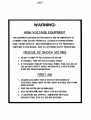
WARNING:
HIGH VOLTAGE EQUIPMENT
THIS EQUIPMENT CONTAINS CERTAIN CIRCUITS AND/OR COMPONENTS OF
EXTREMELY HIGH VOLTAGE POTENTIALS, CAPABLE OF CAUSING SERIOUS
BODILY INJURY OR DEATH. WHEN PERFORMING ANY OF THE PROCEDURES
CONTAINED IN THIS MANUAL. HEED ALL APPLICABLE SAFETY PRECAUTIONS.
RESCUE OF SHOCK VICTIMS
1. 00 NOT ATTEMPT TO PULL OR GRAB THE VICTIM
2. IF POSSIBLE, TURN OFF THE ELECTRICAL POWER.
3. IF YOU CANNOT TURN OFF ELECTRICAL POWER. PUSH. PULL OR LIFT
THE VICTIM TO SAFETY USING A WOODEN POLE. A ROPE OR SOME
OTHER DRY INSULATING MATERIAL.
FIRST AID
1. AS SOON AS VICTIM IS FREE OF CONTACT WITH SOURCE OF
ELECTRICAL SHOCK. MOVE VICTIM A SHORT DISTANCE AWAY FROM
SHOCK HAZARD.
2. SEND FOR DOCTOR AND/OR AMBULANCE.
3. KEEP VICTIM WARM. QUIET AND FLAT ON HIS/HER BACK.
4. IF BREATHING HAS STOPPED. ADMINISTER ARTIFICIAL
RESUSCITATION. STOP ALL SERIOUS BLEEDING.
TABLE OF CONTENTS
Para.
No.
Title
Page
FRONT MATTER
Title Page
Copyright Page
Warning Page
Table of Contents
i
Section l-INTRODUCTION
1-1
1-2
1-3
General
VIC-1541 vs. 1541
Warnings, Cautions and Notes
1-1
1-1
1-1
Section 2-CALIBRATION
2-1
2-2
2-3
2-4
2-5
2-5-1
2-5-2
2-5-3
2-5-4
2-6
2-6-1
2-6-2
2-6-3
General
Equipment Required
Preparation for Calibration
Calibration
Head Alignment
General
Equipment Required
Preparation for Mechanical Alignment
Head Alignment
Mechanical Alignment of Track #1 Stop
General
Preparation for Mechanical Alignment
Mechanical Alignment
2-1
2-1
2-1
2-2
2-4
2-4
2-5
2-5
2-5
2-8
2-8
2-8
2-8
Section 3-TROUBLESHOOTING
3-1
3-2
General
TROUBLESHOOTING-PART 1
3-1
3-2
Section 4-SCHEMATICS AND PARTS LAYOUT
4-1
General
4-1
APPENDICES
Appendix A
Appendix B
Video Detector Fabrication
Timing Strobe Fabrication
Page i
A-I
B-1
SECTION 1
INTRODUCTION
Section 1-INTRODUCTION
1-1.
General
The 1541 Maintenance Guide is produced to give a brief, concise
source of pertinent information necessary for maintenance of the
VIC-1541 and the 1541 disk drives. Most of the information in
this Guide has come from the 1541 Maintenance Manual, which is
also published by Peltier Industries. For those persons desiring
more thorough coverage of the 1541 series of disk drives, the 1541
Maintenance Manual is available through authorized dealers.
1-2.
VIC-1541 vs. 1541
The VIC-1541 (also known as the 1540) was the first generation of
the 1541 disk drive. Basically, COMMODORE selected certain
discrete components which were present on the VIC-1541 Disk
Controller PC Board and combined them in custom IC's. When they
did this, they renamed the disk drive the 1541 and changed the
reference designators (schematic identification of parts).
Functionally, there is very little difference between the two
versions. Text in this Guide refers to the VIC-1541. Section 4
contains the 1541 Disk Controller Schematic and Disk Controller PC
Board Parts Layout. For a complete discussion of the differences
between the two versions, the 1541 Maintenance Manual may be
consulted. For the purposes of this Guide, the following table
and close inspection of the 1541 Disk Controller Schematic will
enable 1541 owners to calibrate and troubleshoot their units.
1541 owners must cross-reference all test points before attempting
any of the procedures in this Guide.
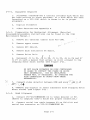
Jack/Plug Numbers
VIC-1541
1541
Jl/Pl
is
Jl/Pl
J2/P2---''_is
J8/P8
J3/P3 - _ is·--, J2/P2
J4/P4"
i-s -. ·---~J3/P3
J5/P5 '--'is
J5/P5
J6/P6{~
J6/P6
J7/P7 /
is
__ J7/P7
J8/Pg/
is'--J4/P4
J9
is
J9
1-3.
Warnings, Cautions and Notes
Throughout this Guide are a number of Warnings, Cautions and
Notes. A warning means that there is a possibility of serious
injury, or even death, to the technician if the Warning is not
heeded. A Caution means that there is a possibility of damage to
the VIC-1541 if the Caution is not heeded. A Note is intended to
serve as an aid to the technician in understanding text or in
following a procedure.
Page 1-1
SECTION 2
CALIBRA TION
Section 2-CALIBRATION
2-1.
General
T~tion
r 14q
I'l c
"contains step-by-step p:t;"ocedures for calibrating the
Only one calibration adjustment, to adjust the speed of
--iL-tl"'le"""""Clisk to 300 rpm, is provided in the VIC-1541.
Perform the
calibration procedure at the following intervals:
/"-\71(:-154)J
2-2.
1.
Every 6 months.
2.
During the process of troubleshooting.
3.
After a repair action.
Equipment Required
1.
Small slotted screwdriver
2.
Phillips screwdriver
3.
Timing light (Refer to Appendix B)
[Nont
•
4.
Any strobe light with an accurate
frequency of 50 Hz (+/- 1%) or 60 Hz (+/1%) may be used in place of the timing
light.
Blank floppy disk (5 1/4 inch, single sided)
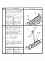
2-3. Preparation for calibration (Detailed disassembly/assembly
instructions can be found in the 1541 Maintenance Manual.)
1.
Remove top cover.
2.
Remove RFI shield.
3.
Disconnect
4.
Reinstall RFl shield.
5.
Remove bottom cover.
pi
from
J1.
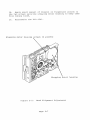
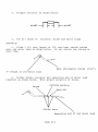
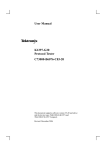
6. Place disk drive on left-hand side.
Use a thin book or
magazine to prop up drive.
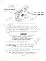
(Refer to Figure 2-1).
Page 2-1
ACCESS HOLE FOR VRl
TIMING DISK
Hz TIMING MARKS
Hz TIMING MARKS
Figure 2-1.
2-4.
VIC-1541 Prepared for Calibration
Calibration
1. Connect VIC-20/COMMODORE 64 to video monitor or TV.
(Refer to computer User's Guide for proper connection.)
1
2. Connect serial bus cable between P;yon VIC-1541 and serial
bus connector on VIC-20/COMMODORE 64.
3. Connect AC power cord between J9 on
outlet.
VIC-1541 and AC
IWARNINGI
•
USE EXTREME CARE TO AVOID CONTACT WITH
FRAME COMPONENTS. HIGH AC VOLTAGE
POTENTIALS ARE PRESENT DURING
CALIBRATION.
THESE VOLTAGE POTENTIALS
CAN CAUSE BODILY INJURY OR DEATH.
4.
Place VIC-1541 power switch to ON.
5.
Apply power to VIC-20/ COMMODORE 64.
6.
If a VIC-20 is the computer being used, enter the
following command:
OPEN 15,8,15,"UI-":CLOSE 15 <Return>
7.
Insert blank floppy disk into VIC-1541.
8. Plug timing strobe light into AC outlet.
near timing disk (Refer to Figure 2-1).
9.
position light
Enter following command into VIC-20/COMMODORE 64:
OPEN 15,8,15,"NO:CAL,OI":CLOSE 15 <Return>
Page 2-2
10. Adjust VR1 (Refer to Figure 2-1) until timing disk
appears to stop.
•
If 60 Hz AC is being used, calibrate with
the outer set of timing marks on the
timing disk.
•
If 50 Hz AC is being used, calibrate with
the inner set of timing marks on the
timing disk.
•
If further time is required to adjust
VR1, go back to Step 9 and re-enter
command given.
11. After drive motor has stopped, place VIC-1541 power
switch to OFF.
12.
Remove serial bus cable and AC power cord.
13.
Reassemble the VIC-1541.
Page 2-3
2-5.
Head Alignment
2-5-1.
General
This procedure aligns the read/write head to the physical tracks
on a floppy disk. A truly accurate alignment requires the use of
an alignment reference disk and a test program disk.
The
procedure which follows allows the user to "get by" without such
software. However, the degree of success achieved will depend on
the accuracy of the disk which is used. Consequently, the
alignment may cause compatibility problems when using software
recorded on other drives or when using other drives to read disks
recorded on a drive aligned with this procedure. This problem may
be reduced by selecting a pre-recorded disk which has not been
written to since it was recorded at the factory. Although this
procedure is not 100% accurate, it will usually suffice for the
home user.
For an accurate alignment of the drive unit, one of
the following alignment systems is recommended:
1.
COMMODORE System
This system is available from:
Commodore Business Machines,Inc.
Customer Service Dept.
1200 Wilson Dr.
Westchester, Pa. 19380
Alignment disk
Test program disk
Service manual
970160-01
970154-01
9900445
Total=
$130
$ 26
$ 25
$181
The above items, plus a dual trace oscilloscope, are
required to align a disk drive using the COMMODORE
system.
2.
Peltier Industries System
This system is available from:
Peltier Industries,Inc.
735 N. Doris
Wichita, Ks. 67212
Disk Alignment System (DAS-1541)
The system includes:
Alignment reference disk
Control disk
Instruction manual
Video detector
$39.95
The above items, plus a 3 1/2 digit, 100 Kohm digital
voltmeter, are required to accurately align a disk drive
using the Peltier Industries System.
Page 2-4
2-5-2.
Equipment Required
1. Alignment standard-use a factory recorded disk which has
not been written to since purchase, or a disk which has been
formatted on a VIC-1541 which is known to be in proper
alignment.
2.
Digital Voltmeter
3.
Video detector-see Appendix A
2-5-3. Preparation for Mechanical Alignment (Detailed
disassembly/assembly instructions can be found in the 1541
Maintenance Manual.)
1.
Remove all external cables from VIC-1541
2.
Remove upper cover.
'0-
~\
~ ~
\
3.
Remove RFI Shield.
4.
Remove Disk Controller PC Board.
5.
Remove Drive Unit.
(2
'.
"
!
"
!c
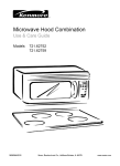
6. Reconnect J1 to PI, Ji to Pt, J5 to P5, J6 to P6 and J7
to P7 in such a manner that access is still allowed to the
stepping motor mount screws (See Figure 2-2).
DO NOT ALLOW PATHWORK ON DISK CONTROLLER
PC BOARD TO CONTACT THE FRAME OR DRIVE
UNIT ASSEMBLIES.
USE AN INSULATING
RUBBER MAT, IF NECESSARY, TO INSULATE THE
DISK CONTROLLER PC BOARD FROM THESE
ASSEMBLIES.
---'~~
7.
Connect, video detector between DVM and pins/7 arid 8 oj::
)JH'r:' . U
:-f
I
".
8 . '-Remove any Glyptol or other substance from stepping motor
mount screws (See Figure 2-2).
2-5-4.
Head Alignment
1. Connect VIC-20/COMMODORE 64 to video monitor or TV.
(Refer to computer User's Guide for proper connection.)
2. Connect serial bus cable between P3 on VIC-1541 and
serial bus connector on VIC-20/COMMODORE 64.
Page 2-5
3. Connect AC power cord between J9 on VIC-1541 and AC
outlet.
.I WARNING I
4t USE EXTREME CARE TO AVOID CONTACT WITH
FRAME COMPONENTS. HIGH AC VOLTAGE
POTENTIALS ARE PRESENT DURING
CALIBRATION. THESE VOLTAGE POTENTIALS
CAN CAUSE BODILY INJURY OR EVEN DEATH.
4.
Place VIC-1541 power switch to ON.
5.
Apply power to VIC-20/COMMODORE 64.
6.
If a VIC-20 is the computer being used, enter the
following command:
OPEN 15,B,15,"UI-":CLOSE 15<Return>
7.
Insert disk which will be used as the alignment standard
into the VIC-1541.
B. Enter the following program into the computer. This
program will place the head on track 16 and will leave the
drive motor running.
10
20
30
40
50
60
70
BO
9.
OPEN 15,8,15,"U+":OPEN 2,B,2,"#":OPEN B,B,B,"#"
PRINT #15,"B-P:";8;0:PRINT #15,"UA:";2;0;16;1
FOR X=l TO 9:READ Y
PRINT #8,Y;
NEXT X
PRINT #15,"M-E"+CHR$(0)+CHR$(5)
STOP
DATA 173,O,28,9,4,141,0,2B,96
Type RUN<Return>.
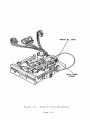
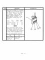
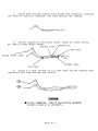
10. Loosen two screws (See Figure 5-2) securing stepping
motor housing to drive unit. Do not remove screws. Screws
should be just loose enough to permit rotation of the
stepping motor housing.
11. Rotate stepping motor housing while observing DVM
display. Voltage reading on DVM will increase or decrease
while rotating stepping motor housing. Correct position for
stepping motor housing is the position which produces the
largest voltage reading on DVM. Tighten the two screws when
this position is reached.
12.
Turn off DVM, disk drive and computer.
13. Disconnect all cables and test accessories from disk
drive.
Page 2-6
14. Apply small amount of Glyptol or fingernail polish to
the two screws securing stepping motor housing to keep them
from coming loose.
15.
Reassemble the VIC-1541.
Stepping motor housing ~W'
(2 places)
Stepping motor housing
Figure 2-2.
Head Alignment Adjustment
Page 2-7
2-6. Mechanical Alignment of Track
2-6-1.
'1
Stop
General
This procedure adjusts the Track #1 Stop. The Track #1 Stop is
used by the computer in the VIC-1541 for only two purposes:
1.
Formatting a blank floppy disk ("New" command).
2.
Soft error recovery.
The procedure that follows should only be used after carefully
verifying that the rest of the VIC-1541 is properly operating.
(Complete coverage of proper operation is given in
Troubleshooting-Part 2, in the 1541 Maintenance Manual.)
2-6-2. Preparation for Mechanical Alignment (Detailed
disassembly/assembly instructions can be found in the 1541
Maintenance Manual.)
1.
Remove all external cables from VIC-1541.
2.
Remove upper cover.
3.
Remove RFI Shield.
4.
Remove Disk Controller PC Board.
5.
Remove Drive Unit.
(I'
'6
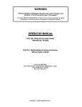
6. Reconnect J1 to P1, J~ to pi, J5 to P5, J6 to P6 and J7
to P7 in s'uch a manner that access is still allowed to the
(See Figure 2-3)
Track #1 Stop adjustment.
@AUTION!
•
2-6-3.
DO NOT ALLOW PATHWORK ON DISK CONTROLLER
PC BOARD TO CONTACT THE FRAI'IE OR DRIVE
UNIT ASSEMBLIES.
USE AN INSULATING
RUBBER MAT, IF NECESSARY, TO INSULATE THE
DISK CONTROLLER PC BOARD FROM THESE
ASSEMBLIES.
Mechanical Alignment
1. Connect serial bus cable between P3 and VIC-20/COMMODORE
64.
Page 2-8
Figure
2~3.
Track #1 Stop Adjustment.
Page 2-9
2.
Connect AC line cord between J9 and AC outlet.
I WARNING I
•
DO NOT CONTACT THE FRAME ASSEMBLY OR
WIRING. THE VOLTAGE POTENTIALS PRESENT
ON THESE PARTS COULD CAUSE SEVERE INJURY
OR DEATH.
3.
Place VIC-1S41 power switch to ON and place power switch
on computer being used to ON •
•
If the VIC-20 is the computer in use,
enter the following command:
OPEN lS, 8, lS, "U-": CLOSE lS <return>.
4.
Load the Display T&S program into the computer.
This
program may be loaded from the Test Demo disk or it may be
manually entered from the keyboard (The Display T&S program
is listed in Appendix C of the VIC-1S41 Single Drive Floppy
Disk User's Manual.).
S.
Place a factory recorded floppy disk into the VIC-1S41.
6.
Enter "RUN" <return> into the computer.
7. When the Display T&S program asks for a Track and Sector,
enter Track 1, Sector 1.
8. After the head settles and the Display T&S program begins
displaying Track information, adjust the Track #1 Stop
adjustment in the following manner (See Figure 2-3)~
a.
Loosen the adjustment lock-down screw.
b.
Place .006 inch feeler gauge between Stop and
potrusion on the stepping motor hub. Carefully adjust
the Stop until feeler gauge just touches the potrusion
on the stepping motor hub and the Stop .
•
00 not disturb position of the stepping
motor shaft.
c.
Tighten the adjustment lock-down screw.
9.
Place VIC-1S41 and VIC-20/COMMODORE 64 power switches to
OFF.
10.
Reassemble the VIC-1S41.
Page 2-10
SECTION 3
TROUBLESHOOTING
Section 3-TROUBLESHOOTING
3-1.
General
This
section requires
only a
Mul timeter
(digital
type
is
recommended) and will isolate a problem down to the sub-assembly
level.
It is set up so that even an electronics novice can
perform the procedures.
Troubleshooting consists of step~by-step
procedures with accompanying illustrations. Each step either asks
a question or refers to the following step.
When a question is
asked, answer the question with a "Yes" or "No".
Below each
question are two blocks labeled "Yes" and "No".
Follow the
instructions in the appropriate block.
The instructions will
either lead to another step or will isolate the problem to a
particular sub-assembly.
At this point, the faulty sub-assembly
may be replaced or the sub-assembly may be repaired down to the
component level using the procedures in Troubleshooting-Part 2 in
the 1541 Maintenance Manual.
Page 3-1
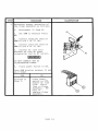
8-2.
TROUBLESHOOTING-PART 1
STEP
PROCEDURE
1
ILLUSTRATION
Remove AC line cord and serial
bus cables.
Remove top cover.
Remove fuse from fuseholder.
Measure resistance of the fuse
as follows:
1.
Set DMM (Digital
Multimeter) to Ohms x 10 or
Ohms x 100.
2.
Connect common lead of DMM
to one end of fuse (A).
3. Connect positive lead of
DMM to other end of fuse (B).
Does DMM display less than 10
ohms?
YES
Install fuse
and proceed
with Step 2.
NO
Replace fuse
with a new fuse
of proper rating & size.
Then proceed
with Step 2.
Page 3-2
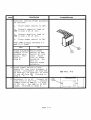
STEP
2
ILLUSTRATION
PROCEDURE
Determine proper operation of
the frame assembly as follows:
1.
Disconnect J1 from Pl.
2.
Set DMM to measure Volts
AC.
3. Connect negative lead of
DMM to pin 1 of J1 (A).
4. Connect positive lead of
DMM to pin 4 of J1 (B).
5.
Connect AC line cord
'between J9 (the AC power
receptacle) and an AC outlet.
Pi
IWARNINGI
DO NOT CONTACT ANY AC
DISTRIBUTION LINES.
6.
Place power switch to ON.
Does DMM display between 15 and
21.5 Vrms?
YES
'Proceed to
Step 3.
NO
Place power
switch to OFF.
Remove AC line
cord.
Fault
lies in Frame
Assembly.
Repair or
replace Frame
Assembly.
Page 3-3
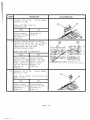
B
PROCEDURE
STEP
3
ILLU~T~TION
(Continue testing Frame Assembly
,as follows:
1.
Place power switch to OFF.
2. Connect negative lead of
iDMM to pin 2 of J1 (A) •
3. Connect positive lead of
.DMM to pin 3 of J1 (B) •
4.
Place power sw;itch to ON.
Does DMM display between 9.5
and 13.5 Vrms?
YES
Frame Assembly
appears to be
·working properly.
Proceed to
Step 4.
4
NO
Place power
switch to OFF.
Remove AC line
,cord.
Fault
lies in Frame
Assembly.
Repair or
replace Frame
Assembly.
Place power switch to OFF.
Remove AC line cord. q.j.Remove 'b
shield.
Disconnect Jf from
,J5 from P5, J6 frpm P6, J7 from
P7 and Jj{ from P~..1
Proceed to
$tep 5. '1
V\
pi,
5
Reconnect J1 to Pl.
Connect AC
line cord to VIC-1541.
Connect
common lead of DMM to (-) side
of C52 (A).
Set DMM to 20 VDC
range.
Proceed to Step 6.
Page 3-4
SEE FIG. 9-2
PROCEDURE
STEP
6
ILLUSTRATION
Place power switch to ON.
Measure tests points in table
below. Touch positive lead of
DMM to indicated test point.
Verify that each measurement is
within the minimum and maximum
limits given.
Test Point
Min.
Max.
PS,pin1(A)
P7,pin1(B)
P7,pin2(C)
P5,pin2(D)
P6,pinS(E)
P6,pin2(F)
+4.6V
+11.4V
+11.4V
+11. 4V
+4.75V
+4.6V
+5.25V
+12.6V
+12.6V
+12.6V
+5.25V
+5.25V
Are all measurements above
within limits specified?
YES
Place power
switch to OFF.
Proceed to
Step 7.
7
NO
Place power
switch to OFF.
Remove AC line
cord. Fault
lies in Disk
Controller PC
Board. Repair
or replace.
Connect J~ to Pj.
swi tch tofON.
'1
Place power
Is green LED illuminated?
YES
Place power
switch to OFF.
Proceed to
Step S.
NO
Place power
switch to OFF.
Remove AC line
cord. Fault
lies in Case
Assembly.
Repair or
replace.
Page 3-5
STEP
8
PROCEDURE
Connect J6 to P6.
switch to ON.
ILLUSTRATION
Place power
Does red LED come on
momentarily?
YES
NO
Place power
Proceed to
switch to OFF. Step 9.
Proceed to
Step 10.
9
Using a short piece of wire,
carefully short pin 10 of UF2E
(A) to pin 1 of P6 (B) while
observing the red LED
(Error/Access LED).
Does red LED illuminate?
YES
Place power
switch to OFF.
Fault lies in
Disk Controller PC Board.
Repair or
replace.
10
NO
Place power
switch to OFF.
Fault lies in
Drive Unit.
Repair or
replace.
Connect JS to PS.
switch to ON.
Place power
Does drive motor turn while red
LED is on?
YES
Place power
switch to OFF.
Proceed to
Step 12.
NO
Place power
switch to OFF.
Proceed to
,Step 11.
Page 3-6
STEP
11
PROCEDURE
ILLUSTRATION
Connect positive lead of DMM to
pin 3 of J5 (A). Observe DMM
while placing power switch to
ON.
Does DMM indicate 0.0 to +0.8 V
when the red LED is
illuminated?
NO
YES
Place power
switch to OFF.
Fault lies in
Drive Unit PC
Board.
Repair
or replace.
12
Place power
switch to OFF.
Fault lies in
Disk Controller PC Board
Repair or
replace.
Using two short lengths of
wire, carefully connect pins 1
and 2 of J7 to pin 1 of P7.
Place power switch to ON.
Using a third piece of wire,
short sequentially between pin
1 of P6 and each of the test
points indicated below.
Observe read/write head while
shorting each test point.
1.
2.
3.
4.
J7,
J7,
J7,
J7,
pin
pin
pin
pin
4 (A)
5 (B)
3 (C)
6 (D)
Verify that the read/write head
moves toward the front of the
VIC-1541. Repeat the procedure
in reverse order and verify
that the read/write head moves
toward the rear.
Does the read/write head move
in the proper direction?
YES
Place power
switch to OFF.
Proceed to
Step 13.
NO
Place power
switch to OFF.
Fault lies in
Drive Unit.
Page 3-7
J5
STEP
13
PROCEDURE
ILLUSTRATION
Remove wires from J7. Connect
J7 to P7. Remove negative lead
of DMM from (-) side of C52.
Set DMM to Ohms x 10 or Ohms x
100 range. Connect negative
and positive leads of DMM to
pins of J,~as indicated in
table below. Verify
resistances indicated on DMM
are within limits given in
table.
(-)
lead
(+)
lead
Ohms
Min.
pin1(A) pin5(D)
pin1
pin4(C)
pin1
pin3 (B)
Ohms
Max.
29
12
23
39
22
33
[... 9n!
This resistance check of the
read/write head does not check
its dynamic characteristics.
If in doubt about the condition
of the read/write head, refer
to Part 2 of Troubleshooting.
Are all resistances correct?
YES
NO
Place power
Fault lies in
switch to OFF. Drive Unit.
Proceed to
Replace.
Step 14.
Page 3-8
J2
STEP
14
PROCEDURE
,
ILLUSTRATION
Connect J~ to vi. Perform
Calibration pro~edure in
Section 2.
Is drive motor rotating at
,correct speed?
YES
J2
NO
At this point Fault lies in
the problem
Drive Unit.
lies in the
Dis k Con tro 1- a...R.e.p.l.a_c.e••_"",!"_ _ _, ,
ler PC Board or in the Drive
Unit.
To determine which of
the two sub-assemblies is
bad, refer to Part 2 of
Troubleshooting in the 1541
Maintenance Manual.
Part 2
requires an oscilloscope
and some technical experience.
If you do not wish to
attempt Part 2, try swapping
the Disk Controller PC Board
or the Drive Unit with a
known good assembly and see
if the problem is solved.
Also, check assemblies for
obvious signs of wear or
damage.
Page 3-9
SECTION 4
SCHEMATICS
AND
PARTS LAYOUT
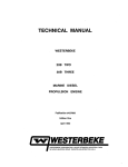
Section 4-SCHEMATICS AND PARTS LAYOUTS
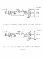
4-1.
General
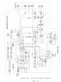
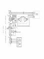
This section contains Schematics, Parts Layout Drawings, a
Functional Block Diagram and an Interconnect Diagram.
These
figures are provided for reference purposes. The following index
is provided for user convenience:
Figure
Title
Page
4-1
Interconnect Diagram
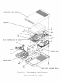
4-2
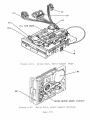
4-2
Sub-Assembly Identification
4-3
4-3
Functional Block Diagram
4-5
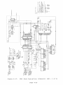
4-4
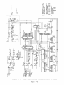
Disk Controller, Schematic (Sht. 1 of 2 )
4-6
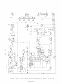
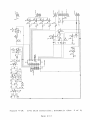
4-5
Disk Controller, Schematic (Sht. 2 of 2 )
4-7
4-6
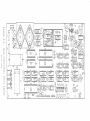
Disk Controller, Parts Layout
4-8
4-7
Case Assy, Schematic
4-9
4-8
Case Assy, Parts Layout
4-9
4-9
Drive Unit, Schematic
4-10
4-10
Drive Unit, Parts Layout (Top)
4-11
4-11
Drive Unit, Parts Layout (Bottom)
4-11
4-12
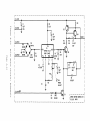
Drive Servo Circuit, Schematic
4-12
4-13
Drive Servo Circuit, Parts Layout
4-13
4-14
Frame Assy, Schematic (115 VAC)
4-14
4-15
Frame Assy, Schematic (230 VAC)
4-14
4-16
Frame Assy, Parts Layout
4-15
4-17
1541 Disk Controller, Schematic (1 of 2)
4-16
4-18
1541 Disk Controller, Schematic (2 of 2)
4-17
4-19
1541 Disk Controller, Parts Layout
4-18
Page 4-1
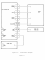
TRACK
SELECT
DISK CONTROLLER
~~
0E]
0
J7
---------1/
I
G8,..-------,....---1/
DRIVE
UNIT
I
~~ ~~~--------I/
I
R~t!J 0f-------~/
I
Ip~~~
r:
BUS
~--------~
eJI~r-------f/
CASE ASSY
(PWR LED)
~--------~
I
IJ)SER~
BUS
INPUT
POWER
I
0LJ
JI
I
I
EJ
9
FRAME ASSY
AC
LINE
I
Figure 4-1.
Interconnect Diagram
Page 4-2
CASE ASSY (TOP HALF)
SHIELD
P7
DISK CONTROLLER PC
Jl
J5
FRAME ASSY
J~
~
Figure 4-2.
CASE ASSY (BOTTOM HALF)
Sub-Assembly Identification
Page 4-3/(Page 4-4 Blank)
~
-
~
)0,
I/)
~
---------------------------------------1
- - - - - - --1
f: . f"· ~ ".
I
I
~
~;
:I
«
o_ _ _ _ _ _ _ _ II
~~~~
~! ~ ~ ~
I
I
I
I
I
I
I
1_ _ _ _ _ _ _ _ _
____ _
---------- - - - - - - - - - - - - - - - -----
g
~
iIi....
....
oII:
I-
Z
o
o
I
l.:
I
I
(/)
i3
I
"---------------"1
I
I
I
I
I
)0,
'"'"«
I-
Z
:::I
W
>
a:
o
I
1_ _ _ _ _ _ - - - - - -
Figure 4-3.
Functional Block Diagram
Paqe 4-5
I
5 ~=0
~
""'C.
==
=i
~.
;! ~i
~S
~i !~
tJUUU
~=
~~~
~="~
.~U
(5+:;
~~a
=E~
~.~
§o
~=
.
~
~
0
tio~~
Q
"'lOla ....
:; ;II!I
a"'<I\~:::
~
~~III
~
55~B ~~
~~
~tH:n:l .~
"'",,00.-1
....
"'
... ..,
UUUU
2~i
~~ ~~ ~U
~
uuuu
UUuu
~5
uuuu
:+-1
tl..
'~I
i I
II.
~
~
~
I
''4 ;;."I ,
~:r
..~
iiiii
H
llniiiillm~ I
r
r
I
I
r
............. v=!!'!:I:'II.!::
I
I
I
I,
I.
IL _
~ ______________
..
_
..
i
;: A;.;:
llli
<
Figure 4-4.
Disk Controller, Schematic (Sht. 1 of 2)
Page 4-6
!:::>;l~
t-'Q"""~::~
~2
I_
~...
I
..
t
'u,
Figure 4-5.
Disk Controller, Schematic (Sht. 2 of 2)
Page 4-7
0
-'E3
m.O £~~ ~;ij=~
"':I
C
1-1
CD
I
~ if ~ ~
0"',
I
I
us£>
U
un;
100° 0 0 00
0000000
I
0
UCD5
"'en.....
()
0
,.
:J
rT
1-1
I
0
0
I-'
I-'
D
ill
1-1
'1j
OJ
1-1
rT
u' ._.
••
Os ~8"
..
nn 0'
lO
UUHY.
~l
rn
I I
L;::J
325302-01
22XE
"",'0
UA84
r - ,
t'"
OJ
I
'<
0
C
'0
i~O
'88' 0
LIS
P5
"o~o~o-u-o-o-o-'I
~R31
!~
q~
<I
1;1
0
<I
~O
<I
a
UO
C2:3
010
lU
~QO~OP~OP~
~ ~"7
PC
U
8150
E:::::I'O
UH4
uO
",p",
lM
:311N
~OD
....
~
O~O
11(;">;
Q
I
~Io';'Cu~-o~o~o-o-o
0
<I
01
%o~~;?M0
,~
P7
I)
() ()
'6
:>0<
P6
<I 1;1 1;1 <I
(jI
Uo,
~::::::::: I~O :::::::::
I C52
09
(jI
010 ,;,
[~::::~~~:=:~:]c
Vl'-"-"--
I
CSCS·
lffi)c
,,-:i
'" 0
V
ou.QO
.~ 1
~
.a 0
nnn
~ "Uy~~y .'0 o:O~"
08
N
N~:::.l
"".
tUDD
en
rT
. _]
U-~i{~-
~
~
0
~oOO ·0~~O~O~O"o~ ~;"7 0
"'"
~
'.
°00, uYr5~~~y ~~ .yy'
"'.
<.0
0
0
"
rtZ
000'0
d
(J
04
@
Q5
C62
@
Q6
07
""
C~
+
o
~
~,
,~
"\,
r-JJi.
PWR LED I
- - - - - - PWRLEO
N/C
~ -b
I
3
I
L
____
Figure 4-7 .
I
I
r--~I
I CASE ASSY- -,I
2
GNO
POWER
OSI
(GN)
-,
-.J ____ J
Case Assy , Schematic
DSl
Figure 4-8 .
Case Ass y, Parts L ayout
Page 4-9
J5, DRIVE MOTOR
OR
OFFION
h:j
f-'.
LQ
C
i"i
CD
g-
+t2V
GND
1111
:
r - - - - -
N/C
HEAD A
I
\0
to
Pl
LQ
CD
.I:>
I
t-'
0
t::1
i"i
<:
CD
c::
:::l
f-'.
rt
BiAS
I
1,'I
I
J6. OPTICS
RD
+5V
:
I
DSI
ACCESSI
3
4
WRITE PROTECT LED 2
WRITE PROTECT
12
NIC
CD
3
III
ERROR LED
J.;"9K"-_ _ _ _ _ _....
~L¥:B~~RD::-------,
1-"''-''''---...,
7
QI
Nle
6
NIC
10
CRI
Nle
Nle
Nle
II
14
"
WRITE PROTECT EMITTER
WRITE
J7; TRACK SELECT
+12V
+12V
rt
e3
el
0
02
04
f-'.
:
RO
!b.
JlR
.!!!!.
9R
I
/
I
L _________ J
I
L __________________
J
GND
GND
0
~
- ..,
I
HEADB
ERRO~/~ED
- - -
19K
(/)
::r
BI
BIAS
N/C
N/C
f-'.
itcfTORITACHOMETEft -
-
B2
STEPPING
MOTOR
OFFION
+12V
E3 GND
ac'lI.n/WI:NTe UI:'Aft
.I:>
I
;--------------,
~ EI
E2
9R
BK
,-------00o E5,
E6.M+
I
I
DRIVE MOTOR
SERVO CIRCUIT
TACH
, - - - - - _ , E4.TACH
L_' ____________
I
J
J5
J7
~~~~----------J6
Q1
CR1
Figure 4-10.
Drive unit, Parts Layout (Top)
B2
DS1
DRIVE MOTOR SERVO CIRCUIT
Figure 4-11.
Drive Unit, Parts Layout (Bottom)
Page 4-11
--------l
I EI. +OV
"'l
f-'.
LQ
C
+
'
I
0E3,GND
-I
I
I
Q'
CI
II
IO~F
35V
I
....
11
(I)
E6.M+ I
0I>-
I
I-'
tv
I E4,TACH
7
I
CR3
Vee
ICI
FB SPEED CTLR OUTI-5~
SONY 2463
FIL RI
GND
R2
I
I
3
4
8
tJ
11
f-'.
'U
OJ
LQ
(I)
<:
(I)
en
(I)
11
01>-
I
<:
0
I-'
IV
\.)
f-'.
11
0
C
f-'.
rT
~
en
0
::r
(I)
:3
I E5,TACH
I
I
I
I
I
I
I
I
I
I E2,ON/OFF
f-'.
I
0
....
.,.
J-
~
1 I l
-
4~~1
L _ _ _ _ _
....
+
R5
2.7K
\
\
C7
O.47pF
35V
\
RIO
\
\
\
J
R7
10K
_
_
_
_
_
_
_
_
_
_
_
_
C8
O.063pF
0VRI
SPEED
ADJUST
R2
C3
_
OJ
rT
RI
10K
CR2
IN4148
_
_
CR5
IN4148
_
_
*
' 0 ( QI
_
_____
r -
-
-
-
-
-
J
J
I DRIVE MOTOR SERVO CKT·I
BD._ASSY
L P.C._
___ _
>
~
+W
0Z
I~.....
z
0
N
I1J
0
::r:
::r:
~
q-
~
ui
0
z
(!)
~
I1J
I1J
O~O
o
IIlIll
(!)
0
I1J
+
::E
..;
I1J
0 0
>-
a:
~
~@[ w.i)
000
I~
CO
....
O~m ~1~trJ~
o~
Figure 4-13.
Drive Servo Circuit,
Page 4-13
Parts Layout
JI,AC INPUT
J9,AC LINE
SI,POWER
16V 1211
OFF
AC HI
GND
ON
16V 02
AC LO
9V 01
9V 02
Figure 4-14.
Frame Assy, Schematic (For use with P.C.Bd. 1540048-xx)
TI
J9,AC LINE
JI,AC INPUT
SI,POWER
16V
01
OFF
AC HI
GND
ON
AC LO
Figure 4-15.
16V
02
9V
01
9V
02
Frame Assy, Schematic (For use with P.C.Bd. 1540001-xx)
Page 4-14
Jl
Figure 4-16.
Frame ASsy, Parts Layout
Page 4-15
"'~t.lZZ
~§ij~
0"-0"....l0..10
U
U
-- -
-,
I
-----~------~ r-- --- --------------,
r>
I
I
: :~l"':
~
I
i
.~ ffi~·
Q:l;
~'
!:
~ _ ~,E
I
:
"'-41'
~~
Hg
H
:
~
!
I
I
I
I
I
I
I
I
I
I
I";
L _________________
Figure 4-17.
I
~
1541 Disk Controller, Schematic (Sht. 1 of 2)
Page 4-16
·1,
,
.,
I"· ,
~.;
4';
Figure 4-18.
1541 Disk Controller, Schematic (Sht. 2 of 2)
Page 4-17
.,
10 0~O-I
"J
f-'.
1..j:C
,:
r:
(I)
~
I
f-'
,~'
0'8
pG
0.0.
D
~
'-!.)
O~
r-'
O~15
~n
u~
Yd
~
1'------ ..
I
ouooooo
I.J1
.'4
U8.
t:'
f-'.
901229- 03
Ul
'tJ
A
OJ
n
'.:j
(l)
,':.
I
f~
365AA6 - 3<:1
luuuuuuuuuuuul
us,
0
O[==t=I~'M~OOO'
_
C~~
~OOdQt\-~-J--?~
~
0
-L;,?,.~
~_~
B~P9
325302-01
0
'2
o
~
(1)
r:
'tJ
UB2
H.:~:P"
~
UJ
r:
~
UC2cn
OfOOOOOOOO~~fOOOOOOOOOI 0,0000000'
LU~UUUUI.Jl.J1,.;7~~
G=
(T
Ul
325572- 01
UAI
64ftI05U
t"
8:508 COO
CJ
'<
0
c:
rt
_.,
W
........0.
'
?
Bk
"'~Y~
,t-
r:
I--'
_
m
:J
0)
2
g~QO
~<p
~
......
OQ'
P3
l14GL13G-
~
~
~
.,
E!3
uc'
--c5~
E::!::!]
I
a a a
~
0
a a ., a a a a a a a a
I
10
a
"a a 01
0.
cS'
+
PO
~
~
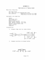
APPENDIX A
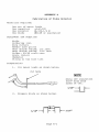
APPENDIX A
Fabrication of Video Detector
Materials Required:
One
One
One
One
set of meter leads
capacitor
.oluF,50V
resistor
lK,10%,1/4 W
diode
IN4148 or equivalent
Equipment and Supplies:
Knife
Soldering iron
Wire cutters
Needle nose pliers
Heat shrink tubing, 1/2 inch
Heat shrink tubing, 3/16 inch
Solder, 60/40 resin core
Scale (ruler)
Ohmmeter
String or two wire ties
Preparation:
1.
Cut meter leads as shown below:
cut here
Strip off insulation
3/16" from both
sides of cut.
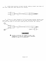
2.
Prepare diode as shown below:
3/16"
--.r=~::rlPage A-I
3/16"
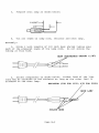
3.
Prepare resistor as shown below:
4.
Tin all leads on
resistor, diode and meter leads
Assembly:
1.
Slide 1 1/2 inch length of 1/8 inch heat shrink tubing
onto red meter lead as shown below. Do not shrink the tubing at
this time.
Heat shrinkable tubing (3/16")
3" length of red meter lead
2. Solder diode, resistor and remaining end of meter lead
together as shown below. Note proper polarity of diode.
Cathode marking
Remaining end of red meter lead
Page A-2
3. Slide heat shrink tubing over diode and resistor, leaving
one lead of resistor exposed, and then shrink the tubing.
4.
Solder capacitor and black meter leads as shown below.
Tie meter leads where shown.
Solder here
Tie here
Tie here
5. Slide a 2 inch length of 1/2 inch heat shrink tubing over
capacitor and then shrink the tubing .
•
USING OHMMETER, VERIFY RESISTANCE BETWEEN
POINTS A AND B IS INFINITY.
Page A-3
APPENDIX B
APPENDIX B
Fabrication of Timing Light
Materials Required:
One neon bulb
One lamp cord with appropriate plug
One resistor
22K,10%,1/4 W (for 115 VAC)
47K,10%,1/4 W (for 220 VAC)
Equipment and Supplies:
Knife
Soldering iron
Wire cutters
Needle nose pliers
Heat shrink tubing, 1/8 inch
Heat 9hrink tubing, 3/16 inch
Solder, 60/40 resin core
Scale (ruler)
Ohmmeter
Preparation:
1.
Prepare lamp cord as shown below:
2.
Prepare resistor as shown below:
3/16" - r f t = f . - - 3 / 16"
Page B-1
3.
Prepare neon lamp as shown below:
11/16n~
1/4"
.:::-1
~
I
c(~!It.f====t
4.
Tin all leads on lamp cord, resistor and neon lamp.
Assembly:
1. Slide 1 inch lengths of 1/8 inch heat shrink tubing onto
each of the prepared leads of the lamp cord. Do not shrink the
tUbing at this time.
HEAT SHRINKABLE TUBING (1/8 R
)
4DTIt===lll=/f~~
2. Solder components as shown below. Either lead of the line
cord may be soldered to the resistor as long as the other lead is
soldered to the neon lamp.
RESISTOR (22K FOR 11SV, 47K FOR 220V)
SOLDER HERE
Page B-2
3.
Slide both pieces of heat shrink tubing toward the base of
the neon lamp and then shrink the tubing.
4.
Slide a 2 inch length of 3/16 inch heat shrink tubing over
neon lamp.
Position the end of the heat shrink tubing 3/16 inch
up from the base of the neon lamp and then shrink the tubing.
IWARNING'
•
BEFORE PLUGGING IN TIMING LIGHT, USE
OHMMETER TO VERIFY RESISTANCE BETWEEN
POINTS A AND B IS INFINITY.
Page B-3
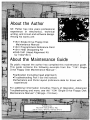
About the Author
Mr. Peltier has nine years professional
experience in electronics, technical
writing, and circuit and software design.
Among his works are:
-1541 Single Drive Floppy Disk
Maintenance Manual
-1541 Programmers Reference Card
-1541 Heat Dissipating Kit
- DAS-1541 (Head Alignment Kit
for 1540/1 541 )
About the Maintenance Guide
By public request the author has compiled this maintenance guide.
This guide contains the following excerpts from the "1541 Single
Drive Floppy Disk Maintenance Manual":
-Calibration (including head alignment)
-Troubleshooting Part I (for the novice)
-Schematics and Parts Layout (reference data for those with
experience)
For additional information including; Theory of Operation, Advanced
Troubleshooting and more, see the "1541 Single Drive Floppy Disk
Maintenance Manual" (198 pgs.-118 illus.)