1
OPERATOR'S MANUAL
WESTERBEKE
4.5 KW BeG
MARINE GASOLINE
GENERATOR SET
Publication #037491
Edition 1
November 1988
/-vtT' WESTERBEKE
"
WESTERBEKE CORPORA TlON
•
A VON INDUSTRIAL PARK, A VON, MA 02322. TEL: (508) 588-7700
Gasoline with an ETHANOL content
higher than 10% (E10) is not allowed
and may void warranty.
Engines & Generators
SAFETY PRECAUTIONS
The following symbols appear in this manual to call attention
to and emphasize conditions potentially dangerous to the
•
operator.
Use Extreme Care When Handling Engine Euel
(A constant danger of explosion or fire exists)
Do not fill fuel tank(s) while the engine is running.
Do not smoke or use an open flame near the engine orthe
fuel tank.
iWARNINGJ
The above symbol is used in the manual to warn of possible
serious personal injury or loss of life.
•
Be sure all fuel supplies have a positive
CAUTION
of possible damage to equipment.
•
Use insulated mats whenever working on electrical
ment.
equip~
Make sure your clothing is dry, not damp (particularly
shoes), and keep your skin surfaces dry when handling
electrical equipment.
Remove wristwatch and jewelry when working on electri~
cal equipment.
Do not connect utility shore power to vessel's AC circuits,
except through a ship~to~shore double~throw transfer
switch. Damage to vessel's AC generator may result if this
is not done.
Be extremely careful when working on electrical
ponents. High voltage can cause injury or death.
~
Lead acid batteries emit hydrogen, a highly~explosive gas,
which can be ignited by electrical arcing or by a lighted
Cigarette, cigar, or pipe. Do not smoke or allow an open
flame near the battery being serviced. Shut off all electri~
cal equipment in the vicinity to prevent electrical arcing
during servicing.
Prevent Electric Shock
equip~
com~
Exhaust Gases Are Toxic
Ensure that the exhaust system is adequate to expel gases
discharged from the engine. Check exhaust system
regularly for leaks and make sure the exhaust manifolds
are securely attached and no warping exists.
Be sure the unit and its surroundings are well~ventilated.
Use Extreme Care When Servicing Batteries
Wear rubber gloves, a rubber apron, and eye protection
when servicing batteries.
Always operate bilge blowers for at least five minutes before
starting a gascline~fueled engine; ensure no gasoline fumes are
present before starting.
Shut off electric power before accessing electrical
ment.
valve.
Make sure a fire extinguisher is installed nearby and is
properly maintained. Be familiar with its proper use. Ex~
tinguishers rated ABC by the NFPA are appropriate for all
applications encountered in this environment.
Read the manual carefully and thoroughly before attempting
to operate the equipment. Know when dangerous conditions
can exist and take necessary precautions to protect personnel
and equipment.
Fuels, exhaust gases, batteries, electrical equipment, and
moving and hot parts are potential hazards that could result in
serious personal injury or death. Follow recommended proce~
dures carefully.
shut~off
Be certain fuel line fittings are adequately tightened and
free of leaks.
The above symbol is used in the manual to caution personnel
4&
Do Not Alter or Modify the Ellel System
4»
Ayoid Moving Parts
Do not service the unit while the unit is running; if a situa~
tion arises in which it is absolutely necessary to make
operating adjustments, use extreme care to avoid moving
parts and hot exhaust system compooents.
Do not wear loose clothing or jewelry when servicing
equipment; avoid wearing loose jackets, shirts or sleeves,
rings, necklaces, or bracelets that might be caught in
moving parts.
Make sure all attaching hardware is properly tightened.
Keep protective shields and guards in their respective
place at all times.
Do not check fluid levels or the drive-belt's tension while
the unit is operating.
Do not work on the equipment when mentally or physical~
Iy incapaCitated by fatigue.
IMPORTANT
PRODUCT SOFTWARE DISCLAIMER
Product software of all kinds, such as brochures, drawings, technical data, operator's and workshop manuals,
parts lists and parts price lists, and other information, instructions and specifications provided from sources
other than Westerbeke, is not within Westerbeke's control and, accordingly, is provided to Westerbeke customers only as a courtesy and service. Westerbeke cannot be responsible for the content of such
software, makes no warranties or representations with respect thereto, including the accuracy, timeliness or completeness thereof, and will in no event be liable for any type of damages or injury incurred
in connection with, or arising out of, the furnishing or use of such software,
For example, components and subassemblies incorporated in Westerbeke's products and supplied by others
(such as engine blocks, fuel systems and components, transmissions, electrical components, pumps and
other products) are generally supported by their manufacturers with their own software, and Westerbeke
must depend on such software for the design of Westerbeke's own product software. Such software may
be outdated and no longer accurate. Routine changes made by Westerbeke's suppliers, of which Westerbeke rarely has notice in advance, are frequently not reflected in the supplier's software until after such changes take place.
Westerbeke customers should also keep in mind the time span between printings of Westerbeke product
software, and the unavoidable existence of earlier, non-current Westerbeke software editions in the field. Additionally, most Westerbeke products include customer-requested special features that frequently do not include complete documentation.
In summation, product software provided with Westerbeke products, whether from Westerbeke or other suppliers, must not and cannot be relied upon exclusively as the definitive authority on the respective product.
It not only makes good sense but is imperative that appropriate representatives of Westerbeke or the supplier in question be consulted to determine the accuracy and currency of the product software being consulted by the customer.
1
Westerbeke Generators
FOREWORD
Thank you for selecting a Westerbeke marine product for your use. We at Westerbeke are pleased to have
you as a customer.
Read this manual carefully and observe all safety precautions included throughout. Operating procedures,
periodic preventive maintenance procedures, installation checks, system descriptions and minor adjustment procedures are included herein so you can operate your equipment safely and properly, maintain the
equipment at a high level of efficiency, and expect dependable periormance and long service life in return.
Should your unit require special attention, contact your Westerbeke dealer for assistance. The Westerbeke
Service Organization is trained to provide the support necessary to ensure long-term dependable periormance.
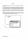
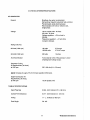
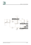
If, within 60 days of submitting the Warranty Registration Form for your un~, you have not received a Customer Identification Card (see below) registering your warranty, please contact the factory in writing with
Model information, including the unit's serial number and commission date.
from:
WESTERBEKE CORPORA liON
AVON INDUSTRIAL PARK
AVON, NA 02322
I~I
WESTERBEKE
......
... - .........
,-......
...,,, .-, .......... -...--
_
,-"
'
_._,
"""'I
CUSTOMER IDENTIFICATION
Adam Silith
as
Mail To:
Maple Street
Alden. IN 12234
Model
8CG4.SKW
Sa r.
I 1234C896
Expiree 11/15/89
~
Westerbeke Generators
~
2
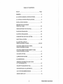
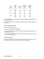
TABLE OF CONTENTS
Section ......................................................................... Page
GENERAL ........................................................................... 5
4.5 K:N BCG GENERAL SPECiFiCATIONS ....................... 8
4.5 K:N BCG SYSTEM SPECiFiCATIONS ......................... 9
INSTALLATION CHECKS ................................................. 12
DESCRIPTION OF ENGINE
CONTROL PANEL. ........................................................... 25
PREPARATIONS FOR STARTING ................................... 27
STARTING PROCEDURE ................................................. 28
STOPPING PROCEDURE ................................................ 30
CARBURETOR AND FUEL SYSTEM ............................... 32
ELECTRICAL SYSTEM ..................................................... 35
DC CONTROL CIRCUIT
WIRING DIAGRAM # 38028 .................................... 38 & 39
OPTIONAL REMOTE START PANEL
WIRING DIAGRAM # 38024 ............................................ 40
OPTIONAL REMOTE INSTRUMENT PANEL
WIRING DIAGRAM # 38025 ............................................ 41
COOLING SySTEM .......................................................... 42
LUBRICATION SYSTEM .................................................. 48
BC GENERATOR .............................................................. 51
GENERAL INFORMATION AND CARE
OF THE GENERATOR ..................................................... 57
ENGINE TROUBLESHOOTING ....................................... 59
MAINTENANCE & ADJUSTMENTS ................................. 63
LAY-UP & RECOMMISSIONING ..................................... 71
SPARE PARTS LIST ......................................................... 74
3
Westerbeke Generators
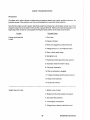
TABLE OF CONTENTS
(CONTINUED)
TABLE OF STANDARD HARDWARE
TIGHTENING TORQUES ..................................................75
TABLE OF TIGHTENING TORQUES ............................... 76
INDEX ................................................................................77
Westerbeke Generators
4
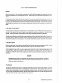
GENERAL
Introduction
This manual contains the equipment operating procedures as well as additional information needed to help
the operator keep the marine equipment in proper working order. Study and follow the instructions carefully. A planned maintenance program is included in this manual; adhering to the program will result in better
equipment performance and longer equipment life. Proper diagnosis of a problem is the most important step
to satisfactory repair; therefore, a troubleshooting table is included.
Understanding the Gasoline Engine-Driven Generator
The gasoline engine driving an AC generator is in many ways similar to a gasoline automobile engine. The
cylinders are vertical in-line, and the engine's cylinder head has an overhead camshaft which is belt-driven.
The engine utilizes conventional points and a condenser-type distributor which is horizontally mounted and
camshaft-driven. The engine incorporates a pressure-type lubrication system, and a fresh water-cooled engine block which is thermostatically-controlled. To a large degree, the generator's engine requires the same
preventive maintenance that is required of a gasoline automobile engine. The most important factors to the
generator's longevity are proper ventilation, maintenance of the fuel system, ignition system, cooling system, lubrication system and the AC alternator.
Ordering Parts
Whenever replacement parts are needed, always provide the generator model number designation (I.e. 4.5
f<YV BCG), engine serial number, and generator serial number as they appear on the data plates located on
the generator end and on the exhaust manifold. You I1lIJ.S1 provide us with this information sowe may properly identify your generator set. In addition, include a complete part description and part number for each part
needed (see the separately furnished Parts List). Also, be sure to insist upon Westerbeke factory packaged
parts, because 'will fit" or generic parts are frequently nol made to the same specifications as original equipment.
Note that component locations in the manual are referenced from the front of the engine which is the pulley/drive belt end. (The flywheel/generator end is the rear end.) Left and right sides are determined by the
engine; imagine straddling the engine and facing in the same direction as the front of the engine: the left side
is at your left, the right side at your right.
Westerbeke generators sets are thoroughly checked and given a final run under various load conditions
before leaving the factory. Test running the generator ensures dependable operation, long service, and a
satisfied owner.
Care at the factory during assembly and thorough testing have resulted in a Westerbeke gasoline enginedriven generator capable of many thousands of hours of dependable service. However, what the manufacturer cannot always control is the manner or location the generator is installed in the vessel or the manner
in which the unit is operated and serviced in the field. That part is up to the buyer/owner-operator.
5
Westerbeke Generators
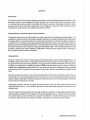
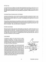
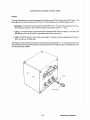
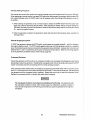
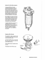
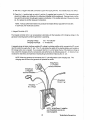
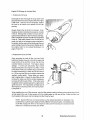
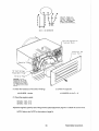
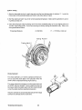
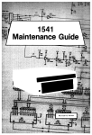
4.5 KW BCG Marine Gasoline Generator
Fresh Water Coolant Fill
20 Amp DC
Circuit Breaker
Exhaust Elbow
Lube Oil
Dipstick
Oil Pressure _ _
Switch
-u,", Battery Ground
Connection
Lube Oil FiltAr--Zinc Anloae~__
Starter with Solenoid
Heat Exchanger
Westerbeke Generators
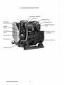
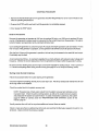
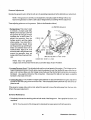
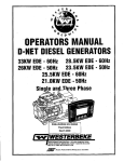
4.5 KW BeG Marine Gasoline Generator
Fuel Shut - off So,IAnoirl
Air Intake Flame Arrestor
with Choke
Control
Governor
L ..........- Sea Water Pump
Outlet
Lube Oil Drain Hose
1
Westerbeke Generators
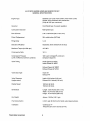
4.5 KW BeG MARINE GASOLINE GENERATOR SET
GENERAL SPECIFICATIONS
Engine Type
Gasoline, four-cycle, three-cylinder, fresh water-cooled
Vertical, in-line overhead valve mechanism
(8 bhp at 1800 rpm, maximum).
Governor
Hoof, flyball type, 5% speed regulation.
Combustion Chamber
Multi-sphere type.
Bore & Stroke
2.44 x 2.38 inches (62.0 x 60.5 mm)
Piston Displacement
33.4 cubic inches (.547 liter)
Firing Order
1-2-3
Direction of Rotation
Clockwise, when viewed from the front.
Maximum Torque (at 1800 rpm)
13.5Ibf-ft
Compression Ratio
10.0:1
Compression Pressure
(Limit of difference between cylinders)
198.1 psi (14.0 kg/cm2) at 400 rpm
2
(28 psi [2.0 kg/cm
Valve Timing
Intake Opens 320 BTDC
Intake Closes 52 0 ABDC
n
Exhaust Opens 560 BBDC
Exhaust Closes 280 ATDC
Valve Seat Angle
Intake 450
Exhaust 450
Valve Clearance
(engine warm)
Intake 0.010 inches (0.25 mm)
Exhaust 0.012 inches (0.30 mm)
Engine Speed
1800 rpm 60 he rtz.
1500 rpm 50 hertz.
Dimensions
Length: 26.50 inches (673.1 mm)
Width: i 8.34 inches (465.8 mrn)
Height: 23.44 inches (595.4mm)
Dry Weight
Approx. 3091bs (140.1 kgs)
Fuel Consumption
0.8 U.S. gph (3.02Iph) at full rated output (approximate).
Inclination
Continuous 140
Temporary 200 (not to exceed 20 min.)
Westerbeke Generators
8
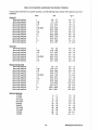
4.5 KW BCG SYSTEM SPECIFICATIONS
INTAKE SYSTEM
Carburetor (STD type)
Manual with butterfly shaped valve. single barrel
with U.S.C.G. approved flame arrester.
IGNITION SYSTEM
General
Battery ignition, 12-volts (negative ground),
distributor with points, ignition coil and spark
plugs.
Distributor
Conventional, contact-point type.
Spark Plug Thread Size
14 x 1.25 mm pitch (0.55 x 0.05 in.)
Spark Plug Type
Westerbeke part number 33805
(Always identify the generator model
when ordering parts. See page 5.)
FUEL SYSTEM
General
Conventional carburetor type with fuel pump.
Fuel
Regular or unleaded gasoline with an octane rating
of 89 or higher.
Fuel Pump
12-volt DC; lift capacity 5 ft (1.5 m)
Fuel Screens (on engine)
Reusable screen type (located at inlet to carburetor).
Air cleaner
Metal screen type - cleanable.
Air Flow (engine combustion)
18 clm (0.509 cmm) at 1800 rpm.
COOLING SYSTEM
General
Fresh water-cooled block,
thermostaticaiiy-controlled
with a heat exchanger.
Operating Temperature
130 -150'F (55 - 66'C)
Fresh Water Pump
Centrifugal type, belt-driven, 1.13:1.
Sea Water Pump
Positive displacement, rubber impeller, belt-driven.
9
Westerbeke Generators
4.5 KW BCG SYSTEM SPECIFICATIONS
Sea Water Flow, at 1800 rpm
(measured before discharging
into exhaust elbow)
3.75 - 4.0 U.S. gpm (14.19 - 15.14Ipm)
System Capacity (fresh water)
4.2 U.S. qts (3.9 liters)
LUBRICATION SYSTEM
General
Fully - Force fed type by Trochoid pump,
crankshaft-driven.
Oil Filter
Full flow, paper element, spin-on type.
Sump Capacity (not including filter)
3.0 qts (2.8 liters)
Operating Oil Pressure (engine hot)
50 - 70 psi (3.5 - 4.9 kgfcm 2)
Oil Grade
API specification of SE, SF or SG.
ELECTRICAL SYSTEM
Starting Battery
12-volt, 24 A-H, (-) negative ground
(recommended) (28 A-H in cold areas).
Battery Capacity
24 - 28 (ampere-hours)
DC Battery Charger
Integral controller 13-volt, 10 amp
(located in the AC alternator).
Starter
12-volt, 1.2 KW, Magneto engaging type.
DC No-Load Current
90 amp (max.) at 11.5 votts.
DC Cranking Current
100 -125 amps (engine cold).
Westerbeke Generators
10
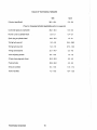
4.5 KW BCG SYSTEM SPECIFICATIONS
AC GENERATOR
General
Brushless, four-pole, revolving field.
Self exciting. Capacitor saturated field excitation.
Pre-lubricated, single-bearing design.
Reconnectable 120 volts or 120/240 volts,
single-phase.
Voltage
120 or 120/240 volts - 60 hertz
220 volts - 50 hertz.
Voltage regulation: ± 5% no-load to
full-load.
Frequency regulation: ± 3 hertz (5%)
no-load to full-load.
Rating (volts AC)
60 Hertz (1800 rpm)
120 volts
120/240 volts
37.5 amps
37.5/18.7 amps
50 Hertz (1500 rpm)
220 volts
16 amps
AC Circuit Breaker
To be rated at 120% of the generator's rated
amperage and voltage output.
Generator Cooling
Air Requirements, (60 hertz).
at 1800 rpm
225 - 240 cfm (6.4 - 6.6 cmm)
MQIE.: Increase air supply 15% for 50 hertz operation (1500 rpm).
Engine Combustion Air
Requirements, (60 hertz),
at 1800 rpm
18 cfm (0.509 cmm)
TUNE-UP SPECIFICATIONS
Spark Plug Gap
0.028 - 0.031 inches (0.70 - 0.80 mm)
Contact Point Clearance
0.017 - 0.018 inches (0.4 - 0.5 mm)
Timing
11' ± .5' BTDC at 1800 rpm
Dwell Angle
58 - 66'
11
Westerbeke Generators
INSTALLATION CHECKS
General
Since the crafts in which Westerbeke generators are installed vary in design, installation procedures will vary
according to your craft's specific design. The intent of this section is not to advise boatyards or installers
on procedures alreadywell-developed and well-understood. However, the owner/operator must realize there
are details of the installation which require periodic checks to ensure the best operating conditions for the
equipment and safe operating conditions for the personnel on board. Proper location and installation of the
gasoline generator in the vessel are of prime importance.
Factors in the installation that Il!1.lfi1 be considered are ventilation, to aid in cooling the generator end; to
provide air for engine combustion and to remove heat produced by the engine while operating; the exhaust
system, to properly discharge raw cooling water (sea water); to quiet the exhaust and to expel exhaust gas;
the cooling water supply; the electrical connections, both AC and DC, and a fuel system that will provide an
unrestricted fuel supply and properly filtered fuel to the fuel pump on the engine.
CAUTION
For safety reasons, the generator's engine is not filled with lubricating oil for shipment. Before
leaving the factory, however, each generator set is thoroughly tested with oil in its engine.
This testing, among other things, provides all internal parts with a coating of oil. This oil acts
as a preservative, providing reliable protection against corrosion for at least one year if the
generator is properly stored.
Inspection of Equipment
The generator is shipped from the factory securely mounted and properly crated. Accessory equipment is
shipped in a separate small box, usually packed within the generator's crate.
Before accepting shipment olthe generator set from the transportation company, the crate should be opened
and the contents inspected for concealed damage. If either visible or concealed damage is noted, you should
require the delivery agent sign "Received in damaged condition" on the proper delivery receipt. Also check
the contents of the shipment against the packing list and make sure that the proper notation is made if any
discrepancies exist. These noted discrepancies are your protection against loss or damage. Claims concerning loss or damage Il!1.lfi1 be made to the C1ll1ieL, not to Westerbeke Corporation.
Westerbeke Generators
12
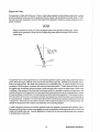
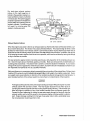
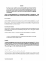
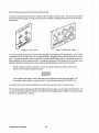
Rigging and lilting
The generator is fitted with lifting eyes. Rope or chain slings capable of supporting the generator's weight
should be attached to the eyes and the generator lifted by means of tackle attached to these slings. The lifting eyes have been designed to carry the full weight of the generator; therefore, auxiliary slings are not required or desired.
CAUTION
Slings must not be so short as to place significant stress on the generator's lifting eyes. Strain
placed on the generator's lifting eyes by the lifting sling must no! be in excess of 10' from the
vertical plain.
SLING LIFTING
ANGLE to4USI NOT
EXCEED 10'
LIFTING
EYE
ENGINE
The general rule in moving generators is to see that all equipment used is amply strong and firmly fixed in
place. Move the engine a little at a time and see that it is firmly supported. Eliminate the possibility of accidents by avoiding haste. Do not lift the generator by its crankshaft pulley. In certain situations it may be
necessary to lift the engine in positions other than the horizontal position. Certain situations exist by which
the engine must be lowered endwise through a small hatchway which cannot be made larger. Under these
conditions, if the opening of the hatchway is extremely small, tt is possible to reduce, to some extent, the
outside dimensions of the generator by removing external components such as the cooling system's piping,
the heat exchanger, certain filters, the mounting rails and other obstructive equipment. This accessory equipment should be removed by a competent mechanic and special care should be taken to avoid damage to
any exposed parts. In addition, be careful not to allow dirt from entering any opening created by the removal
of equipment. Removed parts should be returned to their respective position as soon as the generator has
cleared the obstruction and is ready to be positioned on tts mounting platform.
In case it becomes necessary to hoist the generator front-end upwards or generator-end upwards, the attachment of lifting slings must be done carefully to avoid the possibility of damaging the parts on which the
weight of the slings may bear. Special rigging work is best done by someone experienced and competent
in handling heavy machinery.
13
Westerbeke Generators
Generator Mounting - Location
The complete generator unit is mounted on lightweight rails by means of four flexible isolator mounts that
help preventthe transfer of vibration from the generator to the rails. Each generator mounting rail has several
1/2 inch bolt holes so bolts can be employed to properly secure the generator to its mounting platform.
These holes are on 15 inch mounting centers.
11/2"
MOUNTING HOLES)
The mounting location must be dry, above low-lying vapoi areas, and in an area where bilge water and water
from above cannot splash or drip on the generator or drive engine. The drive engine and generator ~
be accessible for minor servicing and repairs. Access for major repairs should be given consideration as
well. The generator set ~ be properly ventilated to provide fresh cooling air for the generator end, for engine combustion needs, and to remove heat produced by the engine while operating. The generator set
needs fresh cool air in whatever location in the vessel it is installed. Hot generator discharge air ~ be
removed from the generator area. The platform on which the generator and its mounting rails are located
~ be strong enough to support the generator during all angles of vessel operation.
Weslerbeke Generators
14
Exhaust System
~WARNINGi
Carbon monoxide gas is deadly! Carbon monoxide is a dangerous gas that can cause unconsciousness and is potentially lethal. Some of the symptoms or signs of carbon monoxide
inhalation or poisoning are listed below.
o Dizziness
o Intense Headache
o Weakness and Sleepiness
o Vomiting
o Muscular Twitching
o Throbbing in Temples
The generator should have ITS own separate exhaust installed so that the entry of sea water into the engine's
exhaust manifold and cylinders is prevented while the engine is not running, or while the vessel is under sail
or power in which case the vessel may experience heeling, backing down from following seas, or any other
conditions. Special attention 111J,!,Sl be taken to make certain the exhaust system is secure, tight and free of
leaks.
The sea water supply through-hull sea cock fittings 111J,!,Sl be of the flush-hull type. High-speed scoop types
or weedless scoop types must not be used, as they tend to encourage siphoning.
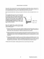
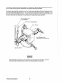
When a water lift type exhaust system is
used, the exhaust muffler should be mounted
as close to the engine as practical. The exhaust discharge should always drop
downward into the exhaust muffler. Loops in
the exhaust hose between the water-injected
exhaust elbow and the water lift muffler
should be avoided, as these will trap and hold
water.
".
VIlli
111~P
For installations where the exhaust
manifold/water-injected exhaust elbow is at
or below the vessel's water line, provisions
~ be made to install a siphon-break or a
vent in the sea water supply hose to the
water-injected exhaust elbow. This stops the
flow of sea water that runs through the sea
water cooling system from filling the exhaust
and engine cylinders when the engine is shut
down. This sea water supply hose ~ be
looped above the water line and the siphon-
\[~ VAHi
- lliA[NH
um!
lHUU~"""""~
lUll FlTlIH'
HHUUOl
(fhl$~
IYI><)
H!~t V~lEa
lII(
HfHOft aHRI _ _
break or vent installed in the high point of the
loop above the water line. This siphon-break
or vent111J,!,Sl always be above the water line
during all angles of vessel operation to
prevent siphoning. The vent, when used,
~ have its vent hose or tube routed so it
can remain above the water line and empty
of water when the engine is shut down. This
allows air to enter through this vent to
prevent siphoning.
15
Wes!erbeke Generators
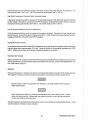
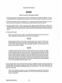
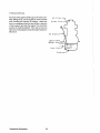
Exhaust Back-Pressure
The exhaust discharge hose !111.lfl1 be of adequate size and
minimal run to prevent excessive exhaust back-pressure.
Exhaust back-pressure should be checked before a generator is put into service. (Refer to the illustration.) Excessive
back-pressure will affectthe engine's performance which affects generator AC power output.
-Insulation
To measure for back-pressure, use a mercury manometer,
a pressure gauge, or a water column. A boatyard or marine
mechanic should have a manometer or a pressure gauge.
If the generator set does not have a tapped hole in its exhaust elbow, one must be drilled and tapped for a 1/8 inch
NPT fitting in the dry area of the elbow.
Exhaust
Elbow
Measure the engine's back-pressure at the exhaust elbow
while the generator is under a full-load.
,1,-...0.-"'-
Exhaust
Mercury
Manometer
Refer to the pressure specifications listed below.
\
A water column can be made by taking a clear plastic tube
and taping one end of the tube along a yardstick and fitting
the other end of the tube with a 1/8 inch NPT (National Pipe
Tap) pipe fitting.
Measure the engine's back-pressure at the exhaust elbow
while the generator is under a full-load.
Dimension A cannot exceed 39 inches of water.
Back pressure, as measured by a gauge instrument, should
not exceed the following specifications:
3 inches of mercury (0.104 kg/cm 2)
39 inches of water in a water column
(.099 kg/cm 2 at 4 C)
22 ounces psi
11/2 psi
~~~ Plug
0
\
Excessive back-pressure can be caused by a small diameter exhaust hose, a small muffler, sharp bends in
the exhaust hose, improper fittings, water pockets, and a high volume of water in the exhaust system due
to the length of the exhaust discharge hose. The use of elbows and fittings in the exhaust discharge hose's
routing should be limited since these will create flow restrictions and contribute to exhaust back-pressure.
The generator's exhaust system!111.lfl1 be separate from any other engine's exhaust system. Dry portions of
the exhaust system between the engine's exhaust manifold and the water injected exhaust elbow !111.lfl1 be
insulated to hold in the heat.
Westerbeke Generators
16
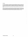
Dry stack-type exhaust systems
(shown to the right) l1lJ.lS1: be attached to the generator engine's exhaust manifold by means of a flexible
connector pipe. This system lIlll.&be
properly supported and insulated to
prevent water from entering into the
engine's cylinders. Provisions l1lJ.lS1:
be made for discharging the
engine's cooling sea water.
FLAPPI:II:
COV~III
---;P4'
iI
o-
M'"
.1
1/01#
l: • P _ s.
"1: .. 1:
.. :ITCH
OOWH
1/01
r::XHAUST
To
::tHeH
-
C <HUI
r:: N -
GAT leON
p
rR ..
;':2:i"F'F'II!'-",
LINE
Dl:SCHRRCE
P~R
rOOT
SEA WAT": ..
:tNTIlK": TI1RoUGH_
DRY STACK EXHAUST
Exhaust System Failures
When the engine's sea water is fed into an exhaust system so that the full stream of this water strikes a surface, erosion takes place. This erosion may cause premature failures. The proper design of either a water
jacketed or water injected ''Wet'' exhaust system to prevent this problem requires that the sea water inlet be
positioned so that the entering stream of sea water does not directly strike a surface. In addition, the velocity
of the entering sea water stream should be as low as possible, which can be achieved by having inlet fittings
as big in diameter as possible.
The best protection against carbon monoxide pOisoning is a daily inspection of the complete exhaust system. Check for leaks around manifolds, gaskets, and welds. Make sure exhaust lines are not heating surrounding areas excessively. If excessive heat is present, correct the situation immediately. If you notice a
change in the sound or appearance of the exhaust system, shut down the unit immediately and have the system inspected and repaired at once by a qualified mechanic.
Make sure there are no unnecessary objects suspended from any portion of the exhaust lines. Exhaust risers
installed off the exhaust manifold should not exceed 8 Ibs in total weight when rigidly constructed. Excessive weight could cause deflection or distortion of the manifold resulting in damage and/or internal leaks. Inspect insulated portions of the exhaust system to ensure there is no deterioration of the insulation.
CAUTION
Prolonged cranking intervals withoutthe engine starting can result in filling the engine-mounted
exhaust system with sea water coolant. This may happen because the sea water pump is
pumping sea water through the sea water cooling system during cranking. This sea water can
enter the engine's cylinders by way of the exhaust manifold once the exhaust system fills.
Prevent this from happening by closing the sea water supply through-hull shut-off, drain the
exhaust muffler, and correct the cause for the excessive engine cranking needed to obtain a
start. Engine damage resulting from this type of sea water entry is not a warrantable issue;
the owner/operator should keep this in mind.
11
Westerbeke Generators
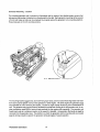
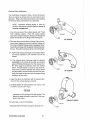
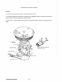
Exhaust Elbow Installation
The Westerbeke Corporation offers a 45'and 90'exhaust
elbow as well as an exhaust riser you can install on your
generator. Refer to the instructions below when installing
the exhaust elbow purchased for your generator.
NOTE: Fabricated exhaust elbows or risers attached to the exhaust manifold shall not exceed S
Ibs when unsupported.
1. Coat only one side of the exhaust gasket with '''High
Tack" adhesive sealant. Place this coated surface
against the exhaust manifold's exhaust port flange (the
gasket should stick to the flange without falling off).
GASKEI
CLAMP
45' ELBOW
2. Place the clamp over the elbow's flange. Place your exhaust elbow against the exhaust manifold's flange so
the exhaust manifold's flange rests snug against the exhaust elbow's flange with the gasket centered between
the two. Now slip the exhaust clamp over both flanges.
3. A. Tighten the clamp just enough so the exhaust elbow
can remain attached to the manifold and still be
rotated.
B. The exhaust elbow discharge 111.Ufl1 be directed
downward so the mixture of sea water and exhaust
gases will flow/fall downward into the exhaust muffler which 111.Ufl1 be positioned below the exhaust
elbow. There should be no loops or rises in the exhaust hose connected between the exhaust elbow
and the muffler, as these would trap water and possibly allow water to flow back into the engine during
starting or at shut down.
CLAMP
90' ELBOW
4. Adjust the elbow by rotating it until the desired alignment with the exhaust piping is acquired.
5. Carefully tighten the clamp between 2 to 3 Ib-It, or 24
to 35 Ib-in, or 0.27 to 0.41 kg-m.
CAUTION
Approach the 3 Ib-It torque limit with caution. The
clamp's threads will break if more than 3 Ib-It is applied to the clamp.
EXHAUST RISER
If a leak exists, correct it immediately.
* Manufactured by Permatex Company, Brooklyn, N.Y.
Westerbeke Generators
HI
CLAMP
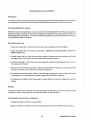
Fuel System
The generator lilll3.1 have its own fuel supply line; in other words, it lilll3.1 have its own fuel tank pickup tube
and primary filter/water separator. Do no\ tee off another engine's luel supply. Installations where the fuel
tank(s) are at or above the generator, with the fuel supply lines 10 the engine's carburetor routed below the
level of the fuel tank's top, lilll3.1 have a means of shutting off the fuel to the generator's engine when the engine is not running. This installation procedure helps guard against the possibility of gasoline siphoning
through the supply line into the engine through the carburetor, should the carburetor float needle valve stick
in the open position or not seat properly, or should the luelline rupture between the engine and fuel tank.
This (anti-siphon) shut-off valve can be electrically-operated (with a manual override) to open when the generator's engine is started, and to close when the generator's engine is shu! down. A manually-operated valve
can also be installed and should be operationallrom the generator's start/stop panel or from the vessel's
deck. Installations where the generator is located above the fuel tank(s), whereby the routing of the fuel
supply line to the generator's carburetor remains above the top level of the fuel tank, do not require this (antisiphon) shut-off valve. A manually-operated service shut-off valve should be located between the fuel pickup at the tank and the service shut-off valve located at the fuel connection to the generator.
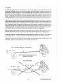
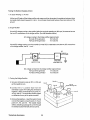
The two illustrations that follow were taken from the Coast Guard publication Fuel System Compliance
Guideline. These illustrations show basic fuel system layouts that incorporate anti-siphon protection.
All fuel lines should be routed and supported to prevent leaks from vibration and chaffing. The line should
be supported every 12 - 14 inches. Use as few connections as possible in the plumbing of these lines.
The fuel tank's vent should be located so that its discharge route cannot allow water to enter through to the
fuel tank(s). Moisture must not be allowed to accumulate in the vent's line.
FUEL liNE ALWAYS ABOVE FUEL TANK TOP LEVEL
FUEL TANK TOP lEVEL
'...- -
__---~~~~::::-::~=:--::-d
FUEl
TANK
NO ANTI-SIPHON DEVICE OR ELECTRICAllY
OPERATED VALVE NEEDED
NOT ACCEPTABLE
'"
FUEl
FUEL TANK TOP lEVEL
19
Westerbeke Generators
~
~
ANTI-SIPHON DEVICE OR ELECTRICALLY
OPERATED FUEL STOP VALVE
--- -;::-~~~~o;,.,;-;':;-::::-=:/~-7-=:=~F!U~El~-~T~":N-'~T~O:P~-lE~V~E~l~"7"~~i~~~~Ir-"","'--'
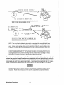
FUEL LINE BELOW FUEL TANK TOP LEVEL
ANTI-SIPHON DEVICE OR ELECTRICALLY OPERATED FUEL STOP
VALVE AT FUEL TANK WITHDRAWAL FITTING
FUEL
TANK TOP LEVEl
I
ANTI-SIPHON DEVICE OR ElECTRICALLY
OPERATED FUEl STOP VALVE
~ FUEL l~IH~E~"B~O~V~E~FU~E~l~T~AN:K::-:::~::~~~
----TOP LEVEl
FUEL LINE BELOW FUEL TANK
TOP LEVEl
ANTI-SIPHON DEVICE OR ELECTRICALLY OPERATED FUEL
STOP VALVE AT POINT WHERE FUEL DISTRIBUTION LINE
GOES BELOW FUEL TANK TOP LEVEL
NOTE: The use of mechanical spring-type check valves instead of a solenoid shut-off valve
is not recommended since these may tax the fuel pump's ability to draw fuel through a check
valve. A check valve can trap debris under its seat which inhibits the valve's ability to close.
In addition, if a check valve's cracking pressure is too high, this can contribute to vapor lock.
Should a mechanical type, spring-loaded check valve be used, it should be an adjustable type,
such as a Weatherhead #43 x 6. This adjustable type valve should be adjusted to have a
cracking pressure that will prevent siphoning when the generator is not operating but not so
excessive as to prevent the fuel pump from drawing fuel through the valve.
The installer should install an approved fuel filter/water separator in the fuel supply between the fuel
tank and the generator's engine to help remove contaminants in the fuel before the fuel reaches the
engine-mounted fuel pump and carburetor. Such contaminants can cause the failure ofthese system
components and such failures are not warrantable. Owner/operators are advised it is their responsibility to maintain filter/separators so that contaminants do not reach the engine's fuel system.
Gasoline leakage in or around the generator compartment is a potential cause of fire and/or
explosion. Repair leaks promptly and make sure the compartment is properly ventilated.
Westerbeke Generators
20
Oil Drain Hose
An oil sump drain hose is installed on the engine with the discharge end secured by a bracket at the front of
the engine. Oil may be drained from this hose by removing the cap and the discharge end of the hose from
the support bracket and lowering the hose into a container. The hose cap fitting is 1/4 inch NPT (National
Pipe Tap) and can be extended or have a pump added, by the operator, for easier removal of the old oil, if
desired.
Connecting Pressure Sensing Devices to Oil Galleries
Oil pressure sensing devices, such as senders and switches, must not be connected to an engine's oil gallery with the use of extended nipples or tees. The reason is simply that continued engine vibration causes
fatigue of the fittings used to make such a connection. If these fittings fail, the engine loses its oil pressure
and quickly seizes.
When additional sensing devices such as switches or sensors need to be installed that function on engine
oil pressure, these devices !11.LlS1 be bulkhead-mounted and connected to the oil gallery using an appropriate
grade of lubricating oil hose. Any fittings used to connect the hose to the gallery must be of steel or malleable iron composition. Brass must not be used for this application.
Sea Water Intake System
Make sure the Intake system (sea water cooling system) is in proper order. Check that the hull inlet, sea
cock and strainer are unobstructed. Sea cocks and strainers should be at least one size greater than the
inlet thread of the sea water pump. The strainer should be of the type that may be withdrawn for cleaning
while the vessel is at sea and should be mounted below the water line to ensure self-priming. I nspect the
sea water lines to make sure there are no collapsed sections, which would restrict water flow. Make sure
there are no air leaks at any of the connections.
Cooling System
The generator's engine is fresh water-cooled by an enginemounted heat exchanger. Sea water is used as the heat
exchanger's cooling medium. Sea water is pumped into the
exchanger by a sea water pump and is then injected into the
exhaust for discharge, carrying with it the heat removed from
the engine's fresh water cooling system.
Sea water should be supplied to the sea water pump through
a flush-type through-hull fitting using a wire-reinforced hose
between the through-hull fitting and the sea water pump. This
sea water should be directed through a visual-type sea water
strainer and then delivered to the pump. Hoses routed from
the through-hull fitting to the strainer and to the sea water pump
should be wire-reinforced to prevent the hose from collapsing
during the generator's operation (suction from the pump may
collapse a non-reinforced hose). Sea water strainers should be
mounted at or below the water line to make sure the strainer
and line remains primed after shutdown.
21
liB-in iNCH
DEFLECT ION AT
LONliEST SPAN
Westerbeke Generators
CAUTION
Do not use a scoop or weedless scoop-type through-hull fitting as a means of supplying sea
water to the generator. Water pressure against this type fitting, while the vessel is under way,
can push sea water past the sea water pump's impeller into the generator's exhaust system,
filling it and the engine's cylinders as well. Flush-type, clear, through-hull fittings are recommended and should be located on the hull so as to be below the watertine during all angles
of boat operation.
The use of common-type street elbows is not recommended for plumbing the sea water circuit. These
generally have very restrictive inside diameters. Machined fittings with true inside diameters are preferred.
Electrical System
The electrical system should be checked to make sure all wires and harnesses are property tied down with
clamps or plastic ties and that all wiring harnesses are supported at intervals close enough to prevent chafing from vibration. Check to make sure all engine harness connections are tight and that they are made to
the appropriate terminals. Also, ensure that these terminals are not the recipients of bilge water or water
from leaky hatch covers or corrosion will result.
DC Electrical Connections
A tagged common ground stud for the negative (-) DC terminal connection is found at the bell housing of the
generator, next to the starter, in the form of a threaded grounding stud. The DC battery ground should be
connected at this stud.
Connect the battery's positive (+) connection to the starter solenoid tagged for this connection.
CAUTION
To avoid an overcharging condition and a possible equipment failure, do not disconnect the
DC battery source while the engine is running.
Grounding
The generator set ll!.f.mt be grounded to comply with United States Coast Guard regulation 33 CFR-183 which
specifies that a common conductor be connected between the generator set and the vessel's main propulsion engine's grounded starter motor circuit. This conductor (the common ground) prevents accidental passage of cranking current through fuel systems and smaller electrical conductors common to the engines.
This conductor ll!.f.mt be the same size as the largest battery cable.
Automatic Shutdown
High Exhaust Temperature Shutdown Switch (normally closed)
An exhaust temperature switch is located on the exhaust elbow. This switch will open and interrupt the DC
voltage to the ignition coil (which turns OFF the engine), should the switch's sensor indicate an excessive
Westerbeke Generators
22
exhaust temperature (an inadequate supply of sea water coolant causes high exhaust temperatures). This
switch opens at 260 - 270' F (127 -132' C) and resets at approximately 225' F (107' C).
High Water Temperature Shutdown Switch (normally closed)
A high water temperature switch is located on the thermostat housing. This switch will open and interrupt
the DC voltage to the ignition coil (which turns OFF the engine), should the fresh water coolant's operating
temperature reach approximately 205' F (96' C). This switch resets at 195' F (107' C).
Low Oil Pressure Shutdown Switch (normally open)
A low oil pressure shutdown switch is located off the engine's oil gallery. The switch's is kept closed by engine oil pressure. Should the engine's oil pressure fall to 10 - 15 psi, the switch will open interrupting the DC
voltage to the Ignition coil (which turns OFF the engine).
High RPM Shutdown Switch
An overspeed shutdown switch shuts OFF the generator set by grounding out the ignition system should the
engine's speed reach approximately 2175 rpm. Reset this switch by momentarily depressing the STOP
switch. (Make sure the cause of the engine overspeed shutdown is corrected.)
Generator (AC Output)
Make sure that the AC output connections within the generator's distribution box are tight and in accordance
with the specific AC Load Connections diagram found later in this manual. (See the "BC GENERATOR" section of this manual, page 51.)
Batteries
Make sure the positive ( + ) battery connection is connected to the battery connection of the starting solenoid.
The negative (-) battery connection should be connected to the system ground (the engine block).
IWARNINGI
Do not smoke or allow an open flame near batteries. Lead acid batteries emit hydrogen, a
highly-explosive gas.
IWARNINGI
When servicing the battery or checking the electrolyte level, wear rubber gloves, a rubber
apron, and eye protection. Battery acid may splash on the skin or into the eyes inadvertently when removing the electrolyte caps.
Check the battery's electrolyte level and specific gravity to ensure maximum engine starting efficiency. Make
sure the battery's terminals are clean and tight.
23
Westerbeke Generators
Ventilation
The ventilation requirements of the generator sets include the following: combustion air is required for the
engine cylinders; cooling air is required for the generator end and also for removing the heat produced by
the generator's engine during operation; and ventilating air is required to clear the bilges below the generator, as well as the compartment in which the generator is located, of potentially toxic and flammable gasoline
vapors.
Keep in mind that hot air rises, so heated air should be removed from the upper area of the generator compartment and cool fresh air should be directed to the lower areas of the compartment. Ventilation should
be accomplished with the aid of blowers especially when the vessel is not undelWay. Refer to the "SYSTEM
SPECIFICATIONS" section of this manual for the airflow requirements of the generator set, page 11.
Westerbeke Generators
24
DESCRIPTION OF ENGINE CONTROL PANEL
General
The engine-mounted control panel is equipped with an ON switch, a START switch, and a STOP switch. The
panel also has two fuses to protect the DC circuit. The three switches serve the following functions:
1. ON Switch· The ON switch provides power to the START circuit. This switch also bypasses the protective oU pressure shutdown switch until the engine's oU pressure reaches 10 - 15 psi.
2. START· The START switch energizes the starter's solenoid which cranks the engine. This switch will
not operate unless the ON switch is depressed and held at the same time.
3.
~
The STOP switch is used to stop the generator. This switch must be depressed until the generator comes to a complete stop.
The engine mounted control panel has two protective fuses incorporated in it. A 15 amp fuse protects the
start circuit and an 8 amp fuse protects the operating circuitry on the engine and any remote start/stop panel
or instrument panel installed.
25
Westerbeke Generators
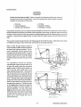
Optional Remote Instrument and Remote Start Panels
An optional remote instrument panel is available, which includes starting controls. This panel also includes
a water temperature gauge, oil pressure gauge, battery voltmeter, operating hourmeter and start-stop control switches.
REMOTE INSTRUMENT PRNEL
REMOTE START PANEL
The remote instrument panel has with it two sending units to be installed on the engine block. One, a water
temperature sender and the other, an oil pressure sender. Plugged ports for each are located on the engine. The water temperature sender is installed in the thermostat housing and the oil pressure sender is installed adjacent to the oil pressure switch. Use sealing compound on the threads of both senders when
installing. Electrical connections for each sender are tied off adjacent to each sender's location.
NOTE: The blue colored connection is for the oil pressure sender and the tan colored connection is for the water temperature sender.
IWARNINGi
When installing the optional remote start panel or the optional remote instrument panel, it is
the installer's responsibility to comply with U.S. Coast Guard Standards 33 CFR PART 183.
An optional remote start panel is available for controlling the generator from a remote location.
Remote start panels include a green LED which lights when the engine runs at approximately 600 rpm. The
purpose of the LED is to alert the operator to release the starter toggle switch in addition to continue indicating that the generator set is running.
Westerbeke Generators
26
PREPARATIONS FOR STARTING
This section of the manual provides the operator with preparation, initial starting, break-in, starting (cold or
warm), and stopping procedures. Follow the procedures as presented, for the conditions indicated, and
your Westerbeke generator set will give you reliable performance and long service life.
Take the steps described below in starting your engine for the first time or after a prolonged shutdown or layup.
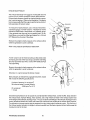
Fill your engine with oil up to but not over the upper limit
on the dipstick (the installation angle of your generator
set may have an effect on the dipstick reading). Select a
readily available lubricating oil with an API specification
of SE, SF or SG and an SAE number suitable for the
temperature in your operating area (see page 48). For the
quantity of oil needed in your generator's engine, refer to
the "SYSTEM SPECIFICATION" section of this manual,
page 10 for the 4.5 't0N BCG.
UPPER LIMIT
(H()RI-IRL
LE'UEL)
LOWER LIMIT
Each unit is supplied with a coolant recovery kit (part
#24977) as standard equipment which !111.&1 be installed
and the following applies:
A. Remove the pressure cap from the engine's exhaust manifold and slowly fill the engine's cooling system with a mix1ure of water and antifreeze suitable for your temperature zone. (See the "COOLING SYSTEM" section of this manual, page 42.) Replace the pressure cap on the manifold.
B. Make sure the plastic recovery tank is properly mounted near the unit (with the bracket provided) in a
location where tt can be monitored and filled easily (see page 43). The recovery tank should be mounted
al manifold level or above, however, if the installation does not permit this, mounting it below the manifold
is permitted.
C. Coolant should be added to the plastic recovery tank after the engine has been filled and started. After
its operating temperature has been reached, make sure all air is expelled out of the engine's manifold
and the engine's cooling system. With the manifold filled completely and the pressure cap installed, fill
the plastic recovery tank half full. Monitor this recovery tank daily and add coolant as needed.
Fill the fuel tank with unleaded or leaded gasoline that has an octane rating of 89 or higher.
27
Weslerbeke Generators
STARTING PROCEDURE
~WARNINGi
Carbon monoxide exhaust gas is deadlyl
1. Ventilate the generator compartment for a minimum of 5 minutes prior to starting the generator. The ventilating blowers remove potentially explosive gasoline fumes from the generator compartment and bilge.
2. Depress the ON switch and hold it depressed for 5 to 15 seconds to make sure the fuel system on the engine is primed to the carburetor. Continuing to depress the ON switch, proceed to step #3.
3. Depress the START switch. When the generator starts, release only the START switch. Keep the ON
switch depressed for a few seconds longer. (Keeping the ON switch depressed bypasses the oil pressure
shutdown circuit until the oil pressure rises enough to close the switch internally and maintain the ignition
circuit.)
4. Release the ON switch.
NOTE: The carburetor has an electric choke solenoid that closes the choke'when the start
switch is depressed, applying positive choke function during starting.
CAUTION
When starting the generator, all AC loads, especially large motors, should be switched OFF
until the engine has come up to speed and, in cold climates, starts to warm up. This precaution will prevent damage caused by the unanticipated operation of AC machinery and will
prevent a cold engine from stalling.
CAUTION
Prolonged cranking intervals without the engine starting can result in filling the enginemounted exhaust system with sea water coolant. This may happen because the sea water
pump is pumping sea water through the sea water cooling system during cranking. This sea
water can enter the engine's cylinders by way of the exhaust manifold once the exhaust system fills. Prevent this from happening by closing the sea water supply through-hull shut-off,
drain the exhaust muffler, and correct the cause for the excessive engine cranking needed to
obtain a start. Engine damage resulting from this type of sea water entry is not a warrantable
issue; the owner/operator should keep this in mind.
Once the engine starts, check instruments (if instruments are installed) for proper oil pressure and banery
charging voltage. Never attempt to engage the starter while the engine is running. Apply a light load to the
generator and allow the engine's operating temperature to come up to 130 - 150' F (55 - 56' C) before applying any heavy loads.
NOTE: Some unstable running may occur in a cold engine, but this condition should smooth
out as the operating temperature is reached (130 - 150' F [55 - 66' C]) and when a load is applied to the generator.
Westerbeke Generators
28
Remote Starling Procedure
The remote start panel is the same as the engine-mounted start panel except that it has a green LED light.
When starting at a remote location, the green LED lights when the generator is running at approximately 600
rpm, which indicates when the START switch can be released, since the starting of the generator may not
be audible.
A. When starting the generator set at a remote location, release the START switch when the green LED
lights, but continue depressing the ON switch. After releasing the START switch, continue holding the
ON switch until the oil pressure is sufficient to close the oil pressure safety switch, providing the normal
B + path to the ignition system.
B. After the generator is started, the generator's starter will not crank until someone again operates the
ON switch first.
Remote Stopping Procedure
To STOP the generator, depress the STOP switch, which opens the normally closed B + path for voltage to
the engine's ignition circuit. The STOP switch llJ.l.lS1 be held open until the generator comes to a complete
stop. Remote start panels may be connected to the generator set as indicated. A jumper has to be removed
between the T -1 and T -2 connections at the panel connection terminal board. (Refer to the wiring diagram
in the "ELECTRICAL SYSTEM" section of this manual, page 40.)
Overs peed Shutdown
Should the generator shut down from an overspeed condition, the overspeed circuit llJ.l.lS1 be reset before
attempting to restart the generator. Resetting the overspeed switch is done by simply depressing the STOP
switch momentarily and then proceeding with the normal starting procedure.
If the overspeed switch itself is faulty and resetting it by depressing the STOP switch will not reset the circuit,
lift the T-1 coil connection from the switch and tape the end of the T-1 wire with electrical tape. Do not operate
the generator with the overspeed switch bypassed. Bypass this circuit only to test the overspeed circuit.
Replace the overs peed switch to maintain this safety circuit's integrity.
The overspeed shutdown must always be installed and functioning. Any tampering with
the overs peed shutdown module, which would cause it to malfunction, could be a cause of
injury should the generator's belt-driven governor fail and cause the generator drive engine to
overspeed.
29
Westerbeke Generators
STOPPING PROCEDURE
1. Remove the AC electrical load from the generator and allow the generator to run for 3 to 5 minutes to stabilize its operating temperatures.
2. Depress the STOP switch and hold it until the generator is completely stopped.
3. Now release the STOP switch.
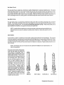
Break-In Precautions
Because the generator set operates at 1800 rpm to produce 60 hertz, or at 1500 rpm to produce 50 hertz,
control of the generator's engine break-in is governed by the current drawn from the generator. Do not attempt to break-in your generator set by running it without a load.
Upon starting the generator set, check for proper AC oU1put and engine operation; both are related. For the
first 10 hours of the generator's operation, run the generator set between 20 and 60 percent of full-load.
After the first 10 hours of the generator's operation, the load may be increased to the rated full-load output.
Periodically vary the load.
Avoid overload at all times. An overload is signalled by a smoky exhaust, with reduced output voltage and
frequency. Monitor the current being drawn from the generator and keep it within the generator's rating.
Be aware of motor starting loads and the high current draw required for starting motors. This is upward of
3 - 5 times the amperage draw during normal running (see page 57 for an "Amps for Starting" chart).
Starting Under Normal Conditions
Follow the procedure below for roU1ine starting of the generator:
Check the engine's lubricating oil level prior to each day's use. Add oil as needed and maintain the oil level
at the high mark on the dipstick.
Check the coolant level in the plastic recovery tank.
NOTE: Excessive loss of fresh water coolant from the plastic recovery tank indicates a cooling system leak. Check the entire cooling system, as well as the coolant recovery system,
and pressurize the system to locate the leak. In cases of excessive coolant loss, the system
l11.US1 be refilled as outlined under the "PREPARATIONS FOR STARTING" section of this
manual, page 27.
Visually examine the unit; look for any abnormalities and correct them as needed.
Check to make sure there is sufficient fuel in the tank and examine the filter/water separator bowls for contaminants. Clean and drain the bowls as needed.
Westerbeke Generators
30
Start the generator, following the procedure outlined in the "STARTING PROCEDURE" section, page 28, and
allow the engine's operating temperature to reach 130 -150° F (55 - 66° C) before placing the generator under
a heavy load.
Starting Under Cold Conditions
Under extremely cold temperatures, the following conditions can occur. Follow the instructions listed below
when operating your generator set in cold weather.
Lubricating oil turns viscous - Make certain that the lubricating oil used conforms with the ratings for the
prevailing atmospheric temperature. Refer to the "LUBRICATION SYSTEM" section of this manual, page 48,
for an atmospheric/oil viscosity specification table.
Voltage across battery terminal drops - Make certain that the battery is fully charged to minimize voltage
drop across the battery terminals.
31
Westerbeke Generators
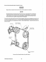
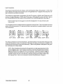
CARBURETOR AND FUEL SYSTEM
Gasoline
Use unleaded or leaded gasoline with an octane rating of 89 or better.
I n cold weather particularly, water vapor is produced by condensation when air is present in the fuel tank.
Keep fuel tank(s) full and completely free of dirt and water.
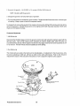
The carburetor is a single barrel, down-draft type with a cleanable metal screened air intake filter/spark arrestor.
Screened
Cleaner
. Choke Solenoid-ReInoved
Throttle Stop
(Enlarged View)
Idle Mixture
Westerbeke Generators
32
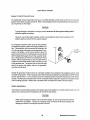
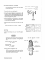
Optional Fuel Filter/Water Separator
A primary fuel filter of the water
separating type lI1.LI.iit. be installed between the fuel tank and the engine.
This is to remove water and other contaminants from the fuel before they can
be carried to the fuel system on the engine where they can cause unwanted
engine stoppage and damage to the
fuel system equipment on the engine.
Most installers do include with the generator installation package a type of filter/water separator for they are aware
of the problems contaminants in the
fuel can cause - all of which are not
warrantable through Westerbeke.
A typical fuel filter/water separator is illustrated at the right. This Is the
Raycor Model 110 and is approved for
use with marine gasoline products. A
filter/water separator of this type
should be part of your installation's
fuel system.
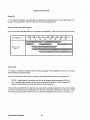
Replacing Filter Elements
The generator model covered by this
manual has one fuel filter screen referred
to as the inlet filter screen.
To remove the filter screen, unscrew the
filter plug and remove the fuel filter
screen behind the plug.
Clean the filter screen or replace it with a
new one.
Periodically check this filter screen.
33
Westerbeke Generators
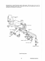
The engine mounted fuel pump requires little or no maintenance. Ensure fuel being supplied to this pump
is free of water or other types of contaminants that will hinder the pumps operation.
Periodically check the fuel connections to and out of the pump and make sure that no leakage is present
and that the fittings are tight and secure. Also, check that the DC electrical connection supplying 12 volts
DC to the pump is clean, tight and secure. The DC ground connection at one of the pumps mounting bolts
should be clean and well secured by the mounting bolt to ensure proper pump operation.
Fuel Supply (out)
to Carburetor
12 V DC (+) Connection
Fuel Supply (In)
(Insta.ller's Connection)
Ground Wire
IWARNINGI
Fuel leakage at the fuel pump or its connections is a fire hazard and should be corrected.
Make sure proper ventilation exists whenever servicing fuel system components.
Westerbeke Generators
34
ELECTRICAL SYSTEM
Engine 12-Volt DC Control Circuit
The engine that drives the generator end has a 12-volt DC electrical control circuit, as shown on the wiring
diagram which follow on pages 38 and 39. Refer to these diagrams when troubleshooting or servicing electrical components on the engine.
CAUTION
To avoid damage to the battery's charging circuit, never shut off the engine's battery switch
while the engine is running.
However, shut off the engine's battery switch to avoid electrical shorts when working on the
engine's electrical circuit with the engine stopped.
An overspeed shutdown switch shuts off the generator
set should the engine's speed reach approximately 2175
rpm. This shutdown circuit consumes 25 milliamps (.25
or 1/4th of an amp) at all times once the generator is connected to its battery. As this only amounts to about 18
amp-hours in a month, it is unnecessary to be concerned
with this slight discharge during normal seasonal operation. If the generator set were to be unattended for many
months, the two easiest ways to stop this slight drain is
to first turn off the main battery switch providing 12 volts
to the generator set. The second way to stop this slight
drain is to remove the ignition fuse on the generatormounted control panel.
EJ
OMP
IGNITION
FUSE
Should the generator shutdown from an overspeed condition, the overspeed circuit ~ be reset in order
to restart the generator. If the overspeed switch itself is faulty and resetting it by depressing the STOP switch
will not reset it, lift the T-l coil connection from the overspeed switch and tape the terminal end with electrical tape. Do not operate the generator with the overspeed switch bypassed. Bypass the overspeed switch
only for testing purposes. Replace the overspeed switch to maintain this safety circuit's integrity.
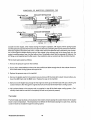
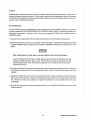
Battery Specification
The minimum recommended capacity of the battery used in the engine's 12-volt DC control circuit is 24 - 28
ampere-hours (minimum) ior the generator set covered by ihis manual.
CAUTION
When quick-charging the battery with an external charger, be sure to disconnect the battery
cables from the battery. Leaving the charging circuit connected while quick-charging will
damage the diodes in the integral controller's circuitry.
35
Westerbeke Generators
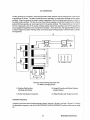
Testing the Battery Charging Circuit
1. AC Stator Winding: 0.14 Ohm
Lift the two AC leads off the bridge rectifier and measure with an ohmmeter the resistance between these
two leads which should measure 0.14 ohm. No continuity should exist between these two leads and the
ground.
2. Bridge Rectifier
Normal AC voltage running to the rectifier (while the engine is operating at 1800 rpm) is measured across
the two AC connections on the bridge rectifier. (See the illustration below.)
AC voltage running to the bridge rectifier (approximate):
No-load off the generator
16.0vollS AC
Full-load off the generator
17.5 volts AC
Normal DC voltage running out of the rectifier (in volts DC) is measured across the two DC connections
of the bridge rectifier; that is, + and - .
AC
DC
CHARG
+
AC
-I>I-
LC.
BRIDGE
RECTIFIER
INTEGRAL
CONTROllER
DC voltage running from the bridge rectifier (approximate):
No-load off the generator
17.0 volts DC
FUll-load off the generator
18.5 volts DC
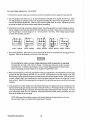
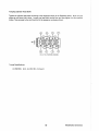
3. Testing the Bridge Rectifier
Point .,2
A. Set your ohmmeter's scale on RXI (+ DC) and
set the needle to zero.
Point tfS
(Rectifier Mounting Hole)
B.Connect the (+) positive lead from the
ohmmeter to point #4. Taking the ohmmeter's
negative (-) lead, momentarily touch points #i,
#2, #3, and #5. The ohmmeter should register
no deflection for any of the points touched.
_Point 113
C. Remove the positive ( + ) lead from point #4 and
connectthe negative (-) lead to point #4. Touch
points #1, #2, and #3. The needle should
deflect, indicating a passage of current through
the diodes located internally at these points.
Westerbeke Generators
36
D. With the (-) negative lead still connected to pOint #4, touch point #5. The needle should not deflect.
E. Place the (+) positive lead on point #1 and the (-) negative lead on point #3. The ohmmeter again
should not register any deflection (no deflection indicated infinite resistance). Reverse these connections and the ohmmeter should again register no deflection. If the rectifier fails any of the previous tests
(A - E), replace the rectifier because it is defective.
NOTE: Various style/model meters may produce test results directly opposite from tests B-E.
In such tests, the results are as above.
4. Integral Controller (I.C.)
The integral controller (I.C.) is an encapsulated, solid-state unit that supplies a DC charging voltage to the
generator's starting battery while the generator is operating.
Charging Voltage:
Charging Amperage:
13.0 -14.0 volts DC
0 - 10 amps DC
A separate group of stator windings supplies AC voltage to a bridge rectifier which converts the AC current
into DC current to supply the I.C. unit. The I.C. unit senses the needs of the starting battery and supplies a
DC charge when one is needed. If you suspect that the I.C. unit is faulty (that is, if the battery's charge is
low), check the charging circuit's components and performance by following steps #1 - 3. Check all connections for cleanliness and tightness including the ground before replacing the I.C. unit.
NOTE: When the generator is first started, the I.C. unit will produce a low charging rate. This
charging rate will rise as the generator is operated for awhile.
WMeIYeliow
( +) Positive
Terminal of Rectifier
Whhe/Green
(-) Negative
Terminal of Rectifier
White/Black
Ground ~
White/Red
D.C. Charge
NOTE: White/Green (-) negative
and White/Black ground are
Interchangeable.
37
Westerbeke Generators
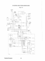
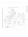
DC CONTROL CIRCUIT WIRING DIAGRAM #38028
Page 1 of 2
E!J,.LlAST
-~+
+1' PURPU
''-<
HH~"'ST
TEWP
SWI1CH
FU5E
-- -----
Westerbeke Generators
38
---
SA"'?
- ---
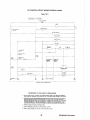
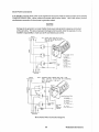
DC CONTROL CIRCUIT WIRING DIAGRAM #38028
Page 2 of 2
SCHEMATIC
DIAGRAM
12 VDC BATTERY
1--,------------'---1IIIiIf--I.___
r---
.---
'-~-l
:
!
\
I CIRCUIT 8REAKER
d:
I
-~ I
.Of-----~jll~.
STARO'
''".'.''.'.''
__________. ______________..,
•
._
20AI.IP
J
I
BATTERY r-HAR{;[R
CHOKE SOl-EI'lOID
0
I
CARe SOLENOID
PUMP
'"
I
BALLAST
+ RESISTOR
+
COIL
DISTRIBUTOR
1
..L OIL PRESSURE
f"'"
EXHAUST TEt.4P
~
SW""
STOP
SWITCH
WATER TEMP.
SWITCH
FUSE
,
~--
15 AMP
-- --
,,
-r-~
,
KI
~-~OIL PRESSURE
" "
'SENDER
jlOPTlQNALi
NOTE ;,
- - - - - 1-------
~"1 WATER TEI.IP
l"eo,,,,,,
,
: SENDER
NOTE
FUSE
8"MP
n
,
-,
,
,
,
""
'--- -
" "
OVERSPfEO SWITOI
ON SWITCH
I T81-1
I
~
+
,
HOJR METEll
START SWITCH
C/
1
TBI 3
T81-4
GaUleK CONNECTSlj
"" "
T81-
REMOTE PANEL CONNECTiONS
RESPONSIBILITY FOR SAFETY REGULATIONS
BATTERY CHARGER CAUSES A 9"'0 ·DllArl'< AND DVERSPEED MODULE CAUSES A t5mo DRAfN WHEN GENERATOR
IS NOT OPERATING THEREFORE WHEN LEAVING BOAT FOR AN EXTENDED 1'£1<100, DISCONNECT THE BATTERY.
SENDERS SUP?.JED WITH OPTIONAL INSTRUMENT R<>.NEL.
MINIMUM R£CDMMENDEO WIRE GAUGE TO REMOTE PANEL IS No. 14 AWG
REMOVE JUMPER BETWEEN TBI-I AND TBI-2 WHEN USING REMOTE
39
PANEL
Westerbeke Generators
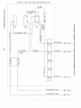
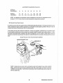
OPTlO/0AL ~'EMOTE START PAiJEL (REAl< VIEW) P. iJ. 33703
~-------
-----------------~
I
"110 RED
::;:
m
I
~IZ YEUvJ/RED
1
2I-
STRIPE
m
~
c---+l0<t
0<D
$"
.:);l;<~
Cl
~
<D
"
<D
~
o
iil
o
~/ZRED
START
STOP
ON
""
~
~
"tI
/W/PUR
C, TRIPE
-i
(5
Z
~
<l'IZ PED/W/PUP STRIPE
:t>
r-
::0
~
G~
~
m
s:
~~
""~
'C:JV)
" eI
""
::)
~
~
......
~
I
1
1"14 RED/W/PW2
~ TO T51- Z
~
"12. YEL/W/PED
OJ
STRIPE
"
e
e
T3-1
I
Ie
"Ib PURPLE
01
T3-Z.
-q
-J
OJ
~I
I #14 P U R P L E . TO T51-4
Z
m
r-
T4.i'
:§
2:!
eT4·3e
Cl
o
i>
:t>
s:
e e
'II:
T4A
lee I
'"'"o
~
TO TBI-S
"/4 YEL/W/i<ED S T R I P E .
TO TBI-3
iF 14 REO/W/PUR
TO TBI- I
T4-5
+_ _ _ _ _ _ _ _ _ _ _
"tI
:t>
Cl
::0
'"
_____
~
z
e
e
'-J
L
(J)
::0
-i
T4·1
Cl
w
L _
~
m
1'/4 BLACk
I
I
I
- - - - -- - - - - - - - - - - - - - - '
STRIPE
•
.
'"
('!
o
k'EMOTE
r·~
,,
"
I
00
I
CO
M
I,'
'!to
~IZ
::;;
(!!
«
I
C
YEL/wIRED STRIPER
u
I~r-
····j
z
Il'/Z
a:
TO T81-Z. ,
I,14RED
/'w'/PUR
I
TOTBI-4 ....... __
: 1f14PURPL£
w
QUICK. COJ.)tJEC T.....
TERMIIJAL
w
b::;;
TERMiNAL
0::
jl4HLACK
I
TO TSH
II
BT440
1 .-"'I
I
'lbTAN
E
rJ-'
I
:z
I
I
I
...J
Ii:
o
~:~t=J=::::
I,
TOTBI-5 •
V·,,,
~
f4 5
;;J
BLACK
•.
I
j
STRIPE
...
I '14 Y~E5;L!c/~"'/~R~£~D~_ _ _ _ _ _ _ _ _ _ _ _ _ _ _ _ _ .
TOTBI- 3
---r-;rflpE
I
L
T3-2
"I
I
I~---t.-----t-._.
1/14 REDM/PUR
i
._~~BLACK
CD
I
QUICK COWJEC T ._._+-~11JAIJ ___
w
«
o
~.~~.~~_
: If 14 L
I
f-
en
:z
I
I
I
'"
€
~
;::
Q)
_______
~
Ii'IIO PURPLE
I
Z
::;;
-'"
Q)
~"~PUR~'~ __._ ._:~
YEL/wl REO STRIPE
I"-12. REDM/~!d...~,?!r<IPE.--<-._,-___..~._..._._.
T4-1
-8 0
STRIPE
W
:J
0::
(!!
t/2 RED/WjPUf? 5TRIPE
§:
f-
Q)
cQ)
I
I
WATER TEMP
Oil PRESSURE
L.:::J/kI/PUQ
O/J
STRIPE
E
I
I
I
0
jULtil'12"ED
I
START
STOP
(!!
~"'lbRE!2
~
,--
«
0::
:z
«
a.
1
';!EO/W/PuRPLE STRIPE
I
'"'"o
...J
I_I::!._~TR~M~~~_!-,A_~E~~ R~A ~_yl~~)
~i~BLA~_
"'
is'
~
~
«
I
~
~
"'
~I
AI
...
~
~~
t~
--
-j
0,,- •.. .
1-10URS
VOLTS
"I'=> PURPLE
~---.='...=.'.= ..- - - . - . - . - -
I
I
I
I
I
I
_____ J
COOLING SYSTEM
Description
Westerbeke marine gasoline engines are designed and equipped for fresh water cooling. Heat produced in
the engine by combustion and friction is transferred to the fresh water which circulates throughout the engine. This circulating fresh water cools the engine block and its internal moving parts. The heat is transferred
externally from the fresh water to sea water by means of a heat exchanger, similar in function to an automotive radiator. Sea water flows through the tubes of the heat exchanger while fresh water flows around the
tubes; engine heat transferred to fresh water is conducted through the tube walls to the sea water which is
pumped into the exhaust system and discharged overboard. In basic terms, the engine is cooled by fresh
water, the fresh water is cooled by sea water, and the sea water carries the transferred heat over the side
through the exhaust system. The fresh water and sea water cirCUITS are independent of each other. Using
only fresh water within the engine allows the cooling water passages to stay clean and free from harmful
deposits. The two independent circuits and their components are discussed in the following paragraphs.
Fresh Water Circuit
NOTE: Refer to paragraphs A and B in this section on the recommended antifreeze and water
mixture used as the fresh water coolant, and for information on filling the fresh water system.
Fresh water is circulated through the engine by a belt-driven circulating pump, absorbing heat from the engine. It then passes through the thermostat into the exhaust manifold, then to the heat exchanger where it
is cooled, and then is returned to the engine block through the suction side of the fresh water circulating
pump. When the engine is started cold, external fresh water flow is prevented by the closed thermostat (although some fresh water flow is bypassed around the thermostat to prevent the exhaust manifold from overheating). As the engine warms up, the thermostat gradually opens, allowing the engine's fresh water coolant
to flow unrestricted to the external portion of the cooling system.
A. Fresh Water Coolant (Antifreeze) Mixture.
A freshwater and antifreeze mixture should be used year-round. Water, when it freezes, expands SUfficiently to split the heat exchanger and crack the engine block. A water/antifreeze mixture of proper concentration will prevent freezing and promote better heat transfer (see page 43 for an antifreeze/water mixture chart).
Use soft water with few impurities, such as tap water (potable water) or rainwater. Never use hard or foul
water. Use of hard water or water containing impurities will lead to the collection of scale in the engine and
heat exchanger which will reduce the cooling system's efficiency.
Antifreeze of poor quality or without rust inhibitors will cause corrosion within the cooling system. Always
use antifreeze which is compatibie with aiurninurn cooling system components and Which is made by a reliable manufacturer. Never mix different brands of antifreeze. Recommended antifreeze for year round
use is ZEREX or PRESTONE with rust inhibitors.
Make sure that the cooling system of the engine is well cleaned before adding antifreeze.
In order to control the concentration of the mixture, mix the antifreeze and fresh water thoroughly before adding IT to the cooling system.
Westerbeke Generators
42
ANTIFREEZE CONCENTRATION DATA
Antifreeze
Concentration
Freezing
Temperature
%
13
23
30
'F
23
(-5)
14
(-10)
5
(-15)
(' C)
35
45
-4
-22
(-20) (-30)
50
60
-40
-58
(-40) (-58)
NOTE: An antifreeze concentration should be selected on the basis of a temperature which
Is about 10' F (5' C) lower than the actual atmospheric temperature expected.
B. Filling the Fresh Water System
A coolant recovery tank kit is supplied with each Westerbeke gasoline generator. The purpose of this recovery
tank is to allow for engine coolant expansion and contraction, during engine operation, without the loss of
coolant and without introducing air into the cooling system.
This coolant recovery tank should be installed at, or above, the engine's manifold level, in a location where
it can be easily monitored and where coolant can be easily added if needed (see the figure below). A stainless steel mounting bracket is supplied with each kit along with a 30 inch length of clear plastic hose and
clamps to connect the hose between the engine's manifold fitting to the hose spud on the base of the recovery
tank.
Coolant Recovery Tank, Recommended Installation
COOLANT RECOVERY TANK
NOTE: Coolant loss can occur at the connection points of the plastic hose, at the manifold
fitting, and the tank spud and go undetected when this coolant leaks onto the hot exhaust
manifold and evaporates. Check these connections when troubleshooting the cooling system for coolant loss.
43
Westerbeke Generators
FUNCTION OF MANIFOLD PRESSURE CAP
From Coolant Tank
COOLANT RETRACTION
to Coolant Tank
Coolant from the engine, when heated during the engine's operation, will expand, lift the spring-loaded
manifold pressure cap and enter the recovery tank via the hose connecting the recovery tank to the manifold.
When the engine is shut down and cools, a small check valve in the pressure cap is opened by the contraction of the engine's coolant allowing some of the coolant in the recovery tank to be drawn back into the
engine's cooling system, free of air and without loss. Periodically check that the passage (A) between the
90' fitting on the manifold and the filler neck in the manifold is clear so coolant can flow in either direction.
Fill the fresh water system as follows:
1. Remove the pressure cap from the manifold.
2. Pour a clean, water/antifreeze mix1ure into the manifold and allow enough time for the coolant mix1ure to
fill the fresh water cooling system and expel all air.
3. Replace the pressure cap on the manifold.
4. Remove the plastic cap from the coolant recovery tank and fill the tank with coolant mix1ure halfway between the ADD mark and the MAX mark. Replace the cap on the manifold.
5. Start and run the engine long enough for the engine to warm up so the thermostat will open, allowing the
coolant mix1ure to flow through the engine block and to the rest of the fresh water cooling system.
6. Add coolant mix1ure to the recovery tank, as required, to top off the fresh water cooling system. (Periodically check that the manifold is completely full and no air pocket is present.)
Thermostat
The thermostat used is simply a choke device that remains closed causing the coolant mix1ure in the engine
block to rise in temperature. This temperature rise effects the thermostat causing IT to open; thus, allowing
coolant mix1ure to circulate through the cooling system.
Westerbeke Generators
44
Sea Water Circuit
The sea water flow is created by a belt-driven, positive displacement, neoprene impeller pump. The pump
draws sea water directly from the ocean through the sea cock and sea water strainer and passes the water
to the heat exchanger's sea water inlet. The sea water passes through the heat exchanger's tubes, from
around which the fresh water coolant mixture circulates. Heat from the fresh water system is absorbed and
then is discharged from the cooling system overboard through the water-injected wet exhaust system.
Sea Water Pump
The sea water pump is a self-priming, belt-driven rotary pump with a non-ferrous housing and a neoprene
impeller. The impeller has flexible vanes which wipe against a curved cam plate within the impeller housing,
producing the pumping action. On no account should this pump be run dry, There should always be a
spare impeller and impeller cover gasket on board (an impeller kit).
NOTE: Impeller failures resulting from a loss of sea water coolant are not warrantable failures.
Self priming occurs when the engine mounted pump is close to or below the water line of the
vessel.
Zinc Anodes
A zinc anode, or pencil, is located in the sea water cooling circuit within the heat exchanger. The purpose
of the zinc anode is to sacrifice itself to electrolysis action taking place in the sea water cooling circuit, thereby reducing the effects of electrolysis on other components of the system. The condition of the zinc anode
should be checked monthly and the anode cleaned or replaced, as required. Spare anodes should be carried on board.
NOTE: Electrolysis action is the result of each particular installation and vessel location; not
that of the generator.
If the zinc pencil needs replacement,
hold the hex boss into which the
zinc pencil is threaded with a
wrench while loosening the anode
with another wrench, This prevents
the hex boss from possibly tearing off
the exchanger shell. After removing
the zinc, note the condition of it. If the
zinc is in poor condition, there are
probably a lot of zinc flakes within the
exchanger. Remove the end of the
heat exchanger and clean the inside
of all zinc debri. Always have a
spare heat exchanger end gasket in
case the present one becomes
damaged when removing the end
cover. Replace the gasket (refer to
your engine model's heat exchanger
end gasket part number), cover, and
install a new zinc pencil.
NEW
ANODE
45
REPLACE
CLEAN
OR
REPLACE
REPLACE
Westerbeke Generators
Governor/Fresh Water/Sea Water Pump Bell Tension
Never attempt to adjust the drive belt's tension while the engine is in operation.
CAUTION
Excessive governor and water pump drive belt tension can cause rapid wear of the belt and
reduce the service life of the fresh water pump and governor shaft bearings. Excessive slack
or the presence of oil on the belt can cause belt slipping, resulting in high operating temperatures, as well as poor regulation during generator load changes.
The governor and water pump drive belt is properly adjusted if the belt can be deflected no less than 3/8
inch and no more than 1/2 inch (10 mm, 12 mm) as the belt is depressed with the thumb at the midpoint between the two pulleys on the longest span of the belt. (See the figure below.) A spare drive belt should be
carried on board.
Governor
Belt Deflection
3/8 - 1/2 inch
Fresh Water
Puznp Pulley
Sea Water
Pump
Front Crankshaft
Pulley
Governor/Fresh Water/Sea Water Pump Belt Tension
Westerbeke Generators
46
Illustrated below is a typical Westerbeke engine's cooling system. Both fresh water and sea water flow
through their independent cooling circuits. Please refer to the Parts List for individual part numbers and
descriptions for your generator's cooling system.
WATER INJECHD
ElBOW
EXHAUST
MAN !FOLD
WATER
COOLANT
RECOVERY
TANK
HEAT
OVERHEAT ALARM
f
INCOMIN6 SEA WATER
Typical Cooling System
47
Westerbeke Generators
LUBRICATION SYSTEM
Engine Oil
For the engine's lubrication, use a lubricating oil designated for gasoline service. Use a good grade of oil
having an API specification of SE, SF or SG. Do not use oils designated OS.
Engine Oil Viscosity (SAE Number)
Use oil having a viscosity best suited to the atmospheric temperature. Refer to the oil viscosity chart below.
TEMPERATURE
("
30
F"
-20
~t
';:4%:HtlJIliJi:;'·-
-20
-10
0
ii$"
0
10
40
20
{-; ,M;\'w' lilli'
20
60
iio:h~ -itm~mt
;t:;
40
SO
100
120
30
..
80
'itt
}~mt.,&:):l1-
ENGINE OIL
[SAE IJ
Oil Pressure
The engine's oil pressure is indicated by the oil pressure gauge (when equipped with one) or is monitored
by the standard oil pressure switch.
During normal operation, the engine's oil pressure will range between 35 and 55 psi (engine hot).
NOTE: A newly started, cold engine can have an oil pressure reading upwards of 60 to 80
psi. A warmed engine can have an oil pressure reading as low as 35 psi. These readings may
also vary depending upon the load that is placed on the generator.
Your generator set is fitted with an oil pressure sensing switch as standard equipment. Should your engine's
oil pressure drop below a safe operating pressure, the sensor will shut the engine OFF to prevent any internal damage to your generator's engine from occurring by interrupting the DC voltage to the ignition coil.
Westerbeke Generators
48
Engine Oil Change (to include filler)
1. Draining the Oil Sump
Discharge the old oil through the sump drain hose
(attached at the front of the engine) while the engine
is still warm. Drain the old oil completely, replace
the hose in its bracket, and replace the end cap
securely.
~11\11111'lli\I!!llilillli':i":::i!;:'
!III
!1 \'
II': 11:1;
;,:;:,'
'I' , i'" !' I
,
;;
Always observe the old oil as it is removed. A yellow/gray emulsion indicates the presence of water
in the oil. Although this condition is rare, it does require prompt attention to prevent serious damage.
Call a competent mechanic should water be present
in the oil. Sea water present in the oil can be the
result of a fault in the exhaust system attached to
the engine, and/or water siphoning through the sea
waler cooling circuit into the exhaust, filling it up into
the engine (refer to the exhaust illustrations on
pages 15 and 17).
2. Replacement of the Oil Filter
When removing the used oil filter, you may find it
helpful and cleaner to punch a hole in the upper and
lower portion of the old filter to drain the oil into a
container before removing it. This helps to lessen
spillage. A small style automotive filter wrench
should be helpful in removing the old oil filter. Place
some paper towels and a plastic bag around the filter when unscrewing it to catch any oil lett in the filter. (Oil or any other fluid on the engine reduces the
engine's cooling ability. Please keep your generator's engine clean.) Inspect the old oil filter as it is
removed to make sure that the rubber sealing gasket came off with the old oillilter. If this rubber sealing gasket remains sealed against the engine block,
gently remove it. The replaceable cartridge-type oil
filter requires no cleaning inside, so il may be proper1y disposed of.
When installing the new oil filter element, wipe the filter gasket's sealing surface on the engine block Iree of
oil and apply a thin coat of clean engine oil to the rubber gasket on the new oilliiter. Screw the filter onto
the threaded oil filter stub, and then tighten the filter firmly by hand.
NOTE: Generic filters are not recommended, as the material standards or diameters of important items on generic parts might be entirely different from genuine parts. Immediately after
an oil filter change and oil fill, run the engine to make sure the oil pressure is normal and that
there are no oil leaks around the new oil filter.
49
Weslerbeke Generators
3. Filling the Oil Sump
Add fresh oil through the oil filler cap on the valve cover.
After refilling the oil, run the engine for a few moments
while checking the engine's oil pressure. Make sure
there is no leakage around the new oil filter or from the
oil drain system, and stop the engine. Then check the
quantity of oil with the dipstick. Fill to, but not over, the
high mark on the dipstick, should the engine require additional oil.
Oil Filler Cap
Rocker Cover
Oil Dipstick
Upper
(Normal
Crankcase
Weslerbeke Generators
50
Be GENERATOR
The BC generator is a brushless, self-excited generator which requires only the driving force of the engine
to produce an AC output. The stator houses two sets of windings: the main stator windings and the exciter
windings. When the generator is started, residual magnetism in the four rotating poles induces a current in
the stator exciter windings. This flow of current then induces a greater current flow through the four rotating
poles which then generates an even larger current in the exciter windings. This mutual build up of current in
the four rotating poles and in the exciter windings quickly reaches the saturation point of the capacitor(s)
and a regulated energy field is then maintained in the stator. At the same time, this regulated field produces
a steady voltage in the stator windings which can then be drawn off the generator's AC terminals to operate
AC equipment.
D
r -- - - - - - - - - - - - - -
-- - - - -- -- - - - - -- - - - - - - - - - --,
I
I
I
I
I
I
+
I
I
r---------,
DC
I
:
I
I
I
I
I
:
I
I
I
I
I
I I
I
I
I
I
I
~
- - - - , - - - - - - - _ _ _ _ _ _ _ _ _ -1
lor
1
T
E
•
"
•
2 I
3 •
• 1
B
1
A
143
B
o
0
0
5
2
•
000
0
IOIODE
I
I
C
5 K
'---f-
•
I
I
AC TERMINAL BLOCK
J
I
I
L_________ .J
c
£:iC~
'--------- ---
Generator Internal Wiring Schematic with
DC Battery Charging Circuit
A. Rotating Field/Auxiliary
Windings WITh Diodes
B. Integral Controller with Ballast Resistor
(Earlier Models)
C. Exciter Windings and Capacitor
D. Bridge Rectifier and Integral Controller
Generator Frequency
Frequency is a direct result of engine/generator speed: 1800 rpm - 60 hertz, 1500 rpm - 50 hertz To change
the generator's frequency, refer to the "MAINTENANCE AND ADJUSTMENTS" section of this manual, page
63.
51
Westerbeke Generators
No-Load Voltage Adjustment: 4.5 KW BCG
1. Remove the louvered metal plate covering the terminal connections and the capacitor (see page 53).
2. Start the generator and allow it to run for approximately five minutes so the engine can warm up. Make
sure the generator is operating without any equipment drawing AC current from the generator (that is,
shut OFF all electrical appliances). Make sure the engine's speed (hertz) is correct Adjust the governor
as needed to obtain the correct engine speed before proceeding.
3. Referring to the AC load connections diagram below, check the generator's no-load voltage by measuring the voltage across the neutral lead and the hot lead with a volt meter. Make sure you record this reading. The generator's no-load voltage is 115 - 124 volts at 60.5 - 61.5 hertz. If the voltage output is higher
or lower than specified, proceed.
N
4 3
5- -2 6
N
L2
L,
1
5
4e3
2-6
120V 60Hz
3e
6_
5e2e
L,
HOV 50Hz
L,
L2
4e::::e3
5e2e6
L,
220V 50Hz
60Hz 220V 50Hz
4. Shut off the generator. Make sure the correct hertz lead (60 hertz #6, or 50 hertz #5) is plugged into the
capacitor. Refer to the illustration on the top of the next page.
IWARNINGII
Do not attempt to make a no-load voltage adjustment while the generator is operating.
The capacitor can hold a 450 - 500 volt charge. Touching any wiring can result in a severe
electrical shock. In addition, attempting to make a no-load voltage adjustment while the generator is operating can cause fingers to be caught in the generator's rotor.
5. Refer to the illustrations on the next page before making any adjustments. Note that there are three plugs
grouped for the right capacitor terminal, #7, #8, and #9. If the generator's no-load voltage is low, then
disconnect the lower numbered plug and connect the plug with the next higher number. If the generator's
no-load voltage is high, then disconnect the higher numbered plug and connect the plug with the next
lower number. Note that the plug presently connected to this terminal may be anyone of the three plugs
available.
6. If the generator's no-load voltage cannot be adjusted because the voltage needs to be increased and the
highest numbered plug is already connected to the right terminal, orthe voltage needs to be lowered and
the lowest numbered plug is connected, then follow the steps at the bottom of the next page. Ask your
iocai Wesierbeke deaier for a Be GENERAL TROUBLESHOOTING GUIDE before pertorming the steps
listed at the bottom of the next page.
NOTE: Make sure the insulating covers on the unused leads are in place and are not in contact with each other or in contact with the generator's housing.
Westerbeke Generators
52
THE _7 PLUG IS
SHOWN CONNECTED
TO THE CAPACITOR
ONLY FOR DEMON-
STRATION PURPOSES.
BCG 4.5 kW GEHERATOR
AC load Connection
Terlllinal Block
Generator End
Cover Plate
No-load Voltage
50 Hertz Plug
DO NOI
ANV OF TH~G~
TO TOU~H THE
G~NERATOR·S
HOUSING.
WINDINGS WILL DURN
IF THESE PLUGS TOUCH
THE HOUSING OR OTHER
WIRES.
CAllI ION,
ALLOW
PLUGS
A. Check the resistance of the exciter windings
B. Check the capacitor.
4.5 't<W BCG: 1.9 ohm
4.S
~
BeG: 31.5 uF ± So
C. Check the engine's speed.
60 hertz: 60.5 - 61.5
50 hertz: 50.5 - 51.5
Adjust the engine's speed by use of the governor speed adjustment, page 67, to obtain the correct hertz.
NOTE: Refer to the "NOTE" at the bottom of page 54.
53
Westerbeke Generators
Load Connections
The generator's data plate gives the voltage, current and frequency rating of the generator. An AC wiring
decal is affixed to the inside of the louvered cover on the generator end. A diagram of the various AC voltage connections is provided on the decal.
The generator is a single-phase, reconnectable 120 volts AC two-wire or 120/240 volts AC three-wire, at 60
hertz; or 110 volts AC two-wire, 110/220 volts AC three-wire, or 220 volts AC two-wire, at 50 hertz. Refer to
the "SYSTEM SPECIFICATIONS" seclion of this manual for the 4.5 I<W BCG generator rating, page 11.
NOTE: The frame ground wire ~ be moved when changing from 110 volts, 50 hertz to /220
volts, 50 hertz.
A circuit breaker should be installed between the generator and the AC load. This circuit breaker should be
rated at 120% of the generator's AC output and be able to react quickly to overloads, subject to motor starting considerations.
L,
N
4
3
5- e2 6
L,
N
483
2e6
3e
582e
68
4e::::a3
5e286
L,
110V 50Hz
120V 60Hz
220V 50Hz
60Hz 220V 50Hz
For making connections to the AC terminal block, use terminal ends for #10 studs which will accept mullistrand wire sized for the number of conductors in the bundle, the rating of the conductor's insulation, and
amperage that will be drawn through the conductor(s). (Refer to the generator's data plate for the generator's amperage and voltage ratings.)
NOTE: When changing hertz produced by the generator, an engine speed adjustment at the
governor ~ be made. The AC output connections on the above illustrated terminal blocks
~ be selected for the voltage and hertz to be produced. A plug at the capacitor ~ be
changed for 50 (#5) or 60 (#6) hertz use. Early models with 3 wire connections tothe integral
controller require a 50 (#5) or 60 (#6) hertz connection change at the bridge rectifier in the
DC charging circuit. Refer to the "Generator's Internal Wiring Schematic" on page 51.
Westerbeke Generators
54
Shore Power Connections
If the installer connects shore power to the vessel's AC circuit, this must be done by means of the SHORE
POWER/OFF/SHIPS GEN., center position-off transfer switch shown below. Use of this switch prevents
simultaneous connection of shore power to generator output.
CAUTION
Damage to the generator can result if utility shore power and generator output are connected
at the same time. This type of generator damage is not covered under the warranty; it is the
installer's responsibility to make sure all AC connections are correct.
Generator
NOIE:
~
t
I
T
I
DIAGRAM SHOWS CO~MECTIONS FOR 1110WHE. 120-VOLT SYSTEM. fOR THHf-WIRE
SYSHM USE OOTi£D liNES FBR fHE
OTHH HOT LEGS.
"------,
I
/'--,
L _____,~
~~,_
r-----\~
~/
I
---,
I
'
I
I
I
I
I
I
I
I
I
I
~~:]Sh'P'
'--+-,-1---":'/$--'\
i ~~-_//
~~ t-""G'~"""-'~---III"
l
l 52
51
"'"
SHIP-IO-SHORE SWITCH
(3 POL El
PH 32888
(4\1 MoIPS/POL[)
PH 320ftS
t60 AMPS/POLEl
PH 329111
112S AMPS/POlEl
PH 32133
OR" AMPS/POlEl
N
Shore POW!!!
Gener310r
r N Gl'~
-
NOTE: DIAGRAM SHOWS CONNECTIONS FOR A TWO-
WIRE, I20-VOLT SYSTEM FROM THE GENERATOR,
WITH THREE-WIRE. 128-VOlT
' -_ _ _ _-'B"'O"A"'T-;S YS IE H.
Ship-to-Shore
PN
(41'1
(3 pole)
:l~"~>;>
P,,"
{BI1l
AI-IP6/POLEj
PM
3201,9
(1:;0';
PH
Sw~ch
;J;'HHHl
"'..,PF;/POt F)
",MPH/POI F)
32J.33
(299
AMPS/PO!..!::)
Shore Power Switch Connection Diagrams
55
Westerbeke Generators
NOTES
Westerbeke Generators
56
GENERAL INFORMATION AND CARE OF THE GENERATOR
Use 01 Electric Molars
The power required to start an electric motor is considerably more than is required to keep it running after it
is started. Some motors require much more current to start than others. Split-phase (AC) motors require
more current to start, under similar circumstances, than other types. These motors are commonly used on
easy-starting loads, such as washing machines, or where loads are applied after the motor is started, such
as small power tools. Because they require 5 to 7 times as much current to start as to run, their use should
be avoided, whenever possible, if the electric motor is to be driven by a small generator. Capacitor and repulsion-induction motors require from 2 to 4 times as much current to start as to run. The current required to
start any motor varies with the load connected to it. An electric motor connected to an air compressor, for
example, will require more current than a motor to which no load is connected.
In general, the current required to start 120-volt motors connected to medium starting loads will be approximately as follows:
MOTOR
SIZE
(HP)
AMPS FOR
RUNNING
(Amperes)
1/6
1/4
1/3
1/2
3/4
1
3.2
4.6
5.2
7.2
10.2
13
AMPS FOR
STARTING
(Amperes)
6.4 to 22.4"
9.2 to 32.2*
10.4 to 72.8"
14.4 to 29.2
20.4 to 40.8
26 to 52
* Note that in the above table the maximum "Amps for Starting" is more for some small motors
than for larger ones. The reason for this is that the hardest starting types (split-phase) are not
made in larger sizes.
Because the heavy surge of current needed for starting motors is required for only an instant, the generator
will not be damaged if it can bring the motor up to speed in a few seconds. If difficulty is experienced in starting motors, turn off all other electrical loads and, if possible, reduce the load on the electric motor.
Required Operating Speed
Although individual units may vary slightly, the normal voltage and frequency of typical 60(50)hertz enginedriven generators described in this manual are shown on the chart on the next page.
Run the generator at first 'vvith no load applied, theil at half the generator's capacity, and finaiiy loaded to its
full capacity as indicated on the generator's data plate.
See the rpm/hertz/frequency chart on the next page.
57
Weslerbeke Generators
4-Pole
Speed
(rpm)
Frequency
(Hertz)
Generator
120V (110)
Plants
Voltage
240V (220)
Plants
None
1830
(1530)
62
(52)
122
(112)
240
(224)
Half
1800
(1500)
60
(50)
120
(110)
240
(220)
1755
(1455)
59
(49)
110
(100)
220
(200)
Load
Applied
Full
The output voltage should be checked periodically to ensure proper operation of the generating plant and
the appliances it supplies.
If an AC voltmeter or ampmeter is not installed to monitor voltage and load, check it with a portable meter
and amp-probe.
Preventive Maintenance (Generator)
Maintenance on the generator is minimal.
1. Keep the generator clean, dry and well-ventilated.
2. Make sure all connections are clean and tight and that cables carrying AC voltage are properly supported
and protected against chafing.
3. The rear armature bearing is lubricated and sealed; therefore, no maintenance is required. If the bearing
becomes rough or noisy, replace it.
Generator Troubleshooting
A complete and illustrated text on troubleshooting the BC series of generators is furnished in booklet form
and incorporated in the Technical Manual which is available through your local dealer.
Westerbeke Generators
58
ENGINE TROUBLESHOOTING
Introduction
The tables which follow indicate troubleshooting procedures based upon certain problem indicators, the
probable causes of the problems, and the recommendations to overcome these problems.
Note that the engine's control system (electrical system) is protected by a 20-Ampere manual reset circuit
breaker located next to the starter motor and the (-) ground terminal. Refer to the model photographs at the
beginning of this manual for a photograph showing the exact position of this reset circuit breaker.
Possible Cause
Trouble
Engine cranks but fails
to start.
1. Out of fuel.
2. Engine is flooded.
3. Filters are clogged by contaminated fuel.
4. Voltage drop at (+) at overs peed switch.
5. Worn or faulty spark plugs.
6. Bad ignition coil.
7. High-tension leads grounding (wet system).
8. Automatic shutdown switch is faulty.
9. Fuel pump inoperative.
10. Filter in carburetor is clogged.
11. Tripped overspeed switch (reset and start).
12. Faulty choke solenoid.
13. Faulty fuel solenoid.
Engine does not crank.
1. Battery is low or dead.
2. Engine's DC 20-Amp breaker has tripped.
3. Sea water filled cylinders.
4. Loose battery connections.
5. Voltage drop at starter solenoid terminal.
59
Westerbeke Generators
Possible Cause
Tro!Jble
6. Bad starter solenoid.
7. Faulty START switch.
1. Faulty automatic shutdown switch
(oil, water, or eXhaust).
Engine starts, runs and then
shuts down.
2. Faulty overspeed switch (reset and start;
bypass switch to test).
3. Faulty fuel pump.
4. Faulty STOP switch.
5. Engine circutt breaker is tripping.
6. Dirty fuel filters.
7. Low oil level in sump.
8. Mechanical check valve at the fuel supply fuel
pump is unable to draw fuel through this valve.
1. Ignition timing is wrong.
Back firing through carburetor.
2. Engine is flooded.
3. Choke is stuck closed.
4. Spark plug wires are connected wrongcheck firing order.
5. Distributor cap is cracked.
6. Dirty air cleaner.
Engine overheats.
1. Coolant loss (pressure test the cooling system).
2. Belts are loose or broken.
3. Sea water pump's impeller is faulty.
4. Sea water pump is worn.
Westerbeke Generators
60
Trouble
possible Cause
5. Faulty hose.
6. Thermostat is stuck closed.
7. Heat exchanger is clogged.
8. Faulty gauge (check with a thermometer).
Engine hunts.
1. Throttle linkage is binding.
2. Dirty fuel filters.
3. Defective fuel pump.
4. Governor is out of adjustment.
5. Valves are out of adjustment.
6. Generator is overloaded.
7. Cracked distributor.
8. Faulty high-tension leads.
Engine misfires.
1. Ignition timing is wrong.
2. Spark plugs are worn.
3. Valve clearances are incorrect.
4. Dirty carburetor.
5. Dirty air cleaner.
6. Poor quality fuel.
High oil pressure.
1. Faulty gauge.
2. Relief valve is stuck.
3. Dirty oil or wrong SAE type oil in the engine.
61
Westerbeke Generators
Possible Cause
TrolJble
1. Low oil level.
Low oil pressure.
2. Faulty gauge.
3. Wrong SAE type oil in the engine.
4. Wrong type oil filter.
5. Relief valve is stuck.
6. Faulty oil pump.
1. DC connections to the controller are
loose or faulty.
No DC charge to the
starting battery.
2. Faulty controller circuit component.
1. Dirty air intake.
Black exhaust smoke is discharged
from the engine.
2. Choke is stuck closed.
3. Carburetor is flooding.
1. Valves are worn or adjusted incorrectly.
Blue exhaust smoke is discharged
from the exhaust.
2. Piston rings are worn or unseated.
3. Lubrication oil is diluted.
4. Crankcase breather hose is clogged.
Westerbeke Generators
62
MAINTENANCE AND ADJUSTMENTS
Introduction
This section contains a scheduled preventive maintenance program and several adjustment procedures the
owner/operator can perform without the benefit of sophisticated and expensive tools and instruments.
Preventive Maintenance (Engine)
Perform the preventive maintenance in accordance with the schedules listed in the following paragraphs.
Adherence to these schedules will make sure the equipment is maintained in the best possible condition and
that it will perform to expectations. Those items marked by an asterisk (") are recommended to be performed
by an authorized dealer or distributor.
Daily (before each use)
1. Check the oil sump level. Maintain the oil level at or near the upper level mark on dipstick.
2. Check the coolant level in the plastic recovery tank. Maintain the coolant level halfway between the
MAX and ADD marks.
3. Visually inspect the unit; check for loose belts, chafed or broken wires, loose brackets and fittings,
damaged hoses, loose clamps, and other equipment not properly secured.
4. Check the fuel supply. Fill the tank(s) with a good grade of unleaded or leaded gasoline that has an octane rating of 89 or higher.
5. Check the primary filter/water separator. Drain and service this filter as required. (A primary filter/water
separator is optional, but strongly recommended. See page 33.)
6. If an optional instrument panel is installed, check the engine's gauges for proper oil pressure, operating temperature, and starting battery charging voltage once the engine is operating.
7. If AC gauges are installed, check the generator's output meters for proper AC voltage and output frequency.
Monthly
Check the condition of the zinc anode in the heat exchanger's sea water circuit. Clean or replace the anode,
as required. Keep the area inside the heat exchanger clean of zinc anode debris.
Servicing After initial 50 Hours 01 Operation
1. Change the engine's lubrication oil and oil filter.
2. Clean or replace the fuel filter screen in the carburetor and in the primary fuel filter/water separator.
63
Westerbeke Generators
*3. Retorque the cylinder head bolts.
*4. Adjust valve clearances.
5. Adjust Governor/Fresh Water pump and Sea Water pump drive belt tension, if required.
6. Adjust the engine's no-load speed, if required (hertz). Please note that this adjustment is not a
warrantable adjustment during or after the unit's break-in.
*7. Check ignition point gap and engine timing. (Check condition of distributor cap rotor.)
Servicing After Every 100 Hours of Operation
1. Change the engine's lubrication oil and oil filter.
2. Adjust the water pump drive belt tension, if required.
Servicing After Every 250 Hours of Operation
Clean or replace the fuel filter element in the carburetor.
Servicing After Every 500 Hours of Operation
*1. Adjust the valve clearances.
3. Drain, flush, and refill the fresh water cooling system
*4. Check the condition of the starter motor drive pinion; lubricate pinion.
5. Check the outside of the engine. Make sure any oil on the engine's surface is cleaned. Any dirt or oil
on the engine inhibits the engine's ability to cool. Please keep the engine clean.
6. Check the sea water pump for internal wear. Examine the pump's cover, cam, and internal housing.
Replace worn parts as needed. Check for leaks and repair them as needed.
7. Check spark plug gap, ignition point gap and ignition timing.
8. Inspect plug wires, distributor cap and rotor.
9. Change governor lube oil.
Servicing After Every 800 Hours of Operation
'Check the tightness of bolts, nuts, and clamps.
Westerbeke Generators
64
Servicing After Every 1000 Hours 01 Operation
Remove, clean, and pressure lest the primary heat exchanger. (A local automotive radiator shop should
be able to clean and test the heat exchanger.)
NOTE: Operating in silty and/or tropical waters may require that a heat exchanger cleaning
be performed more often than every 1000 hours.
Generator Frequency Adjustment
Frequency is a direct result of engine/generator speed, as indicated by the following:
When the generator is run at 1800 rpm, the AC voltage output frequency is 60 hertz. When the generator is
run at 1500 rpm, the AC voltage output frequency is 50 hertz.
Therefore, to change the generator's frequency, the generator's speed fI1l.l{i1 be changed. To accomplish
the frequency change, connect the AC output leads to the AC terminal block in accordance with the "AC
Voltage Connections" diagram specified for your generator set, which appears in the "BC GENERATOR"
section of this manual, page 52.
65
Westerbeke Generators
Ignition Timing
1. Attach a timing light to the #1 spark plug and mark the front timing pointer to indicate 11". Locate the
timing mark on the crankshaft pulley and mark IT with white chalk or crayon.
2. Start the engine and warm it up to its normal operating temperature. Make sure the generator is ope rat ing without a load on it.
3. Using the timing light, align the timing mark in the front crankshaft pulley so it is just slightly before the
1O"mark of the timing pointer. Do this by loosening and slowly rotating the distributor body. Refer to the
timing specifications below.
Timing Specifications:
4.5 fWV BCG
Timing Pointer
Choke Solenoid
The choke solenoid is a 12 volt DC operated unit that functions to close the choke plate in the carburetor when the
START switch is depressed during engine start up.
The choke solenoid de-energizes once the engine starts and
the START switch is released. Some unstable running may
be present when the engine starts cold but should smooth
out as the engine reaches operating temperature.
Keep this solenoid dry and periodically lubricate the linkage
between the solenoid and the choke lever.
Westerbeke Generators
66
11" ± .5" BTDC at 1800 rpm
Governor Adjustments
Operate the generator set to bring the unn up to its operating temperature before attempting an adjustment.
NOTE: If the governor is severely out of adjustment, manually adjust the linkage without any
load on the generator to obtain a safe output voltage before proceeding with the adjustment.
Three adjusting points are on the governor. (Refer to the illustration below.)
4.5 f<YV BCG Governor
1. Bumper Screw This screw is used
to remove a no-load surge only.
Never turn the bumper screw into
the governor far enough so that it
increases the no-load speed. To
adjust the governor, turn the
bumper screw in until the engine
stops surging. Now bring the Increase/Decrease Speed Screw
(on the governor) up until the generator runs between 60.5 to 61.5
cycles no-load. Apply a 1/4, a 1/2
and a 3/4 load to the generator and
ensure the generator does not
surge underthese three load intervals.
LINKAGE ARM
SCREW
HUNTING/
REGULATION
ADJUSTMENT
INCREASE/DECREASE SPEED SCREW
CARBURETOR THROTTLE LEVER
NOTE: Only If the generator
surges at any of these load intervals are you to follow steps #2 and #3 below.
2. Increase/Decrease Speed This adjusting bolt sets the no-load speed of the engine. (The linkage arm between the governor arm and throttle lever should be adjusted to hold the throttle full open when the engine is not running.) Make sure this linkage moves freely and that the ball joint connectors are properly
lubricated. Use graphite lubricant at this connection. Disconnect the ball joint and apply a graphite
lubricant to the inside of the joint.
3. Hynting/Regulation If the variation in engine speed between no-load and full-load is too great, adjust this
eye bolt to draw the spring closer to the lever hub. The increase/decrease speed bolt may need to be adjusted as well.
If the governor surges while under a load, adjust this eye bolt to move the spring away from the lever hub.
(Check the speed adjustment.)
Governor Maintenance
1. Periodically lubricate the attaching points at both ends of the linkage arm. Use a graphite lubricant or an
equivalent.
NOTE: Free movement of this linkage arm is important for proper governor/throttle operation.
67
Westerbeke Generators
2. Governor oil capacity: 4.5 'r<W BCG is 1.5 ounces 01 SAE #10/30 motor oil.
NOTE: Do not overfililhe governor.
3. Change the governor's oil every 500 hours of operation.
4. The drive belt should be maintained in good condition. Replace the belt if it becomes worn or shows signs
of cracking. (Keep a spare on hand for unexpected needs.)
To change the oil, remove the governor from engine and remove the oil fill and fill level plug and drain all the
oil from the governor. Reinstall the governor on the engine and fill it with the proper quantity of SAE 10/30
engine oil, and replace the plugs.
Carburetor Adjustment
1. Idle Mixture Jet
Disconnect the throttle linkage arm from the governor control arm and reduce the engine's speed with the
idle stop screw. Turn the idle mixture screw clockwise (in) until the engine skips; back the screw out
(counterclockwise) slowly until the engine smooths then skips again; then turn the screw clockwise (in) 1/4
to 1/2 of a turn. The idle mixture should be satisfactory at this setting.
2. Run Mixture Jet
This mixture jet is pre-sized at the factory and is not adjustable. An adjustment to the idle jet screw, while
the unit is operating at 1800 rpm, will have an affect on the unit's performance. Refer to the "Governor
Adjustments" section of this manual for instructions on how to adjust the engine's speed, page 67.
Screened
Chlfl.ner
Throttle Stop
Fual Solenoid
\
Idle Mix lure
Westerbeke Generators
68
Torquing Cylinder Head Bolls
Tighten the cylinder head bolts according to the sequence shown in the illustration below. Make sure the
engine is cold when this is done. Loosen one head bold one-half turn and then tighten it to the specified
torque. Then proceed to the next head bolt in the sequence numbering shown.
BCG 4.S KW TIGHTENING SEQUENCE
Torque Specifications:
4.5 IWV BeG
36.2 - 43.4 Ib-ft (5.0 - 6.0 kg-m)
69
Westerbeke Generators
Valve Clearance Adjustment: 4.5 KW BeG
ADJUST EXHAUST VALVES TO 0.012 INCHES
NOTE: Retorque the cylinder head bolts before adjusting the engine's valves.
(0.30 MM)
ADJUST INTAKE VALVES TO 0.010 INCHES
(0.25 MM)
1. Remove the rocker cover and the gasket.
2. Carry out the check and adjustment of valve clearances, with
the piston of the No.1 cylinder positioned at the top of ITS
compression stroke and the exhaust and intake valves completely closed. See #2 of the table to the right below for the
values to be adjusted in this position.
3. Rotate the crankshaft 1800 to position the No.1 piston at the
top of its exhaust stroke. Adjust the values as indicated in
#3 of the table to the right below.
4. Replace the rocker cover along with a new rocker cover gasket.
CYLINDER
Rocker cover torque: 2.9 - 5.1 Ib-ft (004 - 0.7 kg-m)
#2
I'
•
adjust the valves.
EX
•
When rio.l piston is positioned
at the top of uhall9l IIt.-ohl,
"
adjust th ... valyE's.
EX
\fA,~n
M",l pislon is set at
end of
#3
Spark Plugs
1
AWGl E
CRA~K
CQ!Rpression
stroke,
,
•
•
•
•
To service the spark plugs, clean, gap or replace the plugs as
needed.
Do not remove the spark plugs while the engine is hot.
Allow the engine to cool before removing the spark
plugs.
WERR RND RDHESION OF CRRBON
PLUG GRP
Spark plug gap: 0.028 - 0.031 inches
(0.7 - 0.8 mm)
,
BURNT
CONDITION
Spark plug torque:
4.5 f0N BCG 10.8 - 15.2 Ib-ft
DAMAGE AnD
(1.5 - 2.1 kg-m)
DETERIORRTION
Check each plug for damage and/or wear.
NOTE: Loc-tite "Anti-Seize" applied to the threaded portion of the spark plugs will retard corrosion, making future removal of the spark plugs easier.
Westerbeke Generators
70
DRMRGE
LAY-UP AND RECOMMISSIONING
General
Many owners rely on their boatyards to prepare their craft, including engines and generators, for lay-up
during the off-season or for long periods of inactivity. Others prefer to accomplish lay-up preparation themselves.
The procedures which follow will allow you to perform your own lay-up and recommissioning, or to use as
a check list IT others do the procedures. These procedures should afford your engine protection during a
lay-up and also help familiarize you with the maintenance needs of your engine. If you have any questions
regarding lay-up procedures, call your local servicing dealer; he will be more than willing to provide assistance.
Fresh Water Cooling System
A 50-50 solution of antifreeze and fresh water is recommended for use in the fresh water cooling system at
all times. This solution may require a higher concentration of antifreeze, depending on the area's winter
climate. Check the solution in the manifold to make sure the antifreeze protection is adequate.
Should more antifreeze be needed, drain an appropriate amount from the engine block and add a more concentrated mixture. Operate the engine to ensure a complete circulation and mixture of the antifreeze concentration throughout the cooling system. Now recheck the antifreeze solution's strength in the manifold.
Lubrication System
With the engine warm, drain all the lubricating oil from the oil sump. Remove and replace the oil filter. (Place
some paper towels and a plastic bag around the filter to catch the oil during its removaL)
When installing the new oil filter, be sure to apply a small amount of oil on the rubber sealing gasket at the
base of the filter. Fill the sump with the correct amount of oil for your engine model. Use an oil with an API
specification of SE, SF or SG. Run the engine and check for proper oil pressure and make sure there are
no leaks.
CAUTION
Do not leave the engine's old lubricating oil in the sump over the lay-up period. Lubricating
oil and combustion deposits combine to produce harmful chemicals which can reduce the
life of your engine's internal parts.
Fuel System
Top off your fuel tanks with regular or unleaded gasoline with an octane rating of 89 or higher. Fuel additives should be added at this time to control algae and condition the fuel. Care should be taken that the additives used are compatible with the primary filter/water separator used in the system. Change the element
In your primary fuel filter/water separator, the fuel system should contain one, and clean the separator sediment bowl. Clean the filter screen at the inlet to the carburetor.
71
Westerbeke Generators
Sea Water Circuil
Close the through-hull sea cock. Remove the sea water intake hose from the sea cock. Place the end of
this hose into a 5-gallon bucket of clean fresh water. Before starting the engine, check the zinc anode found
in the primary heat exchanger on the engine and clean or replace it as required. Clean the sea strainer, if
one is installed, in the inside of the hull.
Start the engine and allow the sea water pump to draw fresh water through the system. When the bucket
is empty, stop the engine and refill the bucket with an antifreeze solution slightly stronger than needed for
winter freeze protection in your area.
Start the engine and allow all of this mixture to be drawn through the sea water system. Once the bucket
is empty, stop the engine. This antifreeze mixture should protect the sea water circuit from freezing during
the winter lay-up, as well as providing corrosion protection.
Remove the impeller from your sea water pump (some antifreeze mixture will accompany it, so catch it in a
bucket). Examine the impeller. Acquire a replacement, if needed, and a cover gasket. Do not replace the
impeller (into the pump) until recommissioning, but replace the cover and gasket. See the "Cylinder Lubrication" section below.
Intake Manifold and Through-Hull Exhaust
The flame arrester on the carburetor is removed to fog the engine. Do not reinstall it. Place a cloth
sprayed with fogging oil into the intake of the carburetor. Close off the exhaust outiet of the transom in
the same manner. Be sure to remove both cloths and reinstall the flame arrester prior to start-up.
Starter Motor
Lubrication and cleaning of the starter drive pinion is advisable, if access to the starter permits its easy
removal. Make sure the battery connections are shut off before attempting to remove the starter. Take care
in properly replacing any electrical connections removed from the starter.
Cylinder Lubrication
Fogging the engine should be done as the last of the antifreeze mixture is drawn into the sea water circuit.
Remove the air intake screen (the air filter) and spray Marvel Mystery Oil or another commercially available
logging oil into the carburetor while the engine is running. Spray enough oil to stall the engine. This will
coat the walls of the cylinders, pistons, and valve surfaces with this protective oil. Remove the spark plugs
and spray a small amount of this oil into each spark plug hole and turn the engine over two or three complete revolutions by hand. Reinstall, but do not tighten, the spark plugs, as these will need to be cleaned
and gapped prior to recommissioning. Close off the carburetor's air liiter with an oily rag.
Spares
Lay-up time provides a good opportunity to inspect the equipment to see if external items such as drive
belts or coolant hoses need replacement. Check your basic spares kit and order items not on hand, or
replace those items used during the lay-up, such as filters and zinc anodes. Reier to the "SPARE PARTS"
section of this manual, page 74.
Weslerbeke Generators
72
Batteries
If batteries are to be left on board during the lay-up period, make sure they are fully charged, and will remain
that way, to prevent them from freezing. If there exists any doubt that the batteries will remain fully charged
or that they will be subjected to severe environmental conditions, remove the batteries and store them in a
warmer, more compatible environment.
Recommissioning
The recommissioning of your Westerbeke unit after a seasonal lay-up generally follows the same procedures
as those presented in the "PREPARATIONS FOR STARTING" section, page 27, regarding preparation for
starting and normal starts. However, some of the lay-up procedures will need to be counteracted before
starting the engine.
1. Remove the oil-soaked cloths from the intake manifold and from the through-hull exhaust port.
2. Remove the sea water pump cover and gasket. Discard the gasket. Install the sea water pump impeller
removed during lay-up (or a replacement, if required). Install the sea water pump cover with a new cover
gasket.
IWARNING!
Wear rubber gloves, a rubber apron, and eye protection when servicing batteries.
Lead acid batteries emit hydrogen, a highly-explosive gas, which can be ignited by electrical
arcing or a lighted cigarette, cigar, or pipe. Do not smoke or allow an open flame near the
battery being serviced. Shut off all electrical equipment in the vicinity to prevent electrical arcing during servicing.
3. Reinstall the batteries that were removed during the lay-up, and reconnect the battery cables, making sure
the terminals are clean and that the connections are tight. Check to make sure the batteries are fullycharged.
4. Check the condition of the zinc anode in the sea water circuit and clean or replace the anode as needed.
Note that it is not necessary to flush the antifreeze/fresh water solution from the sea water coolant system. When the unit is put into operation, the system will self-flush in a short period of time with no adverse affects.
5. Start the unit in accordance with those procedures found in the "STARTING PROCEDURE" section of this
manual, page 28.
Weslerbeke Generators
SPARE PARTS LIST
Since a possibility exists in which the engine may need to be serviced at sea or while in a port other than
your home port, certain spare parts should be kept on board to help minimize delays in your voyage. Please
refer to your engine's Parts List for part numbers when ordering spare parts.
Listed below are those spare parts that should be carried on board at all times.
1. A Sea Water Pump Impeller Kit
2. A Filter Screen for the Inlet to the Carburetor
3. A Sea Water Pump/Fresh Water Pump/Governor - Drive Belt
4. Hose Clamps
5. A Spare Oil Filter with a Spare Quart of Engine Oil and a Gallon of Premixed Antifreeze
6. Spark Plugs, Ignition Wires, Distributor Cap, Rotor and Points
7. Control Panel Fuses
Other parts, whose life expectancy cannot be accurately predetermined, should be carried on board (in addition to those listed above) especially if the vessel is to be taken on long ocean voyages. These parts are
listed below.
1. Cooling System Hoses
5. A Starter
6. A 20 Amp DC Circuit Breaker
7. An Electric Fuel Pump
8. A Sea Water Pump or major repair kit
9. Battery Terminal Connectors
The spare parts listed directly above are those we recommend be carried on board during long ocean
voyages. You may wish to ask other boat owners who have similar crafts and who have completed long
ocean voyages as to what spare parts they carried on board and what parts were needed at specific times
of the voyage. From the list provided directly above and from these inquiries, you can determine what spare
parts may be needed. In addition, If you are planning a long ocean voyage, consult your local Westerbeke
dealer for a listing of the Westerbeke dealers located on your route.
Westerbeke Generators
74
TABLE OF STANDARD HARDWARE TIGHTENING TORQUES
Unless stated otherwise for a specific assembly, use the following torque values when tightening standard
hardware.
Pitch
Ib-ft
kg-m
Grnd!llI
6mm bolt head/nut
Bmm bolt head/nut
10mm bolt head/nut
10mm bolt head/nut
12mm bolt head/nut
12mm bolt head/nut
12mm bolt head/nut
13mm bolt head/nut
14mm bolt head/nut
14mm bolt head/nut
16mm bolt head/nut
16mm bolt head/nut
1.25
1.25
1.5
1.25 (ISO)
1.5
1.75
1.5
1.5
2
1.5
2
2.9 - 5.1
7.2 - 11.6
13.7-22.4
13.0- 21.7
25.3 - 39.B
25.3 - 39.B
21.7-36.2
32.5 - 50.6
36.2 - 57.9
34.0 - 55.7
54.2 - 79.6
51.4 - 76.7
0.4 - 0.7
1.0 - 1.6
1.9 - 3.1
1.B - 3.0
3.5 - 5.5
3.5 - 5.5
3.0 - 5.0
4.5 - 7.0
5.0 - B.O
4.7- 7.7
7.5-11.0
7.1 -10.6
1
1.25
1.25
1.5
1.25 (ISO)
1.5
1.75
4.3 10.B 21.719.5 36.2 36.2 34.7 -
0.6 1.5 3.0 2.7 5.0 5.0 4.B -
Grnd!l !IT
6mm bolt head/nut
Bmm bolt head/nut
10mm bolt head/nut
10mm bolt head/nut
12mm bolt head/nut
12mm bolt head/nut
12mm bolt head/nut
6.5
15.9
32.5
30.4
57.9
50.6
49.2
0.9
2.2
4.5
4.2
B.O
7.0
6.B
Grnd!l II !IT aDd 8 8
6mm bolt head/nut
Bmm bolt head/nut
10mm bolt head/nut
10mm bolt head/nut
12mm bolt head/nut
12mm bolt head/nut
12mm bolt head/nut
13mm bolt head/nut
14mm bolt head/nut
14mm bolt head/nut
16mm bolt head/nut
16mm bolt head/nut
1.25
1.25
1.5
1.25 (ISO)
1.5
1.75
1.5
1.5
2
1.5
2
5.B - B.7
14.5 - 21.7
28.9 - 39.B
26.B - 37.6
54.2 - 75.9
50.6 - 65.1
43.4 - 61.5
57.9 - 86.B
72.3 -10B.5
6B.7 -101.3
108.5 - 166.4
101.3 -159.1
O.B - 1.2
2.0 - 3.0
4.0 - 5.5
3.7 - 5.2
7.5 -10.5
7.0 - 9.0
6.0 - 8.5
B.O -12.0
10.0 -15.0
9.5 - 14.0
15.0 - 23.0
14.0 - 22.0
11
13
1.2 - 1.5
1.5 - 1.B
Grnde 5 capS!:;[flW
1/4 UNC
1/4 UNF
5/16 UNC
5/16 UNF
3/8 UNC
3/8 UNF
7/16 UNC
7/16 UNF
1/2 UNC
1/2 UNF
9
11
18
21
28
30
-
44 50 68 73 -
75
20
2.5 - 2.8
23
33
35
49
55
73
80
2.9 - 3.2
3.7 - 4.6
4.1 - 4.8
6.1 - 6.8
6.9 - 7.6
9.4-10.1
10.1 -11.1
Westerbeke Generators
TABLE OF TIGHTENING TORQUES
Cylinder Head Bolts'
l.b:!t
kQ:ill
36.2 - 43.4
5.0 - 6.0
(·See the Torquing Cylinder Head Bolts section on page 68.)
Crankshaft pulley to crankshaft
36.2 - 43.4
5.0 - 6.0
Rocker cover to cylinder block
2.9 - 5.1
0.4 - 0.7
10.8 - 15.2
1.5 - 2.1
Timing belt cover #1
3.2 - 4.8
0.44 - 0.66
Timing belt cover #2
5.2 - 7.8
0.72 - 1.08
Timing belt tensioner
23.1 - 34.7
3.2 - 4.8
Valve adjusting screws
9.4 -13.0
1.3 -1.8
Oil pan drain plug and oil pan
25.3 - 32.5
3.5 - 4.5
Flywheel bolts
28.9 - 36.2
4.0 - 5.0
Exhaust manifold
8.4 - 12.6
1.16-1.74
Intake manifold
7.5 -10.8
1.04 -1.56
Spark plug to cylinder head
Westerbeke Generators
76
INDEX
A
Automatic Shutdown ................................................................................................................................... 22
B
Back-Pressure, Exhaust .............................................................................................................................. 16
Batteries ....................................................................................................................................................... 73
Battery Charging Circuit, Testing the ......................................................................................................... 36
BC GENERATOR ......................................................................................................................................... 51
Break-In Precautions ................................................................................................................................... 30
C
CAUTION
CLAMP THREAD TORQUE LIMIT ••..................................••••••••••..•.................................................. 18
DO NOT DISCONNECT DC BATIERY SOURCE WITH ENGINE ON •............................................. 22
DO NOT LEAVE OIL IN SUMP OVER LAY - UP PERIOD ................................................................. 71
DO NOT USE SCOOP - TYPE THROUGH - HULL FITIING ............................................................. 22
ENGINE NOT SHIPPED WITH OIL ...........................•••••••••••••••••••.................................................... 12
NEVER SHUT-OFF ENGINE BATIERY SWITCH WITH ENGINE ON .•.•.•......................................... 35
PROLONGED CRANKING INTERVALS ...............................•.•••••.•.••••••...•.••.•••••••••••••••............ 17 & 28
QUICK CHARGING BATIERY WITH EXTERNAL CHARGER ......•.................................................. 35
SLINGS MUST NOT BE SHORT ............................•••••••••••............................................................... 13
UTILITY SHORE POWER AND GENERATOR OUTPUT•••••••.•••........................................................ 55
WHEN STARTING GENERATOR, TURN AC LOADS OFF .......................................•••••........•.......... 28
Carburetor Adjustment ............................................................................................................................... 68
CARBURETOR AND FUEL SYSTEM .......................................................................................................... 32
Choke Solenoid ........................................................................................................................................... 66
Connecting Pressure Sensing Devices to Oil Galleries ............................................................................. 21
COOLING SySTEM ..................................................................................................................................... 42
Cooling System ........................................................................................................................................... 21
Cylinder Lubrication .................................................................................................................................... 72
D
DC Control Circuit, Engine 12 - Vol!... ........................................................................................................ 35
DC Electrical Connections .......................................................................................................................... 22
DESCRIPTION OF ENGINE CONTROL PANEL.. ...................................................................................... 25
DISCLAIMER, PRODUCT SOFTWARE ......................................................................................................... 1
E
Electric Motors, Use of ................................................................................................................................ 57
77
Westerbeke Generators
Electrical Connections, DC .........................................................................................................................22
ELECTRI CAL SYSTEM ................................................................................................................................35
Electrical System .........................................................................................................................................22
Engine 12 - Volt DC Control Circuit .............................................................................................................35
ENGINE CONTROL PANEL, DESCRIPTION OF ........................................................................................25
Engine Oil .....................................................................................................................................................48
Engine Oil Change .......................................................................................................................................49
Engine Oil Viscosity (SAE Number) ............................................................................................................48
ENGINE TROUBLESHOOTING ..................................................................................................................59
Equipment Inspection ..................................................................................................................................12
Exhaust Back-Pressure ............................................................................................................................... 16
Exhaust Elbow Installation .......................................................................................................................... 18
Exhaust System ...........................................................................................................................................15
Exhaust System Failures .............................................................................................................................17
F
Failures, Exhaust System ............................................................................................................................17
FOR EWORD ...................................................................................................................................................2
Fresh Water Circuit ......................................................................................................................................42
Fresh Water Cooling System .......................................................................................................................71
Fuel System ........................................................................................................................................ 19 & 71
G
Gasoline .......................................................................................................................................................32
Gasoline Engine-Driven Generator, Understanding the ...............................................................................5
GENERAL .......................................................................................................................................................5
GENERAL INFORMATION AND CARE OF THE GENERATOR .................................................................57
GENERAL SPECIFICATIONS, 4.5 'r<YV BCG .................................................................................................8
Generator Frequency ..................................................................................................................................51
Generator Frequency Adjustment. ..............................................................................................................65
Generator Mounting-Location .....................................................................................................................14
Generator Troubleshooting .........................................................................................................................58
Governor Adjustments .................................................................................................................................67
Governor/Fresh Water/Sea Water Pump Belt Tension ...............................................................................46
Governor Maintenance ................................................................................................................................67
Grounding ....................................................................................................................................................22
Ignition Timing .............................................................................................................................................66
Inspection of Equipment ............................................................................................................................. 12
INSTALLATION CHECKS ............................................................................................................................ 12
Intake Manifold and Through-Hull Exhaust ................................................................................................72
Introd uction ....................................................................................................................................................5
Westerbeke Generators
78
L
LAY-UP AND RECOMMISSIONING ........................................................................................................... 71
Load Connections ....................................................................................................................................... 54
LUBRICATION SYSTEM ............................................................................................................................. 48
Lubrication System ..................................................................................................................................... 71
M
MAINTENANCE AND ADJUSTMENTS ...................................................................................................... 63
Mounting-Location, Generator ................................................................................................................... 14
N
No-Load Voltage Adjustment ..................................................................................................................... 52
o
Oil Drain Hose ............................................................................................................................................. 21
Oil Pressure ................................................................................................................................................. 48
Optional Fuel Filter/Water Separator .......................................................................................................... 33
Optional Remote Instrument and Remote Start Panels ............................................................................ 26
Ordering Parts ............................................................................................................................................... 5
Overspeed Shutdown ................................................................................................................................. 29
p
Parts, Ordering .............................................................................................................................................. 5
PREPARATIONS FOR STARTING .............................................................................................................. 27
Pressure Sensing Devices, Connecting to Oil Galleries ............................................................................ 21
Preventive Maintenance (Engine) ............................................................................................................... 63
Preventive Maintenance (Generator) ......................................................................................................... 58
PRODUCT SOFTWARE DISCLAIMER. ......................................................................................................... 1
Pump Belt Tension, Governor/Fresh Water/Sea Water ............................................................................. 46
R
Recommissioning ........................................................................................................................................ 73
Remoie Insirumen and Remote Start Panels, Optional. ............................................................................ 26
Remote Starting Prodedure ........................................................................................................................ 29
Remote Stopping Procedure ...................................................................................................................... 29
Replacing Filter Elements ........................................................................................................................... 33
Rigging and Lifting ...................................................................................................................................... 13
Required Operating Speed ......................................................................................................................... 57
79
Westerbeke Generators
s
Sea Water Circuit ...................................." .......................................................................................... 45 & 72
Sea Water Intake System ............................................................................................................................21
Sea Water Pump ..........................................................................................................................................45
Shore Power Connections ..........................................................................................................................55
SPARE PARTS LIST ............................ " .............. " .. ,............. " .......... ,., ... ,......... ,.,',., .. ,........ ,, .. " ............. "" .. 74
Spares "', ................. ,.. ,,. " ........ ,...... ,',., .. ,........ ,.. "., ... ' ........ ,', ... ,.......... ,..... ,...... ,.. ,", ............ "., ....... :...... ,."'.,. 72
Spark Plugs ............ ".,", ..... ,.......... "., ... ,........... "", .. ,.......... ,... ,.. ,...... " .. ,............ ,"',., ......... ,.,',., .. ,........ ,.. ,.. ,.. 70
SPECIFICATIONS, GENERAL, 4.5 'r0N BCG ...........................................................................................,.... 8
SPECIFICATIONS, SYSTEM, 4.5 'r0N BCG ... ,"', ............ ,.,', ........... ,', ............. ,'"." .......... ,',." ............ "." ....... 9
Starter Motor .......... " .. ,., ............. ,., .. ,............ ,... ,.. ,.. ,........ ,."., .......... "." ............ "., .. ,........... " .. ,........... ,.. ,...... 72
STARTING PREPARATIONS ......... " ..... ,..... ,..... ,"', ............. ",., .......... ,..... ,............ ,........... ,... ,., ............ ,.. ,., .. 27
STARTING PROCEDURE .. ,......... ,... " .. ,............. ,', .. ,.. ,......... ,',., .......... "., ............ ,... ,.............. ,', .............. ",.,28
Starting Under Cold Conditions ., ........ ," .. ,........ ,... ,'."." .. ,...... "." ............. ,.............. ,.. ,..... ,...... ,"""" ........... 31
Starting Under Normal Conditions .......... ,' " ................... ,............. ,.. ,............ " .. ,........... ,.. ". ,............ ,. ,.. ,.. ,... 30
STOPPING PROCEDURE ... ", ............... ,,",., ............... ,', .. ,......... " .. ,..... ,...... "." ............. " .. ,.. ,........... ,.. ,.. ,.... 30
SYSTEM SPECIFICATIONS, 4,5 'r0N BCG
AC Generator .......... ,., .. " .... ,....... ,., "." .... ,....... ,.,',., ... ,...... ,.. " ............ ,'.,,., .. ,.. ,........ ," ,.. ,......... "., .... ,.. ,. 11
Cooling." .. "., .. ,............ ,.. ,.. ,.. ,............. "., .. ,........... ,., .............. ,', ................ " ............. ,.. " ............. ,.. ,.. ,.... 9
ElectricaL,.,." .. ,.... ,......... ,", .. ,............. ,." .. ,............. ,.................................. ,., .............. ,',., .. ,.......... "., ... 10
Fuel ............ "."., ............... "., ............ ,.. " .. ,.. ,............. "., ............. "." .............. " .. ,........... ,' .. " ............ ,.".,.9
Ignition .... " .. "." .............. ,.. "., ... ,.. ,.. ,...... "."., ..... " .... ,.. ,.. ,.. ,......... ,", ............. ,."., .. ,......... ".". ,........ ,.. ,., .. 9
Intake .............. ,."., .. ,.. ,............ " .. ,............... ,.. ,...... ,.......... ,..... ,.......... ,.. ,.. ,........... "., .. ,.......... ,., .. ,........... 9
Lubrication ...... ".,"',., ............ ,... " ................. ,.. " .. ,......... ""'" ,............. ,.............. ,.. ,.. ,.. ,......... "., .... ,.. ,.. 10
Tune-Up ....... ,.......... ,.. " ............... ,', ... ,.. ,.. ,......... ,... " ............ ,... ,.. ,............ ,." .. ,........ ,.,", ................ ,." .. 11
T
TABLE OF CONTENTS, ........ ,......... " .. ,.................. ,.. "." ............ " ................ ,., .. "., ........ ,.. ,'." .............. ,.. ,., ..... 3
TABLE OF STANDARD HARDWARE TIGHTENING TORQUES ................................................................ 75
TABLE OF TIGHTENING TORQUES ..........................................................................................................76
Testing the Battery Charging Circuit., .................. ,"',." .. ,......... " .. ,..... ,......... "."., ............ ,." .. ,.............. ,.".,.36
Thermostat.. .................................................................................................................................................44
Torquing Cylinder Head Bolts., .. ,.......... ,.. "."., .. ,............. "." ............. ,."." .............. ,', ................ ,....... ,......... 69
u
Understanding the Gasoline Engine-Driven Generator.. ,......... " ................ ,', .... ,........... ,"', .. ,.. ,.......... ,", ... ,.. 5
Use of Electric Motors ,., ... ,............ " .. "., ............... ,.. "., ... ,............ "." .............. "., ..... ,.......... ,",., ............... ".,57
v
Valve Clearance Adjustment ., .. ,............ ,.. "., .. ,.. ,..... ,....... "., .. ,............ "." ........... ,.. "., ............... " ... ,............ ,70
Ventilation, ........... ,."."."., .. ,..... ,.......... ,.. ,.......... ,......... " ............. ,." ................... " ..... ,........ ,." ... ,................ ,., ,24
Weslerbeke Generators
80
W
WARNING
CARBON MONOXIDE GAS IS DEADLy!.. ............................................................................... 15 & 28
DO NOT ATTEMPT A NO-LOAD ADJUSTMENT WITH ENGINE ON ................•.•••••.....••••••............. 52
DO NOT SMOKE NEAR BATTERIES ....................•••••.••....................•••••.......••••••.......•.................... 23
EXCESSIVE DRIVE BELT SLACK OR TENSiON ...•••.............•••••••....•..•••.......••................................ 46
GASOLINE LEAKAGE .••••.............•.......••••••••.....•••••........•••.••••.•............................................... 20 & 34
INSTALLING THE OPTIONAL REMOTE PANELS •.•.•••...•.••••••.•..............................•....•.........••........ 26
NEVER ADJUST DRIVE BELT TENSION WITH ENGINE ON .•............••........••••••.....••••........•••••...... 46
OVERSPEED SHUTDOWN MUST BE FUNCTIONING •••.•.........•..•.......••••.•......••............................. 29
REMOVE SPARK PLUGS ONLY WHEN ENGINE IS COOL. ....••••••.......•...•...................................... 70
WEAR PROTECTION WHEN SERVICING BATTERIES ..........••••............................................. 23 & 73
WIRING DIAGRAM #38024, OPTIONAL REMOTE START PANEL .......................................................... 40
WIRING DIAGRAM #38025, OPTIONAL REMOTE INSTRUMENT PANEL .............................................. 41
WIRING DIAGRAM #38028, DC CONTROL CiRCUiT ....................................................................... 38 & 39
z
Zinc Anodes ..........................................................................................................................., .................... 45
81
Weslerbeke Generators
NOTES
Westerbeke Generators
82