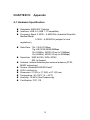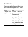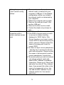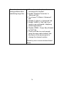
1
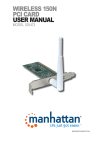
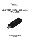
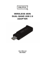
WIRELESS 450N DUAL BAND USB 2.0 ADAPTER User Manual DN-70650 COPYRIGHT Copyright ©2005/2006 by DIGITUS®. All rights reserved. No part of this publication may be reproduced, transmitted, transcribed, stored in a retrieval system, or translated into any language or computer language, in any form or by any means, electronic, mechanical, magnetic, optical, chemical, manual or otherwise, without the prior written permission of this company DIGITUS® makes no representations or warranties, either expressed or implied, with respect to the contents hereof and specifically disclaims any warranties, merchantability or fitness for any particular purpose. Any software described in this manual is sold or licensed "as is". Should the programs prove defective following their purchase, the buyer (and not this company, its distributor, or its dealer) assumes the entire cost of all necessary servicing, repair, and any incidental or consequential damages resulting from any defect in the software. Further, DIGITUS® reserves the right to revise this publication and to make changes from time to time in the contents thereof without obligation to notify any person of such revision or changes. 2 TABLE OF CONTENTS CHAPTER I: Product Information ........................................................ 5 1-1 Introduction and safety information ..................................................... 5 1-2 Safety Information .............................................................................. 6 1-3 System Requirements ........................................................................ 7 1-4 Package Contents .............................................................................. 8 1-5 Know your new wireless network card ................................................ 9 CHAPTER II: Driver Installation and Configuration ....................... 10 2-1 Network Card Installation.................................................................. 10 2-2 Connect to Wireless Access Point .................................................... 20 2-2-1 Using Ralink Utility ................................................................. 20 2-2-2 Using Windows Zero Configuration (Windows XP Only) ........ 25 2-3 Connection Profile Management ...................................................... 29 2-3-1 Add a new entry ..................................................................... 29 2-3-2 Remove an existing profile ..................................................... 33 2-3-3 Edit an existing profile ............................................................ 34 2-3-4 Import / Export profile ............................................................. 35 2-3-5 WPS Profile Setup.................................................................. 38 2-3-5-1 PBC mode WPS configuration ..................................... 40 2-3-5-2 PIN mode WPS configuration ...................................... 41 2-4 View Link Status ............................................................................... 43 2-5 Advanced Settings ............................................................................ 46 2-5-1 ‘Advanced’ menu .................................................................... 46 2-5-2 Wi-Fi Direct ............................................................................ 47 2-5-2-1 Establish connection with P2P device .......................... 51 2-5-2-2 Accept Wi-Fi Direct Connection Request ..................... 53 2-5-2-3 Wi-Fi Direct / Legacy client concurrent mode............... 54 2-5-2-4 Autonomous GO .......................................................... 55 2-5-2-5 Media sharing .............................................................. 57 CHAPTER III: Soft-AP Function.......................................................... 61 3-1 Switch to AP Mode and Station Mode ............................................... 61 3-2 Configure AP .................................................................................... 63 3-3 Advanced Functionality ..................................................................... 68 3-4 Access Control .................................................................................. 69 3-5 Associate List.................................................................................... 71 3-6 About ................................................................................................ 72 3 CHAPTER IV: Appendix.................................................................... 73 4-1 Hardware Specification ..................................................................... 73 4-2 Troubleshooting ................................................................................ 74 4-3 Glossary ........................................................................................... 77 4-4 FCC and Other Compliance Statements........................................... 81 4 Chapter I: Product Information 1-1 Introduction and safety information Thank you for purchasing this extreme high-speed 802.11a/b/g/n dual band wireless network card! Excepting common wireless standards 802.11a/b/g, this wireless network card is also 802.11n compatible - data transfer rate is 450Mbps, and that’s night times faster than 802.11g wireless network! 802.11n also provides wider wireless coverage, so you don’t have to worry if your computer is far from your wireless access point. With easy-to-install USB 2.0 interface - a very common expansion port of computers - plug this wireless network card into any empty USB port of your computer, just that simple! Other features of this product including: Portable dongle type design. Supports Infrastructure, Ad-Hoc, and Wi-Fi Direct connection method. QoS function: provides Wi-Fi Multimedia (WMM) quality of service to secure audio/video/voice data traffic as higher priority. 802.11a/b/g/n compatible. Supports major encryption methods like WEP, WPA, and WPA2 encryption. WPS configuration - You don’t need an experienced computer technician to help you to get connected. With WPS, you can get your computer connected by simply pushing a button on USB network card or entering an 8-digit code. USB 2.0 interface - you can get it installed on your computer in just few seconds! Wireless access control - prevent unauthorized network access to your network and computer. 5 1-2 Safety Information In order to keep the safety of users and your properties, please follow the following safety instructions: 1. This USB wireless network card is designed for indoor use only. DO NOT expose this network card to direct sun light, rain, or snow. 2. DO NOT put this network card at or near hot or humid places, like kitchen or bathroom. Also, do not left this wireless network card in the car in summer. 3. This network card is small enough to put in a child’s mouth, and it could cause serious injury or could be fatal. If they throw the network card, the card will be damaged. PLEASE KEEP THIS NETWORK CARD OUT THE REACH OF CHILDREN! 4. This network card will become hot when being used for long time (This is normal and is not a malfunction). DO NOT put the network card on a paper, cloth, or other flammable objects after the network card has been used for a long time. 5. There’s no user-serviceable part inside the network card. If you found that the network card is not working properly, please contact your dealer of purchase and ask for help. DO NOT disassemble the network card by yourself, warranty will be void. 6. If the network card falls into water, DO NOT USE IT AGAIN BEFORE YOU SEND THE CARD TO THE DEALER OF PURCHASE FOR INSPECTION. 7. If you smell something strange or even see some smoke coming out from the network card, switch the computer off immediately, and call dealer of purchase for help. 6 1-3 System Requirements An empty USB 2.0 port (May not be able work with USB 1.1 port, and performance will be greatly reduced) Windows XP, Vista, or Windows 7 operating system CD-ROM drive At least 100MB of available disk space 7 1-4 Package Contents Before you starting to use this wireless network card, please check if there’s anything missing in the package, and contact your dealer of purchase to claim for missing items: USB Wireless Network Card (1 pcs) Quick installation guide (1 pcs) Driver/Utility/User Manual CD-ROM (1 pcs) 3 2 8 1 2 3 1 1-5 Know your new wireless network card 1. 2. 3. 4. USB Connector External Wireless Antenna Link/Activity LED WPS Button (Press to activate WPS pairing mode) 2 3 1 4 LED Name Light Status Link/ Blinking Activity Off Description Linked to a wireless access point / Transferring data Power off 9 CHAPTER II: Driver Installation and Configuration 2-1 Network Card Installation Please follow the following instructions to install your new wireless network card: 1. Insert the USB wireless network card into an empty USB 2.0 port of your computer when computer is switched on. Never use force to insert the card, if you feel it’s stuck, flip the card over and try again. 2. Insert device driver CDROM into the CD/DVD ROM drive of your computer, and execute ‘Setup.exe’ program in ‘Driver’ folder. 10 3. On Windows Vista / Windows 7 computer, you may see UAC (User Account Control) window popup to warn you that this program is going to make changes to your computer, click ‘Yes’ to continue. 11 4. Please select ‘I accept the terms of the license agreement’, then click ‘Next’. 12 5. Select ‘Install driver and Ralink WLAN Utility’ and click ‘Next’ to continue. Optionally, you can select ‘Install driver only’ to install wireless network card driver only, and use Windows’ built-in wireless manager. If you don’t know which one you should choose, select ‘Install driver and Ralink WLAN Utility’ for maximum functionality. 13 (Windows XP Only) 14 6. Select the wireless configuration utility you wish to use, than click ‘Next’ to continue. It’s recommended to select ‘Ralink Configuration Tool’ for maximum functionality. If you used to use Windows’ built-in configuration tool, select ‘Microsoft Zero Configuration Tool’. (Windows XP Only) 15 7. Click ‘Install’ to continue. Please note: If you see this message, click ‘Install this driver software anyway’ to continue. 16 8. Please be patient while installation is in progress, this may require few minutes. 17 9. Click ‘Finish’ to finish installation procedure. 10. Please insert your USB wifi network card to any empty USB port now. A popup message indicating that your computer found ‘802.11n USB Wireless LAN Card’ will appear. Please be patient while Windows is installation driver. This message will only appear when you insert the USB wifi network card to your computer’s USB port, or you insert the network card to a different USB port of your computer. 18 11. You should be able to see this popup message, indicating your new USB network is ready to use; If not, please either try to re-install driver, or insert the network card to another USB port of your computer. (Windows XP) (Windows Vista / 7) 12. A new icon will appear near the clock of system tray: HERE! Left-click the icon will launch wireless network configuration utility, and you can right-click the icon to show the quick menu of configuration utility. This icon uses 5 colors to represent current network status: (Green) (Yellow) (Red) (Blue) (Black) Network connection established, signal strength good Network connection established, signal strength normal Network connection established, signal strength poor Network connection is not yet established Network card not found on your computer For detailed instructions of wireless network configuration utility, please refer to next chapter. 19 2-2 Connect to Wireless Access Point To use wireless network, you have to connect to a wireless access point first. You can either use Ralink utility (comes with network card driver), or Windows Zero Config utility (comes with Windows operating system) 2-2-1 Using Ralink Utility Please follow the following instructions to use Ralink configuration utility to connect to wireless access point. 1. Left-click the Ralink configuration utility icon located at lower-right corner of computer desktop, and configuration menu will appear: HERE! 2. Wireless utility will appear. Click ‘Site Survey’ button to open the list of available wireless networks (and their status). 20 There are 6 fields in ‘Site Survey’ list: Field# 1 (SSID) 2 (Type) 3 (Channel) 4 (Wireless mode) Description The Service-Set IDentifier of network device (The name of network device) The type of network device Infrastructure (Access Point) Ad-Hoc The channel number of this network device Available wireless mode. 802.11a wireless capability 802.11b wireless capability 802.11g wireless capability 802.11n wireless capability 21 5 (Security) Security mode. When nothing is displayed here, means this network device does not require security and anyone can connect to it. 6 (Signal Strength) Shows the wireless signal strength in percentage. Higher percentage means better signal quality. 3. To connect to a wireless access point, double click on it: 4. If the wireless access point you wish to connect does not appear button to scan for wireless here, you can click ‘Refresh’ access points again; if the wireless access point you’re looking for still not appear, try to move the computer closer. 5. You’ll be prompted with wireless access point’s encryption method (if any): Click right arrow to continue. Generally you don’t have to change encryption method, it will be detected automatically. If you selected a wrong encryption method, connection will not be able to establish. 22 6. Please input encryption key (or passphrase, depends on encryption method) here, then click right arrow. 23 7. Network card will attempt to connect to access point now, this may require few seconds to minutes, please be patient. When you see there’s a check shown beside the access point you wish to connect, your computer is connected to access point you selected. The connection status will be displayed in configuration utility also. (see example picture below). Windows will prompt you for establish connection also: 24 2-2-2 Using Windows Zero Configuration (Windows XP Only) Windows XP and Vista has a built-in wireless network configuration utility, called as ‘Windows Zero Configuration’ (WZC). You can also use WZC to configure your wireless network parameter: 1. Right-click configuration utility’s icon, and select ‘Use Zero Configuration as Configuration Utility’. In this mode, you can still use Ralink configuration utility to check the connection status, but unable to connect to a wireless network, or change network setting. Follow the following steps to use WZC to establish network connection. If you wish to return to use Ralink configuration utility again, right-click Ralink configuration utility icon again, and select ‘Use RaConfig as Configuration Utility’. 25 2. Click ‘Start’ button (should be located at the bottom-left corner of windows desktop), click ‘Control Panel’, then click ‘Network and Internet Connections’ in Control Panel. 3. Click ‘Connect to a network’ under ‘Network Connections’ 26 4. Right-click ‘Wireless Network Connection’ (it may have a number as suffix if you have more than one wireless network card, please make sure you right-click the ‘802.11n Wireless LAN Card), then select ‘View Available Wireless Networks’. 5. All wireless access points in proximity will be displayed here. If the access point you want to use is not displayed here, please try to move your computer closer to the access point, or you can click ‘Refresh network list’ to rescan access points. Click the access point you want to use if it’s shown, then click ‘Connect’. 27 6. If the access point is protected by encryption, you have to input its security key or passphrase here. It must match the encryption setting on the access point. If the access point you selected does not use encryption, you’ll not be prompted for security key or passphrase. 7. If you can see ‘Connected’ message, the connection between your computer and wireless access point is successfully established. 28 2-3 Connection Profile Management For connections you’ll frequently use, you can save them as a profile and you can recall all settings (security type, password, etc.) back soon. 2-3-1 Add a new entry By this function you can setup the connection parameters for a specific wireless access point in advance, so you can recall a set of connection parameters quickly. To do this, follow the following procedures: 1. Click ‘Profile’ in configuration utility: 29 2. Profile manager will appear. Click plus sign profile. to add a new 3. Please name the profile in ‘Profile Name’ field, and select the AP you wish to connect in ‘SSID’ dropdown list, then click right arrow . If you’re connecting to a network device using AD-HOC connection method, select ‘Ad Hoc - Connect to other computers’ first. 30 4. Select this AP’s authentication and encryption method from dropdown list, then click right arrow . 5. Input passphrase key here (or WEP key, if required), then click right arrow : 6. Check this box if you wish to enable pre-logon connection. When this feature is enabled, wireless network connection will be established before you logon Windows so you can authenticate yourself against network server. If you don’t need to this, you can leave this box unchecked. Click right arrow continue. 31 7. The profile will be saved in the list: You can repeat step 2 to 6 to setup more profiles of wireless connection. When you wish to connect to a certain wireless access point, click ‘Active’ button (as indicated above). A check mark will be displayed beside active profile. 32 2-3-2 Remove an existing profile When you no longer need an existing profile, just select it from the button. list and click ‘Delete’ If the profile you wish to delete is active now, you’ll be prompted to confirm deletion: To delete anyway, click ‘OK’; to cancel, click 33 mark. 2-3-3 Edit an existing profile If you have added a profile before, and you wish to change the content of the profile, you can use this function. Please select a button. profile from the list first, then click ‘Edit’ You’ll be provided with the contents of selected profile; you can edit them and save changes. 34 2-3-4 Import / Export profile If you need to move your wireless settings to another computer, or you just want to make a backup, you can use import / export function to make a copy, or restore current profile. To backup a profile, click ‘Export’ 35 : You’ll be prompted to select a place to save profile setting file. Select a folder in your computer and name the profile, then click ‘Save’. To recall previously-saved profiles, click ‘Import’ 36 : Select a profile (file with .prof extension), and click ‘Open’ Please note that this will overwrite any existing profile(s). 37 2-3-5 WPS Profile Setup WPS (Wi-Fi Protected Setup) is a new, convenient way to setup secured wireless connections. You only need to push a button or input a set of 8-digit random number, and you can setup a secure connection between wireless devices, like what a professional wireless expert can do. To use WPS profile, you have to make sure the access point you wish to connect supports WPS first. You can discover if an access point is WPS-capable or not by site-survey: In this list, there are ten access points support WPS, which are icon. indicated by You can still establish secured connection with WPS-capable access points in conventional way. To establish WPS-style button: connection, click ‘Add WPS profile’ 38 You’ll be prompted to select WPS method and WPS AP: To use PIN (8-digit or 4-digit random number) to setup WPS, select ‘PIN / numeric code’, and you have to select an AP from ‘WPS AP List’ dropdown menu; to establish connection by Push-Button Configuration (PBC), you don’t have to select an AP from ‘WPS AP List’ dropdown list. Note: This device follows WPS 2.0 Standard Specification to allow inputting 4-digit PIN code, pls. make sure your Wireless Router or Access Point supports WPS 2.0 accordingly, or use 8-digit PIN as usual. You can also check ‘Auto’ box and configuration utility will select a correct WPS-capable AP to connect when in PIN / numeric code mode. Click right arrow to continue. 39 2-3-5-1 PBC mode WPS configuration When you want to use ‘PBC’ mode: Click ‘Start PBC’ button: Now, please push the WPS button on the access point (a physical button or a software button in its configuration menu - please refer to access point’s user manual) within 2 minutes. 40 2-3-5-2 PIN mode WPS configuration There are two roles in PIN mode WPS configuration: registrar and enrollee. Registrar is the one who waits for incoming WPS request, and enrollee is the one who searches for WPS registrar and will attempt to connect it. The WPS role of two devices should not be same: When one device is registrar, the other one must be enrollee, and vice versa. To setup WPS connection by PIN, select ‘PIN / numeric code’, then arrow. click right There will be a menu displaying 8-digit WPS PIN code on the configuration menu, please get this number. Please remember the number will become invalid after a short period of time (2 minutes or so). 41 Select ‘Enrollee’ in ‘Config mode’ dropdown list, and input PIN code arrow. in ‘Pin Code’, then click right Click ‘StartPIN’ to begin WPS connection, please be patient. You’ll be prompted when WPS connection is established successfully; if you received an error, you can try again, but please remember to make sure the PIN you obtained from access point is still valid. 42 2-4 View Link Status You can check the status of active wireless connection by clicking button: ‘Link Information’ A new window will appear: 43 There are 3 kinds of link information: a. Link status Displays the status of active connection. b. Throughput Displays the throughput of active connection. 44 c. Statistics Displays the statistics of active connection. Select ‘Transmit’ or ‘Receive’ to switch displaying statistics of transmitted and received data packets. To reset counters, click 45 2-5 Advanced Settings button to show advanced configuration menu. Click ‘Advanced’ In this menu, you can configure some advanced wireless settings. Normally you don’t need to change these settings to establish wireless connection. Only change these settings when you know what you’re doing and you really need these changes. 2-5-1 ‘Advanced’ menu You can configure wireless frequency and available radio channels here. 46 2-5-2 Wi-Fi Direct Wi-Fi direct is a new technology. You can establish direct connections with one or more network devices which also support this technology without the help of wireless access point. It’s similar to Ad-Hoc mode but more simple and powerful. To enable Wi-Fi direct, double-click the computer icon: You’ll be prompted to input the name of your computer. It will use your computer’s name by default, however, you can input a new one here by selecting the blank field below and input a new name, to continue. then click right arrow 47 Your computer will enter Wi-Fi direct standby mode and scan for any Wi-Fi direct capable computer nearby. When one or more device(s) is found, you’ll see the topology of all nearby devices, like the example shown below: 48 In this topology: GO (Group Owner) indicates an AP-like device. This indicates this device is the head of one or more client devices (multiple clients belong to this GO). indicates you can configure secured connection with this device by WPS indicates this device uses WPA2AES key. 49 To access more Wi-Fi direct functionalities, right-click on the laptop icon on the bottom-left corner, and a menu will appear: Click ‘Scan’ to discover nearby Wi-Fi Direct devices. (see example below, 2 nearby devices are found) For descriptions of other functionalities, see chapters below. 50 2-5-2-1 Establish connection with P2P device To establish connection with a P2P (peer to peer) device, double-click on its icon, and you’ll be prompted to select its WPS connection type: (an example as below) Double click on icon 51 Please select a WPS type here. Push-Button Configuration: Using PBC configuration method to establish connection. Display PIN: Using display PIN method to establish connection. When in this method, you’ll see a 8-digit number shown here. Input this number on another device to establish connection. Enter PIN: Input the 8-digit PIN number displayed on another device in ‘PIN Code’ field to establish connection. Then click right arrow to continue. 52 2-5-2-2 Accept Wi-Fi Direct Connection Request When your computer’s Wi-Fi direct function is enabled, and some other computer wishes to connect with your computer, you’ll be prompted by a pop-up message: Click the pop-up message to accept incoming connection request. Then, When Wi-Fi Direct is successfully connected, you will see a straight line between 2 devices. (See example as below) 53 2-5-2-3 Wi-Fi Direct / Legacy client concurrent mode This wireless network card can operate in both Wi-Fi direct and legacy wireless network client mode. So you can establish Wi-Fi direct connection and connect to access point at the same time. When Wi-Fi direct is enabled, you can right-click Ralink utility icon, and a menu will appear: There are 2 modes available: Switch to Client + AP Mode: enable network client and access point functionality at the same time. Switch to AP Mode: Enable access point mode only. 54 2-5-2-4 Autonomous GO Enable this function to allow other users to initiate a Wi-Fi Direct ‘GO’ directly. To use this function, select ‘Enable autonomous GO’ by right-clicking laptop icon at the bottom-left corner: You’ll be prompted to input a WPA2-PSK key for autonomous GO: 55 You’ll also be prompted to select an operating channel for this autonomous GO connection: Select a preferred channel in ‘Preferred channel’ dropdown list, button to finish. then click 56 2-5-2-5 Media sharing You can share files on your computer with other Wi-Fi direct points. To enable this function, right-click on the laptop icon on the bottom-left corner, and a menu will appear: Click ‘Media Sharing’ to continue. You’ll be prompted to select a folder on your computer for file sharing. 57 to select a folder, then click right You can click folder icon arrow to start sharing files on your computer. For security reasons, do not select a folder which contains sensitive or personal files, only select the folder which contains public files. Please note that a new folder named ‘Media Sharing’ will be created under ‘C:\Users\XXX\Documents’ folder, where ‘XXX’ is your user name in Windows. Other users may access the files on your computer now. To stop sharing file, click stop button. 58 After you enabled media sharing function, other computers can see your sharing folder by clicking ‘Network’ item in Windows Explorer: Double-click ‘Ralink Media Server’ icon to open Windows media player, users can select the category of media files you shared. 59 60 CHAPTER III: Soft-AP Function Excepting become a wireless client of other wireless access points, this wireless card can act as a wireless service provider also! You can switch this wireless card’s operating mode to ‘AP’ mode to simulate the function of a real wireless access point by software, and all other computers and wireless devices can connect to your computer wirelessly, even share the internet connection you have! Please follow the instructions in following chapters to use the AP function of your wireless card. 3-1 Switch to AP Mode and Station Mode The operating mode of the wireless card is ‘Station Mode’ (becoming a client of other wireless access points) by default. If you want to switch to AP mode, please right-click configuration utility icon, and click ‘Switch to AP Mode’. (Windows XP Only) You’ll see the configuration utility’s icon switched to ‘AP’ icon. Notice: If you receive windows firewall (or other firewalling software) warns you about access point utility, please click ‘Unblock’ (or similar), or software AP will not function normally. 61 To launch AP manager, right-click configuration utility’s icon, and select ‘Launch Config Utilities’. The soft-AP configuration utility will appear, along with the status of software AP: 62 3-2 Configure AP To use software AP, you need to configure it first to accept incoming button to continue. wireless connections. Click ‘Config AP’ You have to input the SSID of this software AP first: Input SSID in ‘SSID’ field. If you wish to hide SSID so only clients who know your actual SSID can get connected, check ‘Hide SSID’ box. 63 You can also change wireless operating mode by ‘Wireless Mode’ . dropdown menu. When you finish, click right arrow In this page, you can select the country region of this software AP. Different country has different radio regulation and therefore it would be illegal to use certain channel (frequency) in some countries. Please select a correct country region to avoid legal problem. Note: You may not be able to change this option in some countries due to legal requirements. You can also select wireless channel of this software AP by ‘Channel’ dropdown list. If you wish to enable 40MHz Bandwidth capability, check ‘Enable 40 MHz Bandwidth’ box. When you finish, click right arrow 64 . In this page, you have to select the authentication and encryption method of this software AP. Available ‘Authentication’ options are: Open: No security. Anyone who found this AP can get connected. Shared: Use shared key authentication (WEP). WPA-PSK: Use WPA-PSK authentication. WPA2-PSK: Use WPA2-PSK authentication. WPA-PSK / WPA2-PSK: Allows both WPA-PSK and WPA2-PSK authentication. Available ‘Encryption’ options are (This menu will vary when you select different authentication method): Not Encryption: No security WEP: Use WEP (Wired Equivalent Privacy) encryption. TKIP: Use TKIP encryption. AES: Use AES encryption. When you finish, click right arrow . In this page, you can configure WEP / WPA passphrase (password). 65 For WEP: Select default Tx Key (normally you can just use Key 1), Key Format (Hex characters or ASCII characters), and input WEP key. If you select Hex key format, input 10 or 26 characters (number 0-9 and alphabets A-F); if you select ASCII, input 5 or 13 characters (number 0-9 and alphabets). 66 For WPA-PSA / WPA2-PSK: Input WPA-PSK / WPA2-PSK key here. If you wish to change group rekey time interval, you can change it, but normally you don’t need to change it and software AP will still work fine. WPA-PSK / WPA2-PSK key must be 8 to 63 ASCII characters or 64 Hex characters. When you finish, click right arrow . After you finish this step, your software AP is ready and able to accept incoming connection requests. 67 3-3 Advanced Functionality To setup advanced software AP functionality, click ‘Advanced’ button. There are several setup items: No forwarding among wireless clients: Check this box and every wireless clients will not be able to communicate with each other. Beacon Interval (ms): Change wireless radio beacon time interval in milliseconds. Normally you don’t have to change this setting. TX Power: Change the wireless radio output power here. Please select a proper output power and you can avoid some unwanted wireless intruders. Idle time: The allowed time before proceeding with the authentication. Normally you don’t have to change this setting. Click ‘Apply’ button to save changes. 68 3-4 Access Control You can allow or disallow certain wireless clients to connect your software AP by this function. To setup access control, click ‘Access Control List’ button . Access control list will appear: First you have to select access control policy: Disable: No access controlling 69 Allow All: Only allow clients in the list to establish connection (white list). Reject All: Rejects all clients in the list to establish connection (black list). Then you have to input the 12-character MAC address in ‘MAC Address’ field. You may find the MAC address of a certain network card on itself (something like a label). Please note that you don’t have to input : (colon) or - (dash) character between every 2 MAC address characters. Click ‘Add’ to add this MAC address in the list. To delete a MAC address in the list, select it and click ‘Delete’ button; to delete all entries, click ‘Remove All’ button. Click ‘Apply’ button to save changes. 70 3-5 Associate List You can see the list of all wireless clients that connected to this software AP. Click ‘Connected Devices’ button to show the list. 71 3-6 About Click this button to see the version information of software AP configuration utility. 72 CHAPTER IV: Appendix 4-1 Hardware Specification Standards: IEEE 802.11a/b/g/n Interface: USB 2.0 (USB 1.1 Compatible) Frequency Band: 2.4000 ~ 2.4835GHz (Industrial Scientific Medical Band) 5.1500 ~ 5.8250GHz (subject to local regulations) Data Rate: 11b: 1/2/5.5/11Mbps 11g: 6/9/12/24/36/48/54Mbps 11n (20MHz): MCS0-23 (up to 216Mbps) 11n (40MHz): MCS0-23 (up to 450Mbps) Securities: WEP 64/128, WPA, WPA2 802.1x Support Antenna: Internal Antenna plus external antenna (3T3R, MIMO technology) Drivers: Windows 2000/XP/Vista/7 LED: Link/Activity Dimension: 27.2(H) x 17.2(W) x 87.1(D) mm Temperature: 32~104°F (0 ~ 40°C) Humidity: 10-95% (NonCondensing) Certification: FCC, CE 73 4-2 Troubleshooting If you encounter any problem when you’re using this wireless network card, don’t panic! Before you call your dealer of purchase for help, please check this troubleshooting table, the solution of your problem could be very simple, and you can solve the problem by yourself! Scenario Solution I can’t find any wireless 1. Click ‘Rescan’ for few more times access point / wireless and see if you can find any wireless device in ‘Site Survey’ access point or wireless device. function. 2. Please move closer to any known wireless access point. 3. ‘Ad hoc’ function must be enabled for the wireless device you wish to establish a direct wireless link. 4. Please adjust the position of network card (you may have to move your computer if you’re using a notebook computer) and click ‘Rescan’ button for few more times. If you can find the wireless access point or wireless device you want to connect by doing this, try to move closer to the place where the wireless access point or wireless device is located. 74 Nothing happens when I click ‘Launch config utilities’ I can not establish connection with a certain wireless access point 1. Please make sure the wireless network card is inserted into your computer’s USB port. If the Realtek configuration utility’s icon is black, the network card is not detected by your computer. 2. Reboot the computer and try again. 3. Remove the card and insert it into another USB port. 4. Remove the driver and re-install. 5. Contact the dealer of purchase for help. 1. Click ‘Connect’ for few more times. 2. If the SSID of access point you wish to connect is hidden (nothing displayed in ‘SSID’ field in ‘Site Survey’ function), you have to input correct SSID of the access point you wish to connect. Please contact the owner of access point to ask for correct SSID. 3. You have to input correct passphrase / security key to connect an access point with encryption. Please contact the owner of access point to ask for correct passphrase / security key. 4. The access point you wish to connect only allows network cards with specific MAC address to establish connection. Please go to ‘About’ tab and write the value of ‘Phy_Addess’ down, then present this value to the owner of access point so he / she can add the MAC address of your network card to his / her access point’s list. 75 The network is slow / having problem when transferring large files 1. Move closer to the place where access point is located. 2. Enable ‘Wireless Protection’ in ‘Advanced’ tab. 3. Try a lower TX Rate in ‘Advanced’ tab. 4. Disable ‘Tx Burst’ in ‘Advanced’ tab. 5. Enable ‘WMM’ in ‘QoS’ tab if you need to use multimedia / telephony related applications. 6. Disable ‘WMM – Power Save Enable’ in ‘QoS’ tab. 7. There could be too much people using the same radio channel. Ask the owner of the access point to change the channel number. Please try one or more solutions listed above. 76 4-3 Glossary 1. What is the IEEE 802.11g standard? 802.11g is the new IEEE standard for high-speed wireless LAN communications that provides for up to 54 Mbps data rate in the 2.4 GHz band. 802.11g is quickly becoming the next mainstream wireless LAN technology for the home, office and public networks. 802.11g defines the use of the same OFDM modulation technique specified in IEEE 802.11a for the 5 GHz frequency band and applies it in the same 2.4 GHz frequency band as IEEE 802.11b. The 802.11g standard requires backward compatibility with 802.11b. The standard specifically calls for: A. A new physical layer for the 802.11 Medium Access Control (MAC) in the 2.4 GHz frequency band, known as the extended rate PHY (ERP). The ERP adds OFDM as a mandatory new coding scheme for 6, 12 and 24 Mbps (mandatory speeds), and 18, 36, 48 and 54 Mbps (optional speeds). The ERP includes the modulation schemes found in 802.11b including CCK for 11 and 5.5 Mbps and Barker code modulation for 2 and 1 Mbps. B. A protection mechanism called RTS/CTS that governs how 802.11g devices and 802.11b devices interoperate. 2. What is the IEEE 802.11b standard? The IEEE 802.11b Wireless LAN standard subcommittee, which formulates the standard for the industry. The objective is to enable wireless LAN hardware from different manufactures to communicate. 77 3. What does IEEE 802.11 feature support? The product supports the following IEEE 802.11 functions: CSMA/CA plus Acknowledge Protocol Multi-Channel Roaming Automatic Rate Selection RTS/CTS Feature Fragmentation Power Management 4. What is Ad-hoc? An Ad-hoc integrated wireless LAN is a group of computers, each has a Wireless LAN card, Connected as an independent wireless LAN. Ad hoc wireless LAN is applicable at a departmental scale for a branch or SOHO operation. 5. What is Infrastructure? An integrated wireless and wireless and wired LAN is called an Infrastructure configuration. Infrastructure is applicable to enterprise scale for wireless access to central database, or wireless application for mobile workers. 6. What is BSS ID? A specific Ad hoc LAN is called a Basic Service Set (BSS). Computers in a BSS must be configured with the same BSS ID. 7. What is WEP? WEP is Wired Equivalent Privacy, a data privacy mechanism based on a 40 bit shared key algorithm, as described in the IEEE 802 .11 standard. 8. What is TKIP? TKIP is a quick-fix method to quickly overcome the inherent weaknesses in WEP security, especially the reuse of encryption keys. TKIP is involved in the IEEE 802.11i WLAN security standard, and the specification might be officially released by early 2003. 78 9. What is AES? AES (Advanced Encryption Standard), a chip-based security, has been developed to ensure the highest degree of security and authenticity for digital information, wherever and however communicated or stored, while making more efficient use of hardware and/or software than previous encryption standards. It is also included in IEEE 802.11i standard. Compare with AES, TKIP is a temporary protocol for replacing WEP security until manufacturers implement AES at the hardware level. 10. Can Wireless products support printer sharing? Wireless products perform the same function as LAN products. Therefore, Wireless products can work with Netware, Windows 2000, or other LAN operating systems to support printer or file sharing. 11. Would the information be intercepted while transmitting on air? WLAN features two-fold protection in security. On the hardware side, as with Direct Sequence Spread Spectrum technology, it has the inherent security feature of scrambling. On the software side, WLAN series offer the encryption function (WEP) to enhance security and Access Control. Users can set it up depending upon their needs. 12. What is DSSS? What is FHSS? And what are their differences? Frequency-hopping spread-spectrum (FHSS) uses a narrowband carrier that changes frequency in a pattern that is known to both transmitter and receiver. Properly synchronized, the net effect is to maintain a single logical channel. To an unintended receiver, FHSS appears to be short-duration impulse noise. Direct-sequence spread-spectrum (DSSS) generates a redundant bit pattern for each bit to be transmitted. This bit pattern is called a chip (or chipping code). The longer the chip is, the greater the probability that the original data can be recovered. Even if one or more bits in the chip are 79 damaged during transmission, statistical techniques embedded in the radio can recover the original data without-the need for retransmission. To an unintended receiver, DSSS appears as low power wideband noise and is rejected (ignored) by most narrowband receivers. 13. What is Spread Spectrum? Spread Spectrum technology is a wideband radio frequency technique developed by the military for use in reliable, secure, mission-critical communication systems. It is designed to trade off bandwidth efficiency for reliability, integrity, and security. In other words, more bandwidth is consumed than in the case of narrowband transmission, but the trade off produces a signal that is, in effect, louder and thus easier to detect, provided that the receiver knows the parameters of the spread-spectrum signal being broadcast. If a receiver is not tuned to the right frequency, a spread –spectrum signal looks like background noise. There are two main alternatives, Direct Sequence Spread Spectrum (DSSS) and Frequency Hopping Spread Spectrum (FHSS). 14. What is WPS? WPS stands for Wi-Fi Protected Setup. It provides a simple way to establish unencrypted or encrypted connections between wireless clients and access point automatically. User can press a software or hardware button to activate WPS function, and WPS-compatible wireless clients and access point will establish connection by themselves. There are two types of WPS: PBC (Push-Button Configuration) and PIN code. 80 4-4 FCC and Other Compliance Statements Federal Communication Commission Interference Statement This equipment has been tested and found to comply with the limits for a Class B digital device, pursuant to Part 15 of FCC Rules. These limits are designed to provide reasonable protection against harmful interference in a residential installation. This equipment generates, uses, and can radiate radio frequency energy and, if not installed and used in accordance with the instructions, may cause harmful interference to radio communications. However, there is no guarantee that interference will not occur in a particular installation. If this equipment does cause harmful interference to radio or television reception, which can be determined by turning the equipment off and on, the user is encouraged to try to correct the interference by one or more of the following measures: 1. Reorient or relocate the receiving antenna. 2. Increase the separation between the equipment and receiver. 3. Connect the equipment into an outlet on a circuit different from that to which the receiver is connected. 4. Consult the dealer or an experienced radio technician for help. FCC Caution This device and its antenna must not be co-located or operating in conjunction with any other antenna or transmitter. This device complies with Part 15 of the FCC Rules. Operation is subject to the following two conditions: (1) this device may not cause harmful interference, and (2) this device must accept any interference received, including interference that may cause undesired operation. Any changes or modifications not expressly approved by the party responsible for compliance could void the authority to operate equipment. 81 Federal Communication Commission (FCC) Radiation Exposure Statement This equipment complies with FCC radiation exposure set forth for an uncontrolled environment. In order to avoid the possibility of exceeding the FCC radio frequency exposure limits, human proximity to the antenna shall not be less than 20cm (8 inches) during normal operation. The antenna(s) used for this transmitter must not be co-located or operating in conjunction with any other antenna or transmitter. R&TTE Compliance Statement This equipment complies with all the requirements of DIRECTIVE 1999/5/EC OF THE EUROPEAN PARLIAMENT AND THE COUNCIL of March 9, 1999 on radio equipment and telecommunication terminal Equipment and the mutual recognition of their conformity (R&TTE) The R&TTE Directive repeals and replaces in the directive 98/13/EEC (Telecommunications Terminal Equipment and Satellite Earth Station Equipment) As of April 8, 2000. Safety This equipment is designed with the utmost care for the safety of those who install and use it. However, special attention must be paid to the dangers of electric shock and static electricity when working with electrical equipment. All guidelines of this and of the computer manufacture must therefore be allowed at all times to ensure the safe use of the equipment. EU Countries Intended for Use The ETSI version of this device is intended for home and office use in Austria, Belgium, Denmark, Finland, France, Germany, Greece, Ireland, Italy, Luxembourg, the Netherlands, Portugal, Spain, Sweden, and the United Kingdom. The ETSI version of this device is also authorized for use in EFTA member states: Iceland, Liechtenstein, Norway, and Switzerland. EU Countries Not intended for use None. 82