1
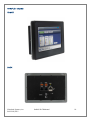
SeaPAC R9-7R ARM9 Touchscreen Computer
User Manual
Item#
©Sealevel Systems, Inc.
SL9259 6/2015
SeaPAC R9-7R Manual
S96100-7R
1
Contents
Introduction .............................................................................................................................................................. 4
Features ..................................................................................................................................................................... 4
Regulatory ................................................................................................................................................................. 5
FCC Statement ....................................................................................................................................................... 5
European Community ........................................................................................................................................... 5
Before You Get Started ............................................................................................................................................. 6
What’s Included ..................................................................................................................................................... 6
Advisory Conventions ........................................................................................................................................... 6
Important Safety Instructions ............................................................................................................................... 7
Optional Items ....................................................................................................................................................... 8
Cables .................................................................................................................................................................... 8
Product Overview ...................................................................................................................................................... 9
Specifications ........................................................................................................................................................ 9
Processor ............................................................................................................................................................... 9
Memory .................................................................................................................................................................. 9
Display ................................................................................................................................................................... 9
Touchscreen .......................................................................................................................................................... 9
Bus Interfaces ........................................................................................................................................................ 9
Industrial I/O ......................................................................................................................................................... 9
Audio ...................................................................................................................................................................... 9
Power ..................................................................................................................................................................... 9
Product Views ...................................................................................................................................................... 10
Front ..................................................................................................................................................................... 10
Back ...................................................................................................................................................................... 10
Technical Description ............................................................................................................................................. 11
Memory ................................................................................................................................................................ 11
Ethernet ............................................................................................................................................................... 11
USB ....................................................................................................................................................................... 11
Display and Touchscreen ................................................................................................................................... 12
Serial Communications ....................................................................................................................................... 12
Software .................................................................................................................................................................. 15
SeaPAC R9-7R Quick Start .................................................................................................................................. 15
Windows Device Center ...................................................................................................................................... 17
Windows ActiveSync for XP ................................................................................................................................. 18
Connection Complete ......................................................................................................................................... 19
©Sealevel Systems, Inc.
SL9259 6/2015
SeaPAC R9-7R Manual
2
Programming using the .NET Compact Framework ......................................................................................... 20
Application Development ................................................................................................................................... 20
Application Debugging ....................................................................................................................................... 25
Introduction ......................................................................................................................................................... 25
Requirements ...................................................................................................................................................... 25
Debugging an Application .................................................................................................................................. 25
Attach the Debugger........................................................................................................................................... 26
Breakpoints .......................................................................................................................................................... 28
Watching Variables .............................................................................................................................................. 30
Target Deployment and Execution .................................................................................................................... 31
Boot Sequence ..................................................................................................................................................... 32
OS File Restoration .............................................................................................................................................. 32
Upgrading the OS Runtime Image on NAND Flash ........................................................................................... 32
Network Configuration ....................................................................................................................................... 36
Specifications .......................................................................................................................................................... 40
Dimensions .......................................................................................................................................................... 40
Power ................................................................................................................................................................... 40
Power Adapter ..................................................................................................................................................... 40
Environmental Specifications ............................................................................................................................. 41
CERTIFICATIONS / Approvals ............................................................................................................................. 41
Product Marking .................................................................................................................................................. 41
Manufacturing ..................................................................................................................................................... 41
Appendix A – Resources ........................................................................................................................................ 42
Books ................................................................................................................................................................... 42
Websites ............................................................................................................................................................... 42
Appendix B – Application Debugging over Ethernet............................................................................................ 43
Appendix C – Installation ....................................................................................................................................... 45
Panel Cut Out ...................................................................................................................................................... 45
Installation Instructions ...................................................................................................................................... 45
Appendix D – CAD Drawing ................................................................................................................................... 47
Appendix E – How to Get Assistance .................................................................................................................... 48
Technical Support ............................................................................................................................................... 48
Warranty .................................................................................................................................................................. 49
Warranty Policy ....................................................................................................................................................... 49
Non-Warranty Repair/Retest ............................................................................................................................... 49
How to Obtain an RMA (Return Merchandise Authorization) .......................................................................... 49
©Sealevel Systems, Inc.
SL9259 6/2015
SeaPAC R9-7R Manual
3
Introduction
The SeaPAC R9-7R is an application-ready platform for your next product design. The system is based on
the 400MHz Atmel AT91SAM9G45 microcontroller boasting a 32-bit ARM® instruction set for maximum
performance.
To provide the fastest time to market, the Windows CE 6.0 BSP binary and low-level drivers for system I/O
are included. Additionally, the SeaPAC R9-7R software package is equipped with the Sealevel Talos I/O
Framework, which offers a high-level object-oriented .NET Compact Framework (CF) device interface. This
interface provides an I/O point abstraction layer with built-in support for the specific needs of analog and
digital I/O such as gain control and debouncing.
The SeaPAC R9-7R is housed in a rugged enclosure suitable for panel mounting and is rated for a –30°C to
+70°C operating temperature range. The SeaPAC R9-7R is powered from your 5VDC LPS source, or optional
power supply adapter.
Features
7” WVGA 300 nit TFT LCD with LED backlight
Durable resistive touchscreen
Atmel AT91SAM9G45 ARM® Processor
128MB DDR2 RAM
(1) 10/100 BaseT Ethernet
(1) USB 2.0 Port (high retention)
(1) USB Device Port (high retention for Debug)
(2) Isolated RS-485 serial ports
5 VDC @ 1.5 A power input via COM A (RJ45) Port or Molex 2-pin connector
Includes 110 VAC to 5 VDC @ 2.5 A wall mount power supply
Power 7.5W Max
Compatible with Windows Embedded CE 6.0 and Linux
Panel mount NEMA 4 / IP65 rated bezel
©Sealevel Systems, Inc.
SL9259 6/2015
SeaPAC R9-7R Manual
4
Regulatory
FCC STATEMENT
This equipment has been tested and found to comply with the limits for a Class A digital
device, pursuant to part 15 of the FCC Rules. Operation is subject to the following two
conditions: (1) This device may not cause harmful interference, and (2) this device must
accept any interference received, including interference that may cause undesired operation.
EUROPEAN COMMUNITY
This equipment has been evaluated or tested and found in compliance with the requirements
of the following directives issued by the European Commission:
•
Low Voltage Directive 2006/95/EC
•
EMC Directive 2004/108/EC
•
RoHS Directive 2011/65/EU
©Sealevel Systems, Inc.
SL9259 6/2015
SeaPAC R9-7R Manual
5
Before You Get Started
WHAT’S INCLUDED
The SeaPAC R9-7R is shipped with the following items. If any of these items are missing or damaged, please
contact Sealevel for replacement.
•
SeaPAC R9-7R ARM9 Touchscreen Computer with CE runtime image
•
TR146 110 VAC to 5 VDC @ 2.5 A wall mount power supply
•
CD with Talos .NET Framework, application samples, setup files, and documentation
•
Microsoft® Windows® CE 6.0 Core license
ADVISORY CONVENTIONS
Warning - The highest level of importance used to stress a condition where damage could result to
the product or the user could suffer serious injury.
Important– The middle level of importance used to highlight information that might not seem
obvious or a situation that could cause the product to fail.
Note – The lowest level of importance used to provide background information, additional tips, or
other non-critical facts that will not affect the use of the product.
©Sealevel Systems, Inc.
SL9259 6/2015
SeaPAC R9-7R Manual
6
IMPORTANT SAFETY INSTRUCTIONS
SAVE THIS MANUAL— It contains important safety and operating instructions for the installing and
configuring the SeaPAC R9-7R system.
Prior to beginning the installation, carefully read, understand, and follow all related safety
guidelines and documentation. This manual includes warnings, recommendations, and safety
precautions that must be observed.
•
Carefully follow all the installation instructions later in this manual.
•
There are no user-serviceable parts in the SeaPAC R9-7R system. Do not disassemble the
system. Contact the manufacturer if service or repair is required.
•
Only technically qualified service personnel are permitted to install or service the equipment.
•
Do not use auxiliary equipment not recommended by the manufacturer. To do so may result
in a risk of fire, electric shock, or injury to persons.
•
Do not operate the system if it has received a sharp blow, been dropped, or otherwise
damaged in any way. Contact the manufacturer for a replacement.
©Sealevel Systems, Inc.
SL9259 6/2015
SeaPAC R9-7R Manual
7
OPTIONAL ITEMS
Depending upon your application, you are likely to find one or more of the following items useful with the
SeaPAC R9-7. All items can be purchased from our website (www.sealevel.com) by calling our sales team at
(864) 843-4343.
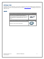
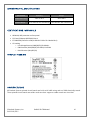
CABLES
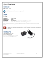
USB Type A to USB Type B, 72" in Length - Device Cable (Item# CA179)
The CA179 is a 72" standard USB device cable that
connects USB peripherals with a Type B connector to the
Type A connector on a host computer. The CA179 is USB
2.0 compliant and is compatible with USB 1.1 and 1.0
devices.
CAT5 Patch Cable, 7' in Length – Blue (Item# CA246)
Standard 7' CAT5 UTP Patch Cable (RJ45).
©Sealevel Systems, Inc.
SL9259 6/2015
SeaPAC R9-7R Manual
8
Product Overview
SPECIFICATIONS
PROCESSOR
Atmel (AT91SAM9G45) — 400MHz RISC Processor
32KB Data Cache, 32KB Instruction Cache, Write Buffer
Integrated Memory Management Unit (MMU)
MEMORY
128MB DDR2 RAM
256MB NAND Flash
DISPLAY
7” 300 nit TFT LCD with LED backlight
800 x 480 Resolution
16.7M Colors
TOUCHSCREEN
4-wire Resistive Touchscreen
BUS INTERFACES
10/100 BaseT Ethernet
1 USB Device Port (high retention)
1 USB 2.0 Port (high retention)
INDUSTRIAL I/O
Two Isolated RS-485 Ports
AUDIO
AC97 compatible Audio Codec with onboard speaker (WAV capable)
POWER
5 VDC Input
7.5 W Max
(TR146: 5 VDC @ 2.5 A power adapter included)
Power can be applied either through the dedicated input power connector or conveniently via COM A
connector (see Serial Communications section for details).
Use appropriately classified power supply marked Limited Power Source, or LPS. Follow local wiring
codes and regulations that may apply.
©Sealevel Systems, Inc.
SL9259 6/2015
SeaPAC R9-7R Manual
9
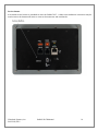
PRODUCT VIEWS
FRONT
BACK
©Sealevel Systems, Inc.
SL9259 6/2015
SeaPAC R9-7R Manual
10
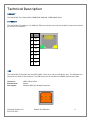
Technical Description
MEMORY
The SeaPAC R9-7R is offered with128MB DDR2 RAM and 256MB NAND Flash.
ETHERNET
The SeaPAC R9-7R includes a 10/100 BaseT Ethernet interface accessed via the RJ45 connector located on
the rear of the enclosure.
Pin
Signal
1
TX+
2
TX-
3
RX+
4
NC
5
NC
6
RX-
7
NC
8
NC
USB
The SeaPAC R9-7R provides one SeaLATCH USB 2.0 host port, and one USB device port. The USB ports are
located on the back of the enclosure. The USB device port is considered a DEBUG (maintenance) port.
Connector:
Manufacturer:
Description:
USB 2.0 Device Port
Samtec
Standard USB Type B (High Retension)
©Sealevel Systems, Inc.
SL9259 6/2015
SeaPAC R9-7R Manual
11
DISPLAY AND TOUCHSCREEN
The SeaPAC R9-7R features a 300 nit 7” TFT 800x480 pixel LCD with LED backlight, and a durable 4-wire
resistive touchscreen.
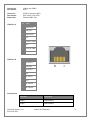
SERIAL COMMUNICATIONS
Connect to a variety of serial peripherals via the SeaPAC R9-7’s serial ports. Two isolated RS-485 serial
ports are provided, via RJ45 connectors, labeled “COM A” and “COM B” on the lower front panel of the unit.
RS485 interfaces are 2-Wire (Half-Duplex) with ECHO (capable of keeping the receiver always enabled and
able to echo back bytes transmitted on the differential line)
COM A port includes terminals to supply power to the unit (see pinout table below)
Use appropriately classified Limited Power Source, or LPS. Follow local wiring codes and regulations
that may apply.
©Sealevel Systems, Inc.
SL9259 6/2015
SeaPAC R9-7R Manual
12
Connectors:
Description:
COM A and COM B
RJ-45
Connector:
Description:
Mates with:
RS-485 Expansion (RJ45)
RJ45 Socket, W/O LEDs
Standard RJ45 Plug
COM Port A
COM Port B
Pin
Signal
1
5VDC Source
2
GND_ISO1
3
5VDC Source
4
485-
5
Common (GND)
6
485+
7
Common (GND)
8
Common (GND)
Pin
Signal
1
No connect
2
GND_ISO2
3
No connect
4
485-
5
No connect
6
485+
7
No connect
8
No connect
8
1
Assignments
Serial Port
Assignment
COM A
COM2 (USART1)
COM B
COM3 (USART2)
©Sealevel Systems, Inc.
SL9259 6/2015
SeaPAC R9-7R Manual
13
Service button
A recessed service button is provided to reset the SeaPAC R9-7. A blunt non-conductive instrument may be
used to press the button and assert a reset to the processor and peripherals.
©Sealevel Systems, Inc.
SL9259 6/2015
SeaPAC R9-7R Manual
14
Software
SEAPAC R9-7R QUICK START
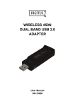
Remove the contents from the box.
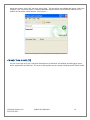
Insert the accompanying CD into your PC and run the installation program. This will install Talos Framework
binaries, documentation, and examples on your PC (See Figure 1.)
Figure 1. Installation Wizard
After installation, the package can be found in Windows by clicking Start All Programs Sealevel
Systems R9 Development.
The contents of the factory provided NAND Flash build will allow the SeaPAC R9-7R to run Windows CE 6.0
OS when power is applied to the board.
©Sealevel Systems, Inc.
SL9259 6/2015
SeaPAC R9-7R Manual
15
To avoid accidental damage, be sure to follow proper ESD procedures by grounding yourself and the
board.
Use a standard USB device cable and connect the Type B connector to the SeaPAC R9-7. Connect the cable’s
Type A connector into the host PC. (See Figure 2.)
Figure 2
You are now ready to set up a USB communication interface between the host PC and the SeaPAC R9-7.
Depending on which operating system you are using – Windows 7, Vista, or XP – the setup experience will
vary.
©Sealevel Systems, Inc.
SL9259 6/2015
SeaPAC R9-7R Manual
16
WINDOWS DEVICE CENTER
If your host PC is running Windows Vista or later and you are connected to the Internet, then Windows
Mobile Device Center software will install automatically. If you are not connected to the Internet but
have obtained the Windows Mobile Device Center software manually, then running their setup will
achieve the same result. (See Appendix A.)
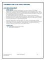
After installation, a negotiation will begin between the PC and the SeaPAC R9-7R board and the device
center connection screen will appear. (See Figure 3.)
Figure 3. Device Center Connected
Using your mouse, select “Connect without setting up your device”. The idea is to explore the file
system on the SeaPAC R9-7R without setting up synchronization with contacts, calendar, or e-mail. Now
choose “File Management Browse the contents of your device” from the screen. (See Figure 4.)
Figure 4. Device Center File Management
©Sealevel Systems, Inc.
SL9259 6/2015
SeaPAC R9-7R Manual
17
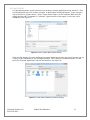
This action opens a standard Windows Explorer where the default file contents of the SeaPAC R9-7R can be
read or written to. (See Figure 5.)
Figure 5. Contents of SeaPAC R9-7
WINDOWS ACTIVESYNC FOR XP
If your host PC is running Windows XP, ActiveSync is required to establish connection to the SeaPAC R97. ActiveSync differs from Windows Mobile Device Center in that having an internet connection will not
establish an automatic download and installation. For installation procedures, refer to Microsoft’s
website. (See Appendix A). After installation, a negotiation will begin between the PC and the SeaPAC
R9-7R board, and the “New Partnership” dialog will appear. (See Figure 6.)
Figure 6. ActiveSync New Partnership Dialog
©Sealevel Systems, Inc.
SL9259 6/2015
SeaPAC R9-7R Manual
18
Using your mouse, select “No” and then select “Next”. The ActiveSync main dialog will appear. Select the
“Explore” icon. This action opens a standard Windows Explorer where the default file contents of the
SeaPAC R9-7R can be read or written. (See Figure 7.)
Figure 7. ActiveSync Main Dialog
CONNECTION COMPLETE
You are now ready to set up a complete development environment for building and debugging smart
device applications and libraries. The next section guides you by example using Microsoft Visual Studio.
©Sealevel Systems, Inc.
SL9259 6/2015
SeaPAC R9-7R Manual
19
PROGRAMMING USING THE .NET COMPACT FRAMEWORK
APPLICATION DEVELOPMENT
INTRODUCTION
With .NET Compact Framework coupled with our Talos .NET Framework, C# and VB.NET
programmers can develop powerful embedded applications on the SeaPAC R9-7R such as mobile,
robotics, home automation, industrial, and a broad range of other embedded applications. The low
cost of licensing for Windows 6.0 CE has created an ideal environment to develop a new generation
of embedded products around the SeaPAC R9-7.
Our Talos Framework allows access to the more specific I/O sections of the SeaPAC R9-7R
development board such as digital output points, CAN bus, and the serial ports. A complete list of
the API documentation can be found either in Windows by clicking Start All Programs Sealevel
Systems R9 Development Talos Documentation.html.
Writing .NET applications for the SeaPAC R9-7R is very similar to writing desktop or console
applications for XP and Vista. The only difference is the amount of resources available. Because the
memory footprint is smaller compared to a desktop computer, care should be taken where
allocation of memory is concerned, such as large object creation.
REQUIREMENTS
• Visual Studio Professional 2005 or 2008
•
.NET Compact Framework 3.5
©Sealevel Systems, Inc.
SL9259 6/2015
SeaPAC R9-7R Manual
20
GETTING STARTED
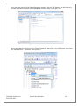
For this demonstration, we will construct a smart device console application using Visual C#. Start
Visual Studio and select File New Project. A ‘New Project’ dialog will appear. Select a project
type of Visual C# Smart Device. Select ‘Smart Device Project’ as the Template. Make sure the
combo box has .NET Framework 3.5 selected. Type the name of the project. In this case, call it
HelloWorld. (See Figure 8.)
Figure 8. Visual Studio New Project Dialog
Click the "OK" button. The next configuration screen allows you to select the type of project you are
creating. Select "Windows CE" for the target platform, .NET Compact Framework version 3.5 and
select the "Console Application" icon for the template. (See Figure 9.)
Figure 9. Visual Studio Add Smart Device Dialog
©Sealevel Systems, Inc.
SL9259 6/2015
SeaPAC R9-7R Manual
21
Once you have selected all of the configuration options, click the "OK" button. You will now see a
console application template called HelloWorld in Visual Studio. (See Figure 10.)
Figure 10. Visual Studio Main Window
We can now add the references to the Talos Framework. Right click on the “References” and select
the "Add Reference…" selection. (See Figure 11.)
Figure 11. Adding References to Project
©Sealevel Systems, Inc.
SL9259 6/2015
SeaPAC R9-7R Manual
22
An ‘Add Reference’ dialog will appear. Click on the ‘Browse’ tab then search for the installed library
path “C:\Program Files\Sealevel Systems\R9 Development\Assemblies”. If you don’t see a list of the
R9 libraries as shown in Figure 12, then refer to the SeaPAC R9-7R QuickStart section for software
installation details. While holding down the CTRL key, click on both "SLCorLib.dll" and "Talos.dll".
Click the “OK” button. (See Figure 12.)
Figure 12. Core Library References
Both DLLs should appear in your “References” list. (See Figure 13.)
Figure 13. Verification of Added Library References
©Sealevel Systems, Inc.
SL9259 6/2015
SeaPAC R9-7R Manual
23
Now that the Talos Framework has been referenced, you have access to all the I/O points exposed
on the SeaPAC R9-7R device.
For this simple HelloWorld application, we will just echo the string “Hello World” in the console
window. This can be accomplished by adding the following code to the automatically created
Program::Main() method. This code will echo “Hello World” and then pause for 5 seconds.
static void Main(string[] args)
{
Console.WriteLine("Hello World");
System.Threading.Thread.Sleep(5000);
}
From Visual Studio’s menu bar, select “Build Build HelloWorld”. After the build process has
completed select from the same menu bar, “Build Deploy HelloWorld”. A “Deploy HelloWorld”
dialog will appear for you to choose the appropriate target. Choose “Windows CE Device” then press
the ‘Deploy’ button. (See Figure 14.)
Figure 14. Choose Windows CE Device and Deploy
After the deployment phase, select “Debug->Start Without Debugging” from the Visual Studio menu
bar. A console will appear to display the ”Hello World” message. After 5 seconds, the window will
automatically close.
Examples can be found from the installation directory under ‘..\R9 Development\Samples\C#’ and
‘..\R9 Development\Samples\VB.NET’.
©Sealevel Systems, Inc.
SL9259 6/2015
SeaPAC R9-7R Manual
24
APPLICATION DEBUGGING
INTRODUCTION
This guide details the process of debugging an application developed for the SeaPAC R9-7R embedded
IO system. The SeaPAC R9-7R development platform easily integrates into standard Microsoft
development tools to make the debugging process extremely easy. The following sections detail the
requirements to begin debugging an application on Microsoft Windows 7, Vista, or XP.
REQUIREMENTS
•
Microsoft Windows Mobile Device Center using Vista or ActiveSync using XP
•
Microsoft Visual Studio Professional 2005 or 2008
•
USB Cable or Ethernet connection
Debugging your SeaPAC R9-7R applications is a simple process that requires a USB cable or Ethernet
connection, Microsoft device synchronization software, and Visual Studio. Depending on your version of
Windows, you will need to follow a different process to install the device synchronization software as
outlined in the SeaPAC R9-7R Quick Start section.
DEBUGGING AN APPLICATION
Once the SeaPAC R9-7R has been successfully attached to your PC, it is easy to begin debugging an
application on the SeaPAC R9-7. This section will demonstrate how to attach the Microsoft Visual Studio
debugger to the SeaPAC R9-7, show the use of breakpoints in the debugger, and show how to access
useful information while debugging an application.
We will be using the GPIO example application found in the "samples" directory of the Talos Framework
installation. The same methods will apply to any application you wish to debug on the SeaPAC R9-7.
©Sealevel Systems, Inc.
SL9259 6/2015
SeaPAC R9-7R Manual
25
ATTACH THE DEBUGGER
Once your solution is opened, it is necessary to specify the device target that you would like to use in
conjunction with the debugger. The default option is an emulator. Select "Windows CE Device" from the
target device drop down. (See Figure 15.)
Figure 15. Device Target Selection
If you would like to use the faster Ethernet connection for debugging instead of the USB connection,
refer to Appendix B.
©Sealevel Systems, Inc.
SL9259 6/2015
SeaPAC R9-7R Manual
26
Now select the “Connect to Device” icon to initiate synchronization between Visual Studio and the
SeaPAC R9-7R device. (See Figure 16.)
Figure 16. Connect to Device Icon
You should now see a connection dialog appear. (See Figure 17.)
Figure 17. Connection Status Dialog
©Sealevel Systems, Inc.
SL9259 6/2015
SeaPAC R9-7R Manual
27
BREAKPOINTS
Setting breakpoints allows you to stop execution of your application at any point and examine the state
of the application. A breakpoint may be set by selecting a line and pressing the "F9" hotkey. (See Figure
18.)
Figure 18. Breakpoint Selection
To begin debugging the application, click the "Start Debugging" button. (See Figure 19.)
Figure 19. Run Debugger Icon
©Sealevel Systems, Inc.
SL9259 6/2015
SeaPAC R9-7R Manual
28
Although you previously set up the target device, upon starting the first debug session, you will be
prompted to select the device to deploy the application to. Select the "Windows CE Device" as was done
earlier when selecting the target. (See Figure 20.)
Figure 20. Target Deployment Dialog
Once the application is deployed to the SeaPAC R9-7, it will begin execution. As soon as the first
breakpoint is reached, execution will cease and you will gain full control over the running application.
You may use the debugging options to continue execution, execute a single line, or execute multiple
lines. You may view the status of each variable by either hovering over it with the cursor or by
examining the windows at the bottom of Visual Studio just as you would with a desktop application.
(See Figure 21.)
Figure 21. Examining Program Variables
©Sealevel Systems, Inc.
SL9259 6/2015
SeaPAC R9-7R Manual
29
WATCHING VARIABLES
When program execution is halted due to a break point condition being met, the debugger will display
the state of all local variables. In addition to those variables, class specific variables can be grouped
together as a view to aid in debugging your application. This is accomplished by right clicking on a
variable and selecting "Add Watch". Each addition appends a tab to the “Watch n” window where n is
incremented for each variable added. (See Figure 22.) Each watch window provides a convenient tree
type structure for viewing hierarchical class variables.
Figure 22. Watch View
©Sealevel Systems, Inc.
SL9259 6/2015
SeaPAC R9-7R Manual
30
TARGET DEPLOYMENT AND EXECUTION
After your application is built using Visual Studio, either a debug or release executable, it may be desirable
to copy it into NAND Flash. This would provide a means to store and execute your application without the
need for connectivity to a host computer. The first step is transferring your application to a suitable
directory in the on-board NAND Flash. To accomplish this you will need to establish connectivity via
Windows Mobile Device Center or ActiveSync as outlined in the SeaPAC R9-7R Quick Start section above.
Figure 23. Application Placement
The SeaPAC R9-7R Runtime image comes pre-loaded with a utility program called “SpringBoard”. This utility
provides a solution for automatically running your applications at startup. Rather than copying your
application files to ‘/Windows/Startup/’ – which is in volatile memory – the executables should be copied to
`/nandflash/startup/’. After Windows CE runs, SpringBoard automatically starts applications in this startup
directory.
SpringBoard also provides a way to specify program arguments by supplying an XML configuration file. You
will need to create a simple XML file called “startup.xml”. This XML file should consist of an element list
each with an application name and the desired arguments for that application. (See Figure 24.) This file
must reside in the following location ‘/nandflash/startup/startup.xml’.
If the startup.xml file is not found or is not desired, SpringBoard will still automatically run all the
applications placed in the aforementioned directory structure, only no arguments will be passed to
those applications.
<?xml version="1.0" encoding="utf-8" ?>
- <programs>
<program name="sample1.exe" arguments="/i 1019 /w JSmith" />
<program name="sample2.exe" arguments="-e 2000" />
<program name="sample3.exe" arguments="/help" />
</programs>
Figure 24. startup.xml
©Sealevel Systems, Inc.
SL9259 6/2015
SeaPAC R9-7R Manual
31
BOOT SEQUENCE
Upon power-up, the SeaPAC R9-7R follows a specific boot sequence. The initial sequence is “firstboot”. The
firstboot process initializes the low level hardware and is responsible for loading the next sequence called
“eboot”. Eboot provides a configuration menu for setting connection types and start up memory locations.
Connection types include Ethernet and USB. Memory location is NAND Flash. Ultimately, eboot attempts to
load and execute the OS runtime image based on the configuration settings found here.
The SeaPAC R9-7R development board checks the raw data in the NAND Flash for a valid Eboot boot loader
(eboot.nb0).
The SeaPAC R9-7R ships with a NAND Flash programmed with the OS binaries listed below:
•
FIRSTBOOT.nb0
•
Eboot.nb0
•
NK.nb0
OS FILE RESTORATION
In the event that Sealevel produces updated OS file versions or a restore is desired, the OS files will need to
be programmed to the NAND Flash. Please see the section labeled “Upgrading the OS runtime image on
NAND Flash” below for more detail. The NAND Flash cannot be programmed until the existing OS runtime
image has been removed. This can be accomplished through the debug port as described in the following
section.
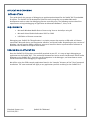
UPGRADING THE OS RUNTIME IMAGE ON NAND FLASH
Factory OS runtime images are stored in the “Boot Files” directory of the R9 Development installation (see
Quick start guide). The OS runtime image present in the NAND Flash is programmed through the USB
device port connection. Prior to programming an OS runtime, the existing image must be erased. The
procedure to erase the NAND Flash is documented in the Debug Port section.
Once the NAND Flash has been erased, use a standard USB device cable and connect the Type B connector
to the USB device port labeled Debug. Connect the Type A connector into the host PC. (See Figure 30.)
©Sealevel Systems, Inc.
SL9259 6/2015
SeaPAC R9-7R Manual
32
Figure 30. Type B USB Connector
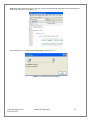
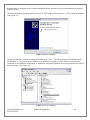
In Microsoft Windows 7, the device is recognized as a GPS camera and will typically enumerate as a COM
port. Verify the numeric assignment of the COM port in the device manager to determine the COM#
associated with the device. If prompted with the Found New Hardware Wizard, install the driver using the
following steps (Microsoft Windows XP dialog boxes are shown, other Microsoft Windows operating systems
are similar). If your operating system prompts you to search Windows Update, choose “No, not this time”.
Then, in the Found New Hardware Wizard, choose "Install from a list or specific location" and click Next.
(See Figure 31.)
Figure 31. Found New Hardware Wizard
Select "Search for the best driver in these locations" and check "Include this location in the search". Use the
©Sealevel Systems, Inc.
SL9259 6/2015
SeaPAC R9-7R Manual
33
Browse button to navigate to the “Utilities\SAM-BA\XP driver” directory of the R9 Development installation
and click “Next”.
The driver should be installed, and will come in as "AT91 USB to Serial Converter." Click Finish to complete.
(See Figure 32.)
Figure 32. Driver Installed
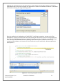
Determine COM port assignment using Device Manager > Ports. The USB function port should be listed.
For Windows 7, it may be listed as a GPS camera, otherwise it should be “AT91 USB to Serial Converter.”
Take note of the COM port assignment, to modify the programming batch file used to program the new OS
Runtime image. (See Figure 33.)
Figure 33. AT91 COM Port
©Sealevel Systems, Inc.
SL9259 6/2015
SeaPAC R9-7R Manual
34
Sample scripts have been provided in the R9 Development installation to automate the process of writing a
complete OS runtime to the device. The script is configured to target a device attached to COM49 by
default. This can be modified simply by editing the comport variable in the “NAND Program.bat” batch file.
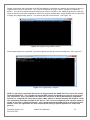
Once the batch file has been updated to reflect your system configuration, simply double-click the batch file
to begin the programming process. The process will take a few minutes. (See Figure 34).
Figure 34. Programming NAND (COM17)
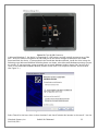
Once programming has completed, cycle device power and the OS runtime should boot. (See Figure 35.)
Figure 35. Programming Complete
NOTE: As previously mentioned the process of programming the NAND Flash first erases all content
from the NAND Flash. This includes the unique MAC address assigned to your device at the factory.
The “finalize.exe” tool is provided in the “Boot Files” directory of the R9 Development installation.
Finalize is a command line utility that accepts a MAC address in dashed notation (00-0A-0B-16-12-34).
The application should be executed on the device – this can be accomplished with rapistart, telnet, or
locally in the device’s Command Prompt - after reprogramming the NAND Flash to reassign the MAC
address. Once the application has been executed, the setting is applied upon device restart and
persists.
©Sealevel Systems, Inc.
SL9259 6/2015
SeaPAC R9-7R Manual
35
NETWORK CONFIGURATION
The Windows CE that runs on the SeaPAC R9-7R is initially configured obtain its IP address via DHCP.
Settings may be required for DNS or WINS server IP addresses or if you want to set up a static IP address.
We have included an application in the OS that enables device configuration through a simple XML file
format. The configuration is stored in a file that is kept up-to-date on the NAND Flash of the device.
Likewise, edits to this file can be read as requests to modify the device’s configuration. The configuration
file can be accessed through ActiveSync using the USB device port connection or through an FTP client if
you already know the IP address of the device. This section defines the XML configuration structure and
corresponding values applicable for each element of the structure. Throughout this section the following
definitions apply:
Term
Definition
Example
[int]
A number
123
[String]
Series of printable characters
This is a test string!234567609
[Multi-line String]
strings separated by \r\n
A\r\nNew\r\nMulti-liner
[Version]
A version number
1.2.3.4
[Boolean]
A binary state
True / False
[MACAddress]
A hardware identifier
00-0A-0B-16-11-1A
[IPAddress]
An IPv4 network address
192.168.0.100
©Sealevel Systems, Inc.
SL9259 6/2015
SeaPAC R9-7R Manual
36
The act of writing a new configuration file to the device will trigger a scan of that file (approximately
every 5 seconds). If the file is invalid, it will be replaced with the current configuration. If a single
element is invalid, that element and corresponding elements will be replaced with default values.
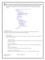
To apply a new configuration, use the <Action> element with a value of "apply" as documented
below.
Sample configuration.xml read from device.
<Configuration> -Structure
The configuration element is the root XML element. This element must be present or the configuration file will not be
considered valid. Invalid configurations will be replaced with a default configuration.
<System> -Structure
The system element contains all of the system information elements. This element must be present or the configuration
file will not be considered valid.
<OS> - Readonly [string]
The OS element contains a string representation of the Operating System name. In the case of R9 products, this will
be equivalent to "WinCE".
<Version> - Readonly [version]
The version element contains a dot-notation version string. This version is associated with the Operating System
element.
<Runtime> - Readonly [string]
This element contains a string representation of the specific OS Runtime Image.
<RuntimeVersion> - Readonly [version]
This element contains a dot-notation version string. This version is associated with the OS Runtime Image.
©Sealevel Systems, Inc.
SL9259 6/2015
SeaPAC R9-7R Manual
37
<Processor> - Readonly [string]
This element contains a Processor Identification string.
<Name> - Read/Write [string]
This element may contain the device name string. This identifier is used as the WinCE host name.
<Description> - Read/Write [string]
This element may contain the device description string. This element can be used to further identify a device.
<Owner> - Read/Write [string]
This element may contain a string that can be used to identify a person or department responsible for maintaining a
device.
<Company> - Read/Write [string]
This element may contain a string that can be used to identify the Company to which the device Owner is
associated.
<Address> - Read/Write [multi-line string]
This element may contain a multi-line string (\r\n separated) to identify the location of the device Owner.
<Phone> - Read/Write [string]
This element may contain a string representation of a telephone contact number for the device Owner.
<Extension> - Read/Write [string]
This element may contain a string representation of a telephone extension for the device Owner.
<Ethernet> - Structure
The Ethernet element contains a list of Ethernet interfaces available to the device.
<Interface name=""> - Structure (Attribute Readonly [string])
The interface element is a container for the interface settings that are specific to the interface identifiable as
"name". The name attribute is readonly and is used to uniquely distinguish Interface settings for the case where
there are multiple Ethernet interfaces available.
<DHCP> - Read/Write [Boolean]
This element contains a Boolean value indicating whether DHCP Address resolution is enabled or disabled.
Valid values are True or False.
<MAC> - Readonly [MACAddress]
This element contains a dash delimited string containing the unique MAC address of this interface. The first
3 octets identify the device as a Sealevel product (00-0A-0B). The fourth octet can be used to determine the
product family (16). And the last two octets will be unique for each device (11-1A).
<IPAddress> - Read/Write [IPAddress]
This element may contain the current DHCP acquired IP Address or the current static IP address depending
on the state of the DHCP element. Assigning a value to this element when DHCP is enabled has no effect.
<Subnet> - Read/Write [IPAddress]
This element may contain the current DHCP acquired Subnet Mask or the current static Subnet Mask
depending on the state of the DHCP element. Assigning a value to this element when DHCP is enabled has
no effect.
©Sealevel Systems, Inc.
SL9259 6/2015
SeaPAC R9-7R Manual
38
<Gateway> - Read/Write [IPAddress]
This element may contain the current DHCP acquired Gateway address or the current static Gateway address
depending on the state of the DHCP element. Assigning a value to this element when DHCP is enabled has
no effect.
<Wifi enabled=""> - Structure (Attribute Readonly)
The Wifi element is a container for wireless bridge settings if such a bridge is present. The "enabled"
attribute will reflect whether the Interface is able to communicate with an approved wireless bridging
module.
<SSID> - Read/Write [string]
This element contains the SSID string to be used when forming the wireless connection.
<Mode> - Read/Write [string: Adhoc, Infrastructure]
This element contains the overall Wireless configuration mode.
<Channel> - Read/Write [int: 1,11]
This element contains the wireless channel offset to use in Adhoc mode.
<Security> - Read/Write [string: None, WepOpen64, WepOpen128, WepShared64, WepShared128,
WpaTkip, Wpa2Aes, Wpa2Tkip]
This element contains the security method for use in establishing the wireless connection.
<Key encoding=""> Writeonly [string] (Attribute [string: Hex, Ascii, Pass])
This key is used to set the wireless connection passphrase or value. Depending on the wireless
configuration, the "encoding" attribute will need to be set accordingly. For security purposes this
value cannot be read once it has been set.
<Action> - Writeonly [string]
This element may be used to trigger predetermined device behavior. For example, setting a value of "apply" to this
element will result in the specified configuration being applied to the hardware and trigger a device restart so the settings
will take effect.
©Sealevel Systems, Inc.
SL9259 6/2015
SeaPAC R9-7R Manual
39
Specifications
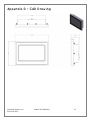
DIMENSIONS
8”W x 5.5”H x 1.75”L
For CAD drawing with dimensions, see Appendix D.
POWER
5 VDC Input
7.5 W Max
Connector:
Manufacturer:
Part Number:
Description:
Mates with:
5 VDC / GND
Molex
39-29-9029
Mini-Fit Jr.Header, Snap-In Plastic Peg PCB Lock, 2 Circuits
Molex 39-01-2020, 39-01-3022 Male locking connector
Power can also be conveniently supplied via COM A connector (see Serial Communications section for
details).
Use appropriately classified Limited Power Source, or LPS. Follow local wiring codes and regulations
that may apply.
POWER ADAPTER
100-240VAC 50/60Hz input
5 VDC 2.5 A LPS output
0º to 40º C operating temperature range
Molex 39-01-2020 locking connector
©Sealevel Systems, Inc.
SL9259 6/2015
SeaPAC R9-7R Manual
40
ENVIRONMENTAL SPECIFICATIONS
Specification
Operating
Storage
Temperature Range
-30ºC to 70º C
-40º to 80º C
10 to 90% R.H. Non-Condensing
10 to 90% R.H. Non-Condensing
Humidity Range
CERTIFICATIONS / APPROVALS
•
•
•
•
NEMA 4X, IP65 protection on front panel
FCC Part15 Subpart B/ICES 003 Class A
ETL 4000758 (conforms to EN/UL 61010-1 & CSA C22.2 No 61010-1)
CE marking
o Low Voltage Directive (2006/95/EC) EN 61010-1
o EMC Directive (2004/108/EC) EN 55022, EN 55024
o RoHS Directive (2011/65/EU)
PRODUCT MARKING
MANUFACTURING
All Sealevel Systems printed circuit boards are built to UL 94V0 rating and are 100% electrically tested.
These printed circuit boards are solder mask over bare copper or solder mask over tin nickel.
©Sealevel Systems, Inc.
SL9259 6/2015
SeaPAC R9-7R Manual
41
Appendix A – Resources
BOOKS
Professional Microsoft Windows Embedded CE 6.0, Wrox, Phung.
http://it-ebooks.info/book/1461/
Programming Windows Embedded CE 6.0 Developer Reference, Microsoft Press, Boling.
https://www.microsoft.com/learning/en-us/book.aspx?id=11064Web Sites
WEBSITES
Atmel SAM-BA In-System Programmer (ISP)
http://www.atmel.com/tools/atmelsam-bain-systemprogrammer.aspx
FileZilla Open-Source FTP Client
http://www.filezilla-project.org
Microsoft Windows Embedded Home Page
http://www.microsoft.com/windowsembedded/en-us/windows-embedded.aspx
Microsoft Windows Embedded CE 6.0 Online Documentation
https://msdn.microsoft.com/en-us/library/ee504812(v=winembedded.60).aspx
Microsoft ActiveSync Download
http://www.microsoft.com/windowsmobile/en-us/help/synchronize/ActiveSync-download.mspx
Microsoft Mobile Device Center 6.1
https://support.microsoft.com/en-us/kb/931937
Microsoft .NET Compact Framework
https://msdn.microsoft.com/en-us/library/ms376787.aspx
PuTTy Telnet/SSH Client Application
http://en.wikipedia.org/wiki/PuTTY
©Sealevel Systems, Inc.
SL9259 6/2015
SeaPAC R9-7R Manual
42
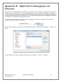
Appendix B – Application Debugging over
Ethernet
Applications can be debugged over an Ethernet connection in place of USB by configuring Visual Studio to
directly connect to your device. For this method to work properly, the Ethernet connection to the device
must be properly configured to allow normal TCP/IP communications and you must know the IP address of
the device you wish to execute the application on. For further information about configuring the Ethernet
of the device see the Network Configuration section.
To configure Visual Studio to use your device for debugging over Ethernet, click the “Device Options”
button on the Device toolbar. See below.
On the “Device Options” dialog, select the “Windows CE” platform and click the “Properties…” button. See
below.
On the “Windows CE Device” properties dialog click the “Configure…” button. See below.
©Sealevel Systems, Inc.
SL9259 6/2015
SeaPAC R9-7R Manual
43
Now click the “Use specific IP address” radio button and type the IP address of the device in the text box.
See below.
Click the “OK” button on all of the dialog windows and you should now be able to connect to the device
through Ethernet for debugging. The application debugging guide can be continued as normal.
©Sealevel Systems, Inc.
SL9259 6/2015
SeaPAC R9-7R Manual
44
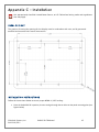
Appendix C – Installation
Use appropriately classified Limited Power Source, or LPS. Follow local wiring codes and regulations
that may apply.
PANEL CUT OUT
The process of cutting the opening for the display must be undertaken with care, and by personnel
qualified and experienced in panel construction.
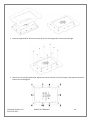
INSTALLATION INSTRUCTIONS
Follow the instructions below to ensure proper NEMA 4 / IP65 sealing:
•
Place the SeaPAC R9-7R in position; the ten studs go through the ten holes on the panel mounting plate (see
figures below)
©Sealevel Systems, Inc.
SL9259 6/2015
SeaPAC R9-7R Manual
45
•
Place the supplied 6/32" KEP nuts on each of the ten mounting studs. Fasten only hand tight.
•
After the unit is properly positioned, tighten the nuts to 0.56 Nm (5 in lb) of torque in the sequence pictured
below. Do not overtighten.
©Sealevel Systems, Inc.
SL9259 6/2015
SeaPAC R9-7R Manual
46
Appendix D – CAD Drawing
©Sealevel Systems, Inc.
SL9259 6/2015
SeaPAC R9-7R Manual
47
Appendix E – How to Get Assistance
When calling for technical assistance, please have the device installed and ready to run diagnostics. If
possible, have your user manual and current settings ready.
The Sealevel website is an excellent resource located at www.sealevel.com. The most current software
updates and user manuals are available via our homepage by clicking on the 'Drivers' or 'Manuals' links
located under ‘Technical Support.’ Manuals and software can also be downloaded from the product page
for your device.
The FAQ section of our website answers many common questions. Refer to this helpful resource by visiting
www.sealevel.com/faq.asp.
TECHNICAL SUPPORT
Monday – Friday
8:00 am to 5:00 pm EST
Phone: +1 (864) 843-4343
Email: [email protected]
RETURN AUTHORIZATION MUST BE OBTAINED FROM SEALEVEL SYSTEMS BEFORE RETURNED
MERCHANDISE WILL BE ACCEPTED. AUTHORIZATION CAN BE OBTAINED BY CALLING SEALEVEL
SYSTEMS AND REQUESTING A RETURN MERCHANDISE AUTHORIZATION (RMA) NUMBER.
©Sealevel Systems, Inc.
SL9259 6/2015
SeaPAC R9-7R Manual
48
Warranty
Sealevel's commitment to providing the best I/O solutions is reflected in the Lifetime Warranty that is
standard on all Sealevel manufactured I/O products. Relio™ industrial computers are warranted for a period
of two years and the R9 family is warranted for a five year period from date of purchase. We are able to
offer this warranty due to our control of manufacturing quality and the historically high reliability of our
products in the field. Sealevel products are designed and manufactured at its Liberty, South Carolina
facility, allowing direct control over product development, production, burn-in and testing. Sealevel
achieved ISO-9001:2000 certification in 2002.
Warranty Policy
Sealevel Systems, Inc. (hereafter "Sealevel") warrants that the Product shall conform to and perform in
accordance with published technical specifications and shall be free of defects in materials and
workmanship for the warranty period. In the event of failure, Sealevel will repair or replace the product at
Sealevel's sole discretion. Failures resulting from misapplication or misuse of the Product, failure to adhere
to any specifications or instructions, or failure resulting from neglect, abuse, accidents, or acts of nature
are not covered under this warranty.
Warranty service may be obtained by delivering the Product to Sealevel and providing proof of purchase.
Customer agrees to insure the Product or assume the risk of loss or damage in transit, to prepay shipping
charges to Sealevel, and to use the original shipping container or equivalent. Warranty is valid only for
original purchaser and is not transferable.
This warranty applies to Sealevel manufactured Product. Product purchased through Sealevel but
manufactured by a third party will retain the original manufacturer's warranty.
NON-WARRANTY REPAIR/RETEST
Products returned due to damage or misuse and Products retested with no problem found are subject to
repair/retest charges. A purchase order or credit card number and authorization must be provided in order
to obtain an RMA (Return Merchandise Authorization) number prior to returning Product.
HOW TO OBTAIN AN RMA (RETURN MERCHANDISE AUTHORIZATION)
If you need to return a product for warranty or non-warranty repair, you must first obtain an RMA number.
Please contact Sealevel Systems, Inc. Technical Support for assistance:
Available
Phone
Email
Monday – Friday, 8:00AM to 5:00PM EST
864-843-4343
[email protected]
©Sealevel Systems, Inc.
SL9259 6/2015
SeaPAC R9-7R Manual
49