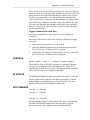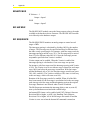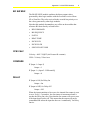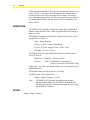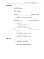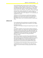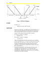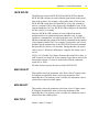
1
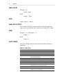
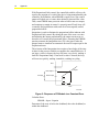
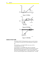
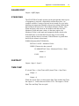
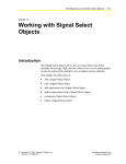
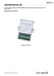
FANs 637.5, 1637.5 Appendix Section Issue Date 0400 APPLICATION NOTE Appendix C: HVAC PRO Modules HVAC PRO Modules .............................................................................3 Introduction........................................................................................................*3 Key Concepts.....................................................................................................*4 ABS VALUE.................................................................................................................... 6 ADD................................................................................................................................ 6 ANALOG OUTPUT ......................................................................................................... 6 AND................................................................................................................................ 6 AUTO ZERO................................................................................................................... 6 AVERAGE ...................................................................................................................... 7 BI UPDATE..................................................................................................................... 7 BIN COMMAND.............................................................................................................. 7 BINARY MUX ................................................................................................................. 8 BO HW MUX .................................................................................................................. 8 BO SEQUENCE ............................................................................................................. 8 BO SW MUX................................................................................................................... 9 CFM CALC ..................................................................................................................... 9 COMPARE ..................................................................................................................... 9 DELAY............................................................................................................................ 9 DERIVATIVE ................................................................................................................ 10 DIVIDE ......................................................................................................................... 10 ENTHALPY................................................................................................................... 11 FAILSOFT .................................................................................................................... 11 FAST BO ...................................................................................................................... 12 * Indicates those sections where changes occurred since the last printing. © 2000 Johnson Controls, Inc. Code No. LIT-6375190 www.johnsoncontrols.com 2 Appendix FLT TO INT .................................................................................................................. 12 HEATPUMP.................................................................................................................. 12 HTG/CLG PI ................................................................................................................. 13 IF SKIP ......................................................................................................................... 14 INCR W FB................................................................................................................... 14 INCR WO FB ................................................................................................................ 15 MAX SELECT............................................................................................................... 15 MIN SELECT ................................................................................................................ 15 MULTIPLY .................................................................................................................... 15 MUX ............................................................................................................................. 16 NEG COMPARE........................................................................................................... 16 NOT.............................................................................................................................. 16 OR ................................................................................................................................ 16 OS RESET ................................................................................................................... 16 RAMP ........................................................................................................................... 17 RESET ......................................................................................................................... 17 SINGLE PI .................................................................................................................... 17 SINGLE POINT CMD.................................................................................................... 20 SQUARE ROOT ........................................................................................................... 21 STAGE DIAG................................................................................................................ 21 SUBTRACT .................................................................................................................. 21 TIME COMP ................................................................................................................. 21 XOR.............................................................................................................................. 22 * Indicates those sections where changes occurred since the last printing. Appendix C: HVAC PRO Modules 3 HVAC PRO Modules Introduction HVAC PRO applications are composed of the modules listed in this document. The basic function of each block is described, including how the outputs of the block are related to the inputs. 4 Appendix Key Concepts Table 1 and Table 2 list the modules included in this section. Descriptions of each module follow. Table 1: Basic Modules Module Category Module Name Math ADD DIVIDE MULTIPLY SUBTRACT Logical AND NOT OR XOR Compare COMPARE NEG COMPARE TIME COMPARE Calculations AVERAGE MAX SELECT MIN SELECT Multiplex BINARY MUX FAILSOFT MUX Miscellaneous ABS VALUE FLT TO INT SQUARE ROOT Appendix C: HVAC PRO Modules Table 2: Complex Modules Module Category Module Name Direct Slot Outputs AUTO ZERO BIN COMMAND BO SEQUENCE FAST BO HEATPUMP INCR W FB INCR WO FB SINGLE POINT CMD STAGE DIAG Time Based Modules DELAY DERIVATIVE HTG/CLG PI SINGLE PI Calculations CFM CALC ENTHALPY RAMP RESET OS Modules ANALOG OUT BI UPDATE BO HW MUX BO SW MUX IF SKIP OS RESET 5 6 Appendix ABS VALUE IF (Input >= 0) Output = Input ELSE Output = - Input ADD Output = Input 1 + Input 2 ANALOG OUTPUT The ANALOG OUTPUT module causes the Analog Output (AO) values to be converted from 0% to 100% into 0 counts to 255 counts. AND IF (Input 1 = 1) AND (Input 2 = 1) Output = 1 ELSE Output = 0 AUTO ZERO The AUTO ZERO module becomes activated under the following conditions: Table 3: Auto Zero Condition Input Function Sensor Count Defines number of sensors to be auto zeroed. Sensor Input 1,2,..N Inputs from sensors Auto Zero Command An N2 or Zone Bus command that activates the Auto Zero command without delay. Auto Zero Enable Allows Auto Zero to execute conditionally. Actual Flow Calculated flow from sensor Max Flow Maximum design flow Min Flow Minimum design flow Auto Zero Duration Time required for full travel of the actuator plus some additional time to ensure positive shutoff. Output Auto Zero Status Indicates Auto Zero is active, used by other modules for initiating auto zero commands. Appendix C: HVAC PRO Modules 7 Once activated, the AUTO ZERO module sets the Auto Zero Status to On for the Auto Zero Duration. Other modules may use the Auto Zero status to turn off an output and command an actuator to zero percent. The flow is presumed to be zero when the Auto Zero Duration has expired. Each sensor is then read and the associated AI (Analog Input) offset table entry is updated so that the sensor value reads 0.005 units. The Auto Zero Duration time should be sufficient for the controlled device to close and the control variable to reach a steady state (allow for any input filtering). Trigger Conditions for Auto Zero Auto Zero command forces Auto Zero to execute regardless of conditions. Auto Zero enable must be On for the following conditions to trigger Auto Zero: ● ● ● Flow sensor goes negative as a result of drift. Auto Zero Enable has been On for at least one hour and actual flow is below the 1/3 Maximum Flow Setpoint. Twenty-four hours has passed since the last Auto Zero and actual flow is below the 1/3 Maximum Flow Setpoint. AVERAGE Output = (Input 1 + Input 2 + ... + Input N) / Number of Inputs The reliability of the AVERAGE operands is evaluated so that the average is only computed on the operands that are reliable. If all operands are unreliable, the average is still computed with unreliable values and the result is also flagged as unreliable. BI UPDATE The BINARY UPDATE module causes the binary inputs to read into memory which can be referenced by other logic modules. If the BI (Binary Input) is overridden, the override value will be read into memory instead of the actual hardware input value. BIN COMMAND First BO + 1 = First BO First BO + 2 = First BO .... First BO + N = First BO Each BO (Binary Output) is commanded to the value of the first BO. The BIN COMMAND maintains the interstage delays, min on, min off, and max cycles attributes associated with each BO. 8 Appendix BINARY MUX IF Selector = 1 Output = Input 1 ELSE Output = Input 2 BO HW MUX The BO HW MUX module causes the binary output values to be made available to the hardware driver firmware. The BO HW MUX module is tied directly to the hardware output. BO SEQUENCE The BO SEQUENCE monitors an analog output to control several stages of BOs. The interstage spacing is calculated by dividing 100% by the number of stages. The first stage may be specified and may be different from the other evenly spaced stages. For instance, with four stages total, the interstage spacing would be every 25%. The first stage may be moved from 25% to a different value like 10%. Note the first stage percent may not be specified when Vernier is enabled. Vernier output can be enabled. When the Vernier is enabled, the interstage spacing is calculated as if one extra stage was present. For instance, with four stages total, the interstage spacing with Vernier is 20%. The Vernier is set to zero when a stage is turned on, and ramps up to 100% just before the next stage is turned on. With four stages and the Monitored AO at 70%, the first three stages would come on at 20%, 40%, and 60%. The Vernier would be at 50% since it is half way to the next stage, which will come on at 80%. Rotation of the first stage can also be enabled. When all of the BOs have been turned off, the first stage is recalculated to be the next stage, each time up to the last stage and then beginning again at the original first stage. Rotation is not allowed when Vernier is enabled. The BO Sequencer maintains the interstage delays, min on, min off, max cycles attributes associated with each BO stage. An Instant OFF feature can be enabled with UNT (Unitary) firmware Revisions B00 or higher, or AHU (Air Handling Unit) firmware Revisions C06 or higher. All of the BO stages are turned off and the Vernier is set to zero when the Instant Off command is turned on. Appendix C: HVAC PRO Modules 9 BO SW MUX The BO SW MUX module combines the binary output values generated by other logic modules with the Overrides received from N2 or Zone Bus. The value received in the override has priority over the values generated by other logic modules. Note that this module does not have any effect on the modules that reference BO slots directly as listed below: ● BIN COMMAND ● BO SEQUENCE ● FAST B ● HEAT PUMP • INCR W FB ● INCR WO FB ● SINGLE POINT CMD CFM CALC Velocity = 4005 * SQRT (Air Pressure/K constant) CFM = Velocity * Duct Area COMPARE IF (Input 1 > Input 2) Output = 1 IF [Input 1 < (Input 2 - Differential)] Output = 0 DELAY IF (Input is ON) for Delay On Output = On IF (Input is OFF) for Delay Off Output = Off When the input transition to On occurs, the internal On counter is reset to zero. Every 1.5 second tic, the On counter is incremented until it reaches the Delay On value. Note that the On counter will reset to zero if the input drops back to off. This means that the output will not be commanded On unless the input has been on “continuously” for Delay On tics. 10 Appendix When the input transition to off occurs, the internal Off counter is reset to zero. Every 1.5 second tic, the Off counter is incremented until is reaches the Delay Off value. Note that the Off counter will reset to zero if the input jumps back to on. This means that the output will not be commanded Off unless the input has been off “continuously” for Delay Off tics. DERIVATIVE The DERIVATIVE module combines the output from a SINGLE PI module with a derivative term, which is proportional to the change in Error over time. The SINGLE PI module defined Error, Proportional Term (P Term), Integral Term (I Term) as: Error = Input - Setpoint P Term = [ 100% * (Error / Prop Band) ] I Term = (P Term / Integral Gain) + Last I Term PI Output = P Term + I Term The DERIVATIVE module defines the Delta Error and Derivative Term, D Term as: Delta Error = Error Now - Error Last Time D Term = [100% * (Delta Error / Prop Band) ] * [ Factor * (Derivative Gain/ Delta Time] Delta Time = 6.0 (This is the actual run time of 1.5 seconds times the default filter of 4.) The default sample rate for the input is 6 seconds. The PID output is then calculated as: Output = Single PI Output - D Term Note: The DERIVATIVE module does not accept an input, setpoint, and deadband like the SINGLE PI module does. The Error now must be calculated with separate logic using the SUBTRACT module. DIVIDE Output = Input 1 / Input 2 Appendix C: HVAC PRO Modules 11 ENTHALPY T = Temperature RH = Relative Humidity Units = 1 (Metric) Units = 0 (English) IF (units = 1) METRIC.....Kcal/Kg S1 = 0.000416 *T³ + 0.00227*T² + 0.323*T + 3.77 Enthalpy = 0.1 * S1 * 0.0597*RH + 0.24*T IF (units = 0) IF (temperature < 70.0) ENGLISH low temps...btu/lb S1 = -0.071 S2 = 0.241*T S3 = 0.000071*T² - 0.0043*T + 0.12 S4 = 0.000003*T - 0.00011 Enthalpy = S1 + S2 + S3*RH + S4*RH² ELSE ENGLISH hi temps......btu/lb S1 = 0.0 S2 = 0.2399*T S3 = 0.000107*T² - 0.00927*T + 0.293 S4 = 0.000005*T - 0.0003 Enthalpy = S1 + S2 + S3*RH + S4*RH² FAILSOFT IF Status input OR Controlled input are unreliable Failsoft Output = Failsoft Value ELSE Failsoft Output = Controlled Input Value 12 Appendix FAST BO The FAST BO module provides control for two Momentary BOs having consecutive addresses. The first BO is pulsed for 50 milliseconds for On operation. The second BO is pulsed for 50 milliseconds for Off operation. The Last Commanded State is saved to prevent the FAST BO from pulsing the desired BO every 1.5 second pass through the program. IF (On BO not equal to Last Commanded State) Last Commanded State = On BO IF (On BO = 1) Pulse the On BO ELSE Pulse the Off BO FLT TO INT This module converts a floating point value to an integer value with a range of 0 to 32767. Values are truncated if necessary. HEATPUMP The HEATPUMP module controls a Heat Pump based on the Heating Command and Cooling Command generated by other logic, i.e., the HTG/CLG PI module. A heat pump achieves heating or cooling with a single compressor and a reversing valve. The HEATPUMP module maintains the min on, min off, and max cycles attributes associated with the Compressor BO and the Reversing Valve BO. Each slot number provided in the HEATPUMP module points to a Compressor/Reversing Valve BO pair. The module allows the Number of Compressors to be specified. This value is usually set to 1 or 2. The mode of the HEATPUMP is set to cooling when the Cooling Command is non-zero and the Heating Command is zero. The mode is set to heating when the Heating Command is non-zero and the Cooling Command is zero. A critical module performed by HEATPUMP is control of the Reversing Valve. When switching from Heating Mode to Cooling Mode, the compressors must be off long enough for the refrigerant to settle before switching the flow with the Reversing Valve BO. The Reversing Valve Delay provides the number of 1.5 second tics to wait after the compressors have been turned off before commanding the Reversing Valve BO. The Reversing Valve Cmd tells the module how to command the Reversing Valve BO to switch to the correct mode. Appendix C: HVAC PRO Modules 13 The HEATPUMP module determines the percentage of Heating Command or Cooling Command at which to turn on each compressor by dividing 100% by the Number of Compressors. A Vernier similar to the BO SEQUENCE module is calculated internally to determine the duty cycle of each compressor. For example, with two compressors defined and the Cooling Command at 40%, the first compressor would be on 80% of the time and Compressor 2 would be off. When the Cooling command is above 50%, Compressor 1 is on continuously and Compressor 2 is cycled. The duty cycle of each compressor is usually altered internally to maintain the correct min on, min off, and max cycles defined in the BO database record. The Cycles per Hour value supplied to the HEATPUMP module is also recalculated internally to maintain these delays. HTG/CLG PI For an explanation of the terminology involved with the PI module, such Proportional Band, Integration Time, and Offset, see the Single PI Module description. The HTG/CLG PI combines heating and cooling PI loops into a single module. The SINGLE PI module is invoked with the combined Cooling and Economizer variables. The Cooling Sensor and Cooling Setpoint from the HTG/CLG PI are passed directly to the SINGLE PI module. The Cooling proportional band and the Economizer proportional band are combined before passing to the SINGLE PI. The output from the SINGLE PI is used to calculate the Cooling output and the Economizer output. The SINGLE PI module is invoked with the combined Heating and Preheat variables. If the Cooling Sensor and Heating Sensor are the same, then the integral terms are adjusted to provide correct operation. If the Heating Deadband is non-zero then the Heating Setpoint is calculated as an offset from the Cooling Setpoint, otherwise the Heating Setpoint is passed on directly to the SINGLE PI module. The Heating proportional band and the Preheat proportional band are combined before passing to the SINGLE PI. The output from the SINGLE PI is used to calculate the Heating output and the Preheat output. 14 Appendix Heating Preheat Economizer Cooling 100.0 % Output Command 0.0 % Heating Prop Band Preheat Prop Band Htg Deadband Htg Setpoint Econ Prop Band Clg Prop Band Clg Deadband Clg Setpoint HTGCLGPI Figure 1: HTG/CLG PI Module IF SKIP IF (Input 1 = 1) SKIP the next logic module function. INCR W FB The INCR W FB module, INCREMENTAL WITH FEEDBACK, is a simple control loop that monitors the offset between a Setpoint AO and a calculated feedback signal. The output drives an incremental actuator, which consists of an Open BO and a Close BO. IF (Setpoint - Feedback > Deadband) Open BO = On IF (Feedback - Setpoint > Deadband) Close BO = On When switching direction from drive open to drive close, both BOs will be commanded Off for 1.5 seconds. A Failsoft feature allows the INCR W FB to drive the BOs to a desired state when the Setpoint, Feedback or Deadband becomes unreliable. When the Failsoft command is 1, the Close BO is commanded On, otherwise the Open BO is commanded On. The INCR W FB also allows Full Open and Full Close override commands. If the Full Open value is 1, the Open BO will be commanded On. If the Full Close value is 1, the Close BO will be commanded On. If both Full Open and Full Close are 1, the output is determined by the Failsoft command. Appendix C: HVAC PRO Modules 15 INCR WO FB The difference between INCR WO FB and INCR W FB is that the INCR WO FB calculates its own feedback signal based on the stroke time of the actuator. For example, with a stroke time of 100 tics, the INCR WO FB would drive the Open BO for 40 tics (60 seconds) to achieve a setpoint of 40% after restart with a deadband of zero. If the setpoint changed to 50%, the INCR WO FB would drive the Open BO for only 10 tics (15 seconds). Since the INCR WO FB calculates its own feedback the actual position needs to be synchronized upon controller reset. A restart variable is commanded to zero upon controller reset. The INCR WO FB then commands the output to the Failsoft command for the number of tics found in Stroke Time. For example, if stroke time was 100 tics and the Failsoft command was 0, the INCR WO FB would command the Open BO for 100 tics (150 seconds). During this time, the restart value is set to 1. When the calibration is complete, the restart value is set to 2. UNT/VAV (Variable Air Volume) firmware Revision D02 or later, or AHU firmware revision C06 or later employs logic that overdrives the incremental actuator 1.5 times its stroke time when the command equals 0% or 100%. All other features operate the same as in the INCR W FB. MAX SELECT This module selects the maximum value from a list of N input values. If all inputs are unreliable, then it selects the maximum of the unreliable data. If at least one value is reliable, the maximum value is selected from only the reliable inputs. MIN SELECT This module selects the minimum value from a list of N input values. If all inputs are unreliable, then it selects the minimum of the unreliable data. If at least one value is reliable, the minimum value is selected from the reliable points. MULTIPLY Output = Input 1 * Input 2 16 Appendix MUX IF Selector = 1 Output Value = Input 1 Value Output Reliability = Input 1 Reliability ELSE Output Value = Input 2 Value Output Reliability = Input 2 Reliability NEG COMPARE IF (Input 1 < Input 2) Output = 1 IF [Input 1 > (Input 2 + Differential)] Output = 0 NOT IF (Input 1 = 1) Output = 0 ELSE Output = 1 OR IF (Input 1 = 1) OR (Input 2 = 1) Output = 1 ELSE Output = 0 OS RESET The OS RESET module causes the execution of the logic modules to start over at the first module after a 1.5 second delay. This is always the last module loaded. Appendix C: HVAC PRO Modules 17 RAMP The RAMP module allows an output point to track an input point in incremental steps over time. A fast and slow step size are allowed. When the output is near zero, the Slow Step size is used to increment the output every 1.5 seconds until it reaches the input. During the time the Slow Step is being used, the Step Flag will be set to 1. When the output becomes greater or equal to the input, the Fast Step increment is used and the Step Flag is set to zero. Anytime the difference between the input and the output is less than the current step size, the output will be set exactly equal to the input. Anytime the output gets near zero (below 0.001), the step size will change back to the slow step size. Disable the slow step feature by making the Fast Step equal to the Slow Step. The reliability of the output is based on the reliability of the input and any math errors that may occur when incrementing the output value. RESET Output = [(Input - Input Setpoint) * (Output Prop Band/Input Prop Band)] + Output Setpoint The output is limited to the output setpoint when the input falls below the input setpoint. Likewise, the output is limited to the end of the output proportional band when the input goes above the input proportional band. The reliability of the output is based on the reliability of the input and any math errors that may occur when incrementing the output value. SINGLE PI The SINGLE PI module provides closed loop control. The PI stands for Proportional and Integral. The proportional control is achieved by calculating the difference between the input and the desired setpoint. If the difference is greater than the deadband, the output is commanded to a value, which is proportional to the difference divided by the proportional band. With Proportional Only, the output would increase up to 100% as the input moved from the edge of the deadband up to the width of the proportional band. In other words, when the Error, which is equal to the Input minus the Setpoint (see Table 4), is equal to the Proportional Band, the Pterm output is equal to 100%. Proportional Only control causes an instantaneous response in the output based on the change in ERROR. 18 Appendix With Proportional Only control, the controlled variable will never be equal to the setpoint as a result of the device being manipulated by the controller. By definition, when ERROR is equal to zero, the control output will equal zero, or some other arbitrarily chosen offset value. Thus, some ERROR must persist in order to hold a non zero output, and continue to remain in control. A properly tuned P only loop will eventually find equilibrium with some error from setpoint, termed proportional offset. Integration is used to eliminate the proportional offset inherent with Proportional Only control. By taking the sum of the error over time and adjusting the output proportionally, the output can increase or decrease to overcome the proportional offset. Assuming the ERROR remains constant, the Integration time (TI) is the time it takes the Integral term to contribute an amount to the total PI output equal to the Proportional term. The selection of the Integration time requires a knowledge of the time it takes for the process variable to respond to the controlled device. If too large a value is chosen, the loop will react very slowly, making it look like Proportional Only. If too small a value is chosen, the loop will react too quickly, making it unstable, resulting in cycling. Error Integral Iterm Output PI Output Pterm Output Prop T1 Time CONSTERR Figure 2: Response of PI Module to a Constant Error Calculate Error: ERROR = Input - Setpoint Determine if the error is below the deadband, above the deadband, or within the deadband. Appendix C: HVAC PRO Modules 19 Table 4: Single PI ERROR Explanation If (ERROR < -Deadband) ERROR = ERROR + Deadband If the AI is below the setpoint by more than the deadband Else If (ERROR > Deadband) ERROR = ERROR - Deadband) If the AI is above the setpoint by more than the deadband Else ERROR = 0.0 Otherwise the AI is within the deadband. Table 5: Single PI Terminology Term Definition Input Process variable Setpoint The target value for the input controller Proportional Band Defined in the same units as the Input Deadband The area around the setpoint where no output change is required Integration Gain Time Integral time, defined in units of tics, where 1.5 seconds equals one tic Bias A user defined value. (See following paragraph for definition.) Pterm The part of the output due to the proportional Error Iterm The part of the output due to integration Output The command value to the controlled device The following table illustrates how the output of the PI controller is calculated: Table 6: PI Output Procedure Description Pterm = 100% * Err/PBand Calculate proportional part Output = Pterm + Iterm + Bias Add proportional part, last Iterm, and Bias If (Output > 100%) Output = 100% Limit the Output at 100% Else If (Output < 0%) Output = 0% Limit the Output at 0% If (IT > 0) Iterm = Last Iterm + Pterm/IT If the User defined Integral time is > 0 Calculate the next Iterm The Bias is a user defined parameter and is normally defaulted to zero. The Bias is the value that the output should be at if proportional only control is selected and the input is at the setpoint. The value used for Bias will depend on the application. The following graphs show a bias of 0%, 30%, 60%, and 100%. 20 Appendix 100% Dead band Bias 0% 100% of PB Setpoint 0BIAS Figure 3: 0% Bias 100% Dead Dead band band Bias 50% Setpoint 0% 50% of PB 50% of PB, Bias is active below setpoint. 50BIAS Figure 4: 50% Bias Setpoint Bias 100% Dead band 0% 100% of PB 100BIAS Figure 5: 100% Bias SINGLE POINT CMD The SINGLE POINT CMD maintains the min on, min off, and max cycles attributes associated with a single Maintained or Momentary BO. If the BO HW type is MAINTAINED, then only one BO is commanded either On or off. If the BO HW type is MOMENTARY, then two sequentially addressed BOs are involved. The first BO is the On point, the second BO is the Off point. If the On point’s value is set to 1, then the On point will be commanded On for 1.5 seconds. If the On point’s value is set to zero, then the Off point will be commanded On for 1.5 seconds. Appendix C: HVAC PRO Modules 21 SQUARE ROOT Output = SQRT(Input) STAGE DIAG The STAGE DIAG module operates on the principal that when a piece of equipment is activated, a measurable reaction takes place. An example would be if a stage of electric heat is turned on, a rise in the discharge air temperature should be detected, providing feedback that the heat had in fact turned on. This module monitors a binary value. When the binary value turns on, the module reads and stores the Monitored Value and starts a timer. As the timer expires, the Monitored Value is read again and compared with the stored value. If the difference is less than the Delta, the stage is not working correctly and the Alarm is activated. If the difference is greater than the Delta, the Alarm is deactivated. WHEN (Monitored BO TURNS ON) INITIAL VALUE = Monitored Value WHEN (Timeout tics have passed) IF ABS(INITIAL Value - Monitored Value) < Delta Alarm = 1 ELSE Alarm = 0 SUBTRACT Output = Input 1 - Input 2 TIME COMP IF (Actual Time >= Start Time) AND (Actual Time < Stop Time) Output = 1 ELSE Output = 0 When the Actual Time is in between the Start Time and the Stop Time, the output is 1. Valid values are 00:00 to 23:59. The output is 1 if the Start Time and Stop Time are equal. 22 Appendix XOR IF (Input 1 = Input 2) Output = 0 ELSE Output = 1 Appendix C: HVAC PRO Modules Notes 23 24 Appendix Notes Controls Group 507 E. Michigan Street P.O. Box 423 Milwaukee, WI 53201 www.johnsoncontrols.com Release 8.0 Printed in U.S.A.