1
20CB70C00 E1 – 2014-06-18
User Manual
CB70C – Intel® Core™ i7
Rugged COM Express®
and CB70 COM Express
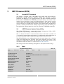
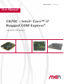
CB70C - Rugged COM Express® (VITA 59 RCE) with Intel® Core™ i7
CB70C - Rugged COM Express® (VITA 59 RCE) with Intel®
Core™ i7
The CB70C is a member of a new family of Rugged COM Express® modules
which is controlled by a third generation Intel® Core™ i7 processor running at up
to 3.1 GHz maximum turbo frequency bringing state-of-the-art PC technology onto
a small form factor. This means a scalable performance with 1 up to 4 cores,
integrated graphics, as well as support of Intel® AMT or Open CL 1.1.
The board can be controlled using a Board Management Controller and an adaptable
BIOS which ensures flexibility in tailoring the complete system for the final
application. Intel® AMT support is actively integrated in the BIOS adaptation.
The modules are 100% compatible to COM Express® modules of Pin-out Type 6.
They conform to the new VITA-59 standard which specifies the mechanics to make
COM Express® modules suitable for operation in harsh environments.
The modules are embedded in a covered frame ensuring EMC protection and
allowing efficient conductive cooling. Air cooling is also possible by applying a
heat sink on top of the cover.
The CB70C accommodates up to 16 GB of directly soldered main memory and
supports other memory like USB Flash on the carrier board.
The interfaces include a combination of PCI Express® links, LVDS, DDI, VGA,
high-definition audio, SATA, Ethernet and USB.
The CB70C is screened for operation from -40°C to +85°C (Tcase). Only soldered
components are used to withstand shock and vibration, and the design is optimized
for conformal coating.
For evaluation and development purposes a microATX carrier board is in
preparation.
MEN Mikro Elektronik GmbH
20CB70C00 E1 – 2014-06-18
2
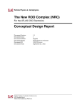
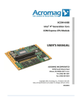
Diagram
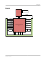
Diagram
DDR3 SDRAM
Intel® Core™
Processor
1 PEG x16
FDI
DMI
2 SATA (6 Gb)
3 DDI
2 SATA (3 Gb)
LVDS dual channel
4 USB 3.0
VGA
4 USB 2.0
Intel® Platform Controller Hub
QM77
HD Audio
7 PCIe x1 (2.x)
Speaker
Gigabit Ethernet PHY
BIOS TPM BMC
8 GPIO
SPI
LPC
SMBus
COM Express® Type 6 connectors A‐B & C‐D
MEN Mikro Elektronik GmbH
20CB70C00 E1 – 2014-06-18
3
Technical Data
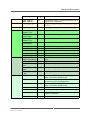
Technical Data
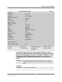
CPU
• Intel® Core™ i7-3612QE
- 2.1 GHz processor core frequency
- 3.1 GHz maximum turbo frequency
- 1066 MHz system bus frequency
• Chipset
- QM77 Platform Controller Hub (PCH)
Memory
• 6 MB last level cache integrated in i7 processor
• Up to 16 GB SDRAM system memory
- Soldered
- DDR3 with ECC support
- Up to 1066 MHz memory bus frequency
• 16 MB boot Flash
Serial ATA (SATA)
• Four ports via COM Express® connector
• Two ports with SATA Revision 2.x support
- Transfer rates up to 300 MB/s (3 Gbit/s)
• Two ports with SATA Revision 3.x support
- Transfer rates up to 600 MB/s (6 Gbit/s)
• RAID level 0/1/5/10 support
Graphics
•
•
•
•
•
Integrated in processor and chipset
Maximum resolution: 2560 x 1600 pixels
One x16 link (PCI Express® graphics)
One VGA
Three DDI ports
- For DP, HDMI, DVI, SDVO
• One LVDS dual channel
- Up to 48-bit RGB
• Available via COM Express® connector
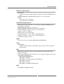
USB
• Four USB 3.0 host ports
- xHCI implementation
- Data rate up to 5 Gbit/s
• Four USB 2.0 host ports
- EHCI implementation
- Data rates up to 480 Mbit/s
• Available via COM Express® connector
MEN Mikro Elektronik GmbH
20CB70C00 E1 – 2014-06-18
4
Technical Data
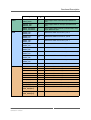
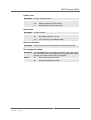
Ethernet
• One 10/100/1000Base-T Ethernet channel
• Three LED signals for LAN link, activity status and connection speed
• Available via COM Express® connector
PCI Express®
•
•
•
•
Seven x1 links
PCIe® 2.x support
Data rate up to 500 MB/s in each direction (5 Gbit/s per lane)
Available via COM Express® connector
GPIO
• 8 lines via COM Express® connector
HD Audio
• Via COM Express® connector
Board Management Controller
•
•
•
•
•
Input voltage supervision
Power sequencing
Board monitoring
Watchdog
Accessible via SMBus
Miscellaneous
•
•
•
•
•
Real-time clock (with supercapacitor or battery backup on the carrier board)
SMBus interface
LPC
SPI
Speaker
Rugged COM Express® Specifications
• In accordance with proposed standard VITA 59 RCE: Rugged COM Express® in
process
- With conduction cooling cover and frame
- Rugged COM Express® Basic, Module Pin-out Type 6
Electrical Specifications
• Supply voltage/power consumption:
- +12V (9 to 16 V), 48 W typ./ 70 W max.
- +5V (-5%/+5%) standby voltage, 1.1 W in standby operation
MEN Mikro Elektronik GmbH
20CB70C00 E1 – 2014-06-18
5
Technical Data
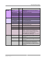
Mechanical Specifications
• Dimensions:
- 135 mm x 105 mm x 18 mm (height) (conforming to VITA 59 RCE Basic format)
• Rugged COM Express® PCB mounted between a cover and a frame
• Weight:
- 460 g (incl. cover and frame)
- 90 g (without cover and frame)
Environmental Specifications
• Temperature range (operation): -40..+85°C Tcase (Rugged COM Express®
cover/frame) (screened)
• Temperature range (storage): -40..+85°C
• Relative humidity (operation): max. 95% non-condensing
• Relative humidity (storage): max. 95% non-condensing
• Altitude: -300 m to +3000 m
• Shock: 50 m/s², 30 ms (EN 61373)
• Vibration (function): 1 m/s², 5 Hz – 150 Hz (EN 61373)
• Vibration (lifetime): 7.9 m/s², 5 Hz – 150 Hz (EN 61373)
• Conformal coating on request
MTBF
• 415 714 h @ 40°C according to IEC/TR 62380 (RDF 2000)
Safety
• Flammability
- PCB manufactured with a flammability rating of 94V-0 by UL recognized
manufacturers
EMC
• EMC behavior depends on the system and housing surrounding the COM
Express® module.
• The Rugged COM Express® module in its cover and frame supports the system
to meet the requirements of
- EN 55022 (radio disturbance)
- IEC 61000-4-2 (ESD)
- IEC 61000-4-3 (electromagnetic field immunity)
- IEC 61000-4-4 (burst)
- IEC 61000-4-5 (surge)
- IEC 61000-4-6 (conducted disturbances)
BIOS
• InsydeH2O™ UEFI Framework
MEN Mikro Elektronik GmbH
20CB70C00 E1 – 2014-06-18
6
Technical Data
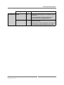
Intel® Active Management Technology
• Out of Band (OOB) Access
- Power off Access
- Independent of OS status
- Power status control
- Keyboard-Video-Mouse (KVM) Viewer (VNC-compatible)
- IDE-Redirect
- Serial-over-LAN
• Manageability Engine in Chipset
• Network Filters in Chipset
• Dedicated Flash Storage Area
Software Support
• Windows®
• Linux
For more information on supported operating system versions and
drivers, please see the online data sheet.
MEN Mikro Elektronik GmbH
20CB70C00 E1 – 2014-06-18
7
Configuration Options
Configuration Options
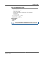
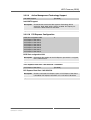
CPU
• Intel® Core™ i7-3615QE
- Quad Core, 2.3 GHz, 6 MB Cache, 45 W
• Intel® Core™ i7-3612QE
- Quad Core, 2.1 GHz, 6 MB Cache, 35 W
• Intel® Core™ i7-3555LE
- Dual Core, 2.5 GHz, 4 MB Cache, 25 W
• Intel® Core™ i7-3517UE
- Dual Core, 1.7 GHz, 4 MB Cache, 17 W
• Intel® Core™ i5-3610ME
- Dual Core, 2.7 GHz, 3 MB Cache, 35 W
• Intel® Core™ i3-3120ME
- Dual Core, 2.4 GHz, 3 MB Cache, 35 W
• Intel® Core™ i3-3217UE
- Dual Core, 1.6 GHz, 3 MB Cache, 17 W
• Intel® Celeron® 1020E
- Dual Core, 2.2 GHz, 2 MB Cache, 35 W
• Intel® Celeron® 1047UE
- Dual Core, 1.4 GHz, 2 MB Cache, 17 W
• Intel® Celeron® 927UE
- Single Core, 1.5 GHz, 1 MB Cache, 17 W
• Intel® Celeron® 827E
- Single Core, 1.4 GHz, 1.5 MB Cache, 17 W
Memory
• System RAM
- 2 GB, 4 GB, 8 GB or 16 GB
COM Express®
• Also available in accordance with PICMG COM.0 COM Express® Module Base
Specification
- Without conduction cooling wings, without cover and frame
• COM Express® Basic (135 mm x 105 mm), Module Pin-out Type 6
Cooling Concept
• Conduction-cooled versions according to VITA 59 RCE: Rugged COM
Express® in process
• Air-cooled versions according to PICMG COM.0 COM Express® standard
Please note that some of these options may only be available for large volumes.
Please ask our sales staff for more information.
For available standard configurations see the online data sheet.
MEN Mikro Elektronik GmbH
20CB70C00 E1 – 2014-06-18
8
Product Safety
Product Safety
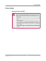
Electrostatic Discharge (ESD)
!
MEN Mikro Elektronik GmbH
20CB70C00 E1 – 2014-06-18
Computer boards and components contain electrostatic sensitive
devices. Electrostatic discharge (ESD) can damage components. To
protect the board and other components against damage from static
electricity, you should follow some precautions whenever you work on
your computer.
• Power down and unplug your computer system when working on the
inside.
• Hold components by the edges and try not to touch the IC chips,
leads, or circuitry.
• Use a grounded wrist strap before handling computer components.
• Place components on a grounded antistatic pad or on the bag that
came with the component whenever the components are separated
from the system.
• Only store the board in its original ESD-protected packaging. Retain
the original packaging in case you need to return the board to MEN
for repair.
9
About this Document
About this Document
This user manual is intended only for system developers and integrators, it is not
intended for end users.
It describes the hardware functions of the board, connection of peripheral devices
and integration into a system. It also provides additional information for special
applications and configurations of the board.
The manual does not include detailed information on individual components (data
sheets etc.). A list of literature is given in the appendix.
Product Naming
’CB70C’ is used throughout this document to name the products described.
However, descriptions are generally valid for the CB70 COM Express module, too.
Specific differences will be mentioned explicitly.
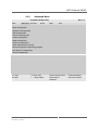
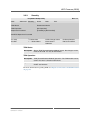
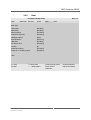
History
Issue
E1
MEN Mikro Elektronik GmbH
20CB70C00 E1 – 2014-06-18
Comments
First issue
Date
2014-06-18
10
About this Document
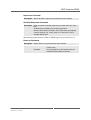
Conventions
!
Indicates important information or warnings concerning proper functionality of the product described in this document.
The globe icon indicates a hyperlink that links directly to the Internet,
where the latest updated information is available.
When no globe icon is present, the hyperlink links to specific elements
and information within this document.
italics
Folder, file and function names are printed in italics.
bold
Bold type is used for emphasis.
mono
A monospaced font type is used for hexadecimal numbers, listings, C
function descriptions or wherever appropriate. Hexadecimal numbers
are preceded by "0x".
comment
Comments embedded into coding examples are shown in green text.
IRQ#
/IRQ
Signal names followed by a hashtag "#" or preceded by a forward
slash "/" indicate that this signal is either active low or that it becomes
active at a falling edge.
in/out
Signal directions in signal mnemonics tables generally refer to the corresponding board or component, "in" meaning "to the board or component", "out" meaning "from it the board or component".
Blue vertical lines in the outer margin indicate sections where changes
have been made to this version of the document.
MEN Mikro Elektronik GmbH
20CB70C00 E1 – 2014-06-18
11
About this Document
Legal Information
Changes
MEN Mikro Elektronik GmbH ("MEN") reserves the right to make changes without further notice to any products
herein.
Warranty, Guarantee, Liability
MEN makes no warranty, representation or guarantee of any kind regarding the suitability of its products for any
particular purpose, nor does MEN assume any liability arising out of the application or use of any product or
circuit, and specifically disclaims any and all liability, including, without limitation, consequential or incidental
damages. TO THE EXTENT APPLICABLE, SPECIFICALLY EXCLUDED ARE ANY IMPLIED
WARRANTIES ARISING BY OPERATION OF LAW, CUSTOM OR USAGE, INCLUDING WITHOUT
LIMITATION, THE IMPLIED WARRANTIES OF MERCHANTABILITY AND FITNESS FOR A
PARTICULAR PURPOSE OR USE. In no event shall MEN be liable for more than the contract price for the
products in question. If buyer does not notify MEN in writing within the foregoing warranty period, MEN shall
have no liability or obligation to buyer hereunder.
The publication is provided on the terms and understanding that:
1. MEN is not responsible for the results of any actions taken on the basis of information in the publication, nor
for any error in or omission from the publication; and
2. MEN is not engaged in rendering technical or other advice or services.
MEN expressly disclaims all and any liability and responsibility to any person, whether a reader of the publication
or not, in respect of anything, and of the consequences of anything, done or omitted to be done by any such person
in reliance, whether wholly or partially, on the whole or any part of the contents of the publication.
Conditions for Use, Field of Application
The correct function of MEN products in mission-critical and life-critical applications is limited to the
environmental specification given for each product in the technical user manual. The correct function of MEN
products under extended environmental conditions is limited to the individual requirement specification and
subsequent validation documents for each product for the applicable use case and has to be agreed upon in writing
by MEN and the customer. Should the customer purchase or use MEN products for any unintended or
unauthorized application, the customer shall indemnify and hold MEN and its officers, employees, subsidiaries,
affiliates, and distributors harmless against all claims, costs, damages, and expenses, and reasonable attorney fees
arising out of, directly or indirectly, any claim or personal injury or death associated with such unintended or
unauthorized use, even if such claim alleges that MEN was negligent regarding the design or manufacture of the
part. In no case is MEN liable for the correct function of the technical installation where MEN products are a part
of.
Trademarks
All products or services mentioned in this publication are identified by the trademarks, service marks, or product
names as designated by the companies which market those products. The trademarks and registered trademarks
are held by the companies producing them. Inquiries concerning such trademarks should be made directly to those
companies.
Conformity
MEN products are no ready-made products for end users. They are tested according to the standards given in the
Technical Data and thus enable you to achieve certification of the product according to the standards applicable in
your field of application.
MEN Mikro Elektronik GmbH
20CB70C00 E1 – 2014-06-18
12
About this Document
RoHS
Since July 1, 2006 all MEN standard products comply with RoHS legislation.
Since January 2005 the SMD and manual soldering processes at MEN have already been completely lead-free.
Between June 2004 and June 30, 2006 MEN’s selected component suppliers have changed delivery to RoHScompliant parts. During this period any change and status was traceable through the MEN ERP system and the
boards gradually became RoHS-compliant.
WEEE Application
The WEEE directive does not apply to fixed industrial plants and tools. The compliance is the responsibility of the
company which puts the product on the market, as defined in the directive; components and sub-assemblies are
not subject to product compliance.
In other words: Since MEN does not deliver ready-made products to end users, the WEEE directive is not
applicable for MEN. Users are nevertheless recommended to properly recycle all electronic boards which have
passed their life cycle.
Nevertheless, MEN is registered as a manufacturer in Germany. The registration number can be provided on
request.
Copyright © 2014 MEN Mikro Elektronik GmbH. All rights reserved.
Germany
MEN Mikro Elektronik GmbH
Neuwieder Straße 3-7
90411 Nuremberg
Phone +49-911-99 33 5-0
Fax +49-911-99 33 5-901
E-mail [email protected]
www.men.de
MEN Mikro Elektronik GmbH
20CB70C00 E1 – 2014-06-18
France
MEN Mikro Elektronik SAS
18, rue René Cassin
ZA de la Châtelaine
74240 Gaillard
Phone +33 (0) 450-955-312
Fax +33 (0) 450-955-211
E-mail [email protected]
www.men-france.fr
USA
MEN Micro Inc.
860 Penllyn Blue Bell Pike
Blue Bell, PA 19422
Phone (215) 542-9575
Fax (215) 542-9577
E-mail [email protected]
www.menmicro.com
13
Contents
Contents
1 Getting Started . . . . . . . . . . . . . . . . . . . . . . . . . . . . . . . . . . . . . . . . . . . . . . . .
1.1 Map of the Board. . . . . . . . . . . . . . . . . . . . . . . . . . . . . . . . . . . . . . . . .
1.1.1
CB70C Rugged COM Express . . . . . . . . . . . . . . . . . . . . . . .
1.1.2
CB70 COM Express . . . . . . . . . . . . . . . . . . . . . . . . . . . . . . .
1.2 First Operation. . . . . . . . . . . . . . . . . . . . . . . . . . . . . . . . . . . . . . . . . . .
1.3 Configuring BIOS . . . . . . . . . . . . . . . . . . . . . . . . . . . . . . . . . . . . . . . .
1.4 Installing Operating System Software. . . . . . . . . . . . . . . . . . . . . . . . .
1.5 Installing Driver Software . . . . . . . . . . . . . . . . . . . . . . . . . . . . . . . . . .
18
18
18
19
20
20
20
20
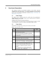
2 Functional Description . . . . . . . . . . . . . . . . . . . . . . . . . . . . . . . . . . . . . . . . . .
2.1 Power Supply. . . . . . . . . . . . . . . . . . . . . . . . . . . . . . . . . . . . . . . . . . . .
2.2 Power States . . . . . . . . . . . . . . . . . . . . . . . . . . . . . . . . . . . . . . . . . . . .
2.3 Board Management Controller . . . . . . . . . . . . . . . . . . . . . . . . . . . . . .
2.4 Status LED. . . . . . . . . . . . . . . . . . . . . . . . . . . . . . . . . . . . . . . . . . . . . .
2.5 Reset . . . . . . . . . . . . . . . . . . . . . . . . . . . . . . . . . . . . . . . . . . . . . . . . . .
2.6 Real-Time Clock . . . . . . . . . . . . . . . . . . . . . . . . . . . . . . . . . . . . . . . . .
2.7 Processor Core. . . . . . . . . . . . . . . . . . . . . . . . . . . . . . . . . . . . . . . . . . .
2.7.1
Thermal Considerations . . . . . . . . . . . . . . . . . . . . . . . . . . . .
2.8 Intel Active Management Technology (AMT) . . . . . . . . . . . . . . . . . .
2.9 Trusted Platform Module. . . . . . . . . . . . . . . . . . . . . . . . . . . . . . . . . . .
2.10 Memory and Mass Storage . . . . . . . . . . . . . . . . . . . . . . . . . . . . . . . . .
2.10.1 DRAM System Memory . . . . . . . . . . . . . . . . . . . . . . . . . . . .
2.10.2 Boot Flash . . . . . . . . . . . . . . . . . . . . . . . . . . . . . . . . . . . . . . .
2.11 Mass Storage . . . . . . . . . . . . . . . . . . . . . . . . . . . . . . . . . . . . . . . . . . . .
2.11.1 Serial ATA (SATA) . . . . . . . . . . . . . . . . . . . . . . . . . . . . . . . .
2.12 Graphics. . . . . . . . . . . . . . . . . . . . . . . . . . . . . . . . . . . . . . . . . . . . . . . .
2.12.1 Display Configuration . . . . . . . . . . . . . . . . . . . . . . . . . . . . . .
2.12.2 Digital Display Interface . . . . . . . . . . . . . . . . . . . . . . . . . . . .
2.12.3 LVDS. . . . . . . . . . . . . . . . . . . . . . . . . . . . . . . . . . . . . . . . . . .
2.12.4 VGA . . . . . . . . . . . . . . . . . . . . . . . . . . . . . . . . . . . . . . . . . . .
2.13 USB . . . . . . . . . . . . . . . . . . . . . . . . . . . . . . . . . . . . . . . . . . . . . . . . . . .
2.14 Ethernet Interface . . . . . . . . . . . . . . . . . . . . . . . . . . . . . . . . . . . . . . . .
2.14.1 Ethernet Status LEDs . . . . . . . . . . . . . . . . . . . . . . . . . . . . . .
2.15 Audio . . . . . . . . . . . . . . . . . . . . . . . . . . . . . . . . . . . . . . . . . . . . . . . . . .
2.16 Speaker Interface . . . . . . . . . . . . . . . . . . . . . . . . . . . . . . . . . . . . . . . . .
2.17 PCI Express . . . . . . . . . . . . . . . . . . . . . . . . . . . . . . . . . . . . . . . . . . . . .
2.18 Express Card Interface (Optional). . . . . . . . . . . . . . . . . . . . . . . . . . . .
2.19 General Purpose Inputs (Optional) . . . . . . . . . . . . . . . . . . . . . . . . . . .
2.20 General Purpose Outputs . . . . . . . . . . . . . . . . . . . . . . . . . . . . . . . . . . .
2.21 SMBus . . . . . . . . . . . . . . . . . . . . . . . . . . . . . . . . . . . . . . . . . . . . . . . . .
2.22 LPC Bus. . . . . . . . . . . . . . . . . . . . . . . . . . . . . . . . . . . . . . . . . . . . . . . .
2.23 SPI Interface . . . . . . . . . . . . . . . . . . . . . . . . . . . . . . . . . . . . . . . . . . . .
21
21
21
22
24
24
25
25
26
27
27
27
27
27
27
27
28
28
28
29
29
29
30
30
31
31
31
31
32
33
34
34
35
MEN Mikro Elektronik GmbH
20CB70C00 E1 – 2014-06-18
14
Contents
2.24 Rugged COM Express (VITA 59) . . . . . . . . . . . . . . . . . . . . . . . . . . . .
2.24.1 Module Form Factors . . . . . . . . . . . . . . . . . . . . . . . . . . . . . .
2.24.2 Thermal Concept. . . . . . . . . . . . . . . . . . . . . . . . . . . . . . . . . .
2.24.3 COM Express Connectors. . . . . . . . . . . . . . . . . . . . . . . . . . .
36
36
36
38
3 UEFI Firmware (BIOS) . . . . . . . . . . . . . . . . . . . . . . . . . . . . . . . . . . . . . . . . .
3.1 InsydeH2O Framework . . . . . . . . . . . . . . . . . . . . . . . . . . . . . . . . . . . .
3.2 UEFI Firmware System Setup Utility . . . . . . . . . . . . . . . . . . . . . . . . .
3.2.1
Main . . . . . . . . . . . . . . . . . . . . . . . . . . . . . . . . . . . . . . . . . . .
3.2.2
Advanced Menu . . . . . . . . . . . . . . . . . . . . . . . . . . . . . . . . . .
3.2.3
Security . . . . . . . . . . . . . . . . . . . . . . . . . . . . . . . . . . . . . . . . .
3.2.4
Power. . . . . . . . . . . . . . . . . . . . . . . . . . . . . . . . . . . . . . . . . . .
3.2.5
Boot . . . . . . . . . . . . . . . . . . . . . . . . . . . . . . . . . . . . . . . . . . . .
3.2.6
Exit . . . . . . . . . . . . . . . . . . . . . . . . . . . . . . . . . . . . . . . . . . . .
47
47
47
47
50
63
65
67
71
4 Appendix . . . . . . . . . . . . . . . . . . . . . . . . . . . . . . . . . . . . . . . . . . . . . . . . . . . . .
4.1 Literature and Web Resources . . . . . . . . . . . . . . . . . . . . . . . . . . . . . . .
4.1.1
COM Express . . . . . . . . . . . . . . . . . . . . . . . . . . . . . . . . . . . .
4.1.2
Rugged COM Express . . . . . . . . . . . . . . . . . . . . . . . . . . . . .
4.1.3
CPU . . . . . . . . . . . . . . . . . . . . . . . . . . . . . . . . . . . . . . . . . . . .
4.1.4
Ethernet . . . . . . . . . . . . . . . . . . . . . . . . . . . . . . . . . . . . . . . . .
4.1.5
HD Audio . . . . . . . . . . . . . . . . . . . . . . . . . . . . . . . . . . . . . . .
4.1.6
PCI Express. . . . . . . . . . . . . . . . . . . . . . . . . . . . . . . . . . . . . .
4.1.7
SATA . . . . . . . . . . . . . . . . . . . . . . . . . . . . . . . . . . . . . . . . . . .
4.1.8
USB . . . . . . . . . . . . . . . . . . . . . . . . . . . . . . . . . . . . . . . . . . . .
4.2 Finding out the Product’s Article Number, Revision and
Serial Number . . . . . . . . . . . . . . . . . . . . . . . . . . . . . . . . . . . . . . . . . . .
73
73
73
73
73
73
74
74
74
74
MEN Mikro Elektronik GmbH
20CB70C00 E1 – 2014-06-18
74
15
Figures
Figure 1.
Figure 2.
Figure 3.
Figure 4.
MEN Mikro Elektronik GmbH
20CB70C00 E1 – 2014-06-18
Map of the board (CB70C Rugged COM Express) . . . . . . . . . . . . . . .
Map of the board (CB70 COM Express) . . . . . . . . . . . . . . . . . . . . . . .
RCE thermal concept: cooling wings between frame and cover . . . . .
Labels giving the product’s article number, revision and
serial number . . . . . . . . . . . . . . . . . . . . . . . . . . . . . . . . . . . . . . . . . . . .
18
19
37
74
16
Tables
Table 1.
Table 2.
Table 3.
Table 4.
Table 5.
Table 6.
Table 7.
Table 8.
Table 9.
MEN Mikro Elektronik GmbH
20CB70C00 E1 – 2014-06-18
Supported power states. . . . . . . . . . . . . . . . . . . . . . . . . . . . . . . . . . . . .
Error codes signaled by board management controller via
LED flashes . . . . . . . . . . . . . . . . . . . . . . . . . . . . . . . . . . . . . . . . . . . . .
Processor core options on CB70C . . . . . . . . . . . . . . . . . . . . . . . . . . . .
Digital Display Interfaces. . . . . . . . . . . . . . . . . . . . . . . . . . . . . . . . . . .
Ethernet status LED modes . . . . . . . . . . . . . . . . . . . . . . . . . . . . . . . . .
GPIO usage. . . . . . . . . . . . . . . . . . . . . . . . . . . . . . . . . . . . . . . . . . . . . .
SMBus address map. . . . . . . . . . . . . . . . . . . . . . . . . . . . . . . . . . . . . . .
Pin assignment of COM Express connectors J1 and J2 . . . . . . . . . . . .
Signal Mnemonics . . . . . . . . . . . . . . . . . . . . . . . . . . . . . . . . . . . . . . . .
21
24
25
28
30
33
34
38
41
17
Getting Started
1
Getting Started
This chapter gives an overview of the board and some hints for first operation.
1.1
Map of the Board
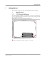
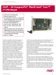
1.1.1
CB70C Rugged COM Express
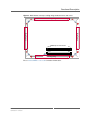
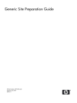
The following board map shows the board inside the cover and frame from its
connector side (bottom). The cover includes holes for mounting the Rugged COM
Express module onto a carrier.
Figure 1. Map of the board (CB70C Rugged COM Express)
Cooling Wing
Cooling Wing
Cooling Wing
COM Express Connectors
D110
D1
C110
B110
C1
B1
A110
A1
Cooling Wing
COM Express screw holes for installation on the carrier board
Screws connecting the frame and cover of the module . Do not remove.
MEN Mikro Elektronik GmbH
20CB70C00 E1 – 2014-06-18
18
Getting Started
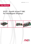
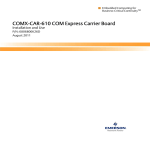
1.1.2
CB70 COM Express
The following board map shows the board from its connector side (bottom)
including the holes for mounting the Rugged COM Express module onto a carrier.
Figure 2. Map of the board (CB70 COM Express)
D110
D1
C110
B110
C1
B1
A110
A1
COM Express screw holes for installation on the carrier board
MEN Mikro Elektronik GmbH
20CB70C00 E1 – 2014-06-18
19
Getting Started
1.2
First Operation
You can use the following check list when installing the board for the first time and
with minimum configuration using a Windows host PC.
Power-down the system.
Plug the CB70C on your carrier board, making sure that the COM Express connectors are properly aligned.
Fasten the five screws connecting the COM Express module to the carrier
(marked in blue in Figure 1, Map of the board (CB70C Rugged COM Express)
on page 18 and Figure 2, Map of the board (CB70 COM Express) on page 19).
Connect a USB keyboard and mouse to the USB connectors of the carrier
board.
Connect a flat-panel display to the DVI connector of the carrier board.
Power-up the system.
You can start up the BIOS setup menu by hitting the <F2> key (see Chapter 3
UEFI Firmware (BIOS) on page 47).
Now you can make configurations in BIOS (see Chapter 3 UEFI Firmware
(BIOS) on page 47).
Observe the installation instructions for the respective software.
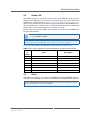
1.3
Configuring BIOS
The CB70C is equipped with an InsydeH2O UEFI framework. Normally you won’t
need to make any changes in the BIOS setup. If you do, however, you find further
details on the CB70C’s BIOS in Chapter 3 UEFI Firmware (BIOS) on page 47.
1.4
Installing Operating System Software
The board supports Windows and Linux.
!
By default, no operating system is installed on the board. Please refer to
the respective manufacturer's documentation on how to install operating
system software!
You can find any software available on the CB70C pages on MEN’s
website.
1.5
Installing Driver Software
For a detailed description on how to install driver software please refer to the
respective documentation.
You can find any driver software available for download on the CB70C
pages on MEN’s website.
MEN Mikro Elektronik GmbH
20CB70C00 E1 – 2014-06-18
20
Functional Description
2
Functional Description
The following describes the individual functions of the board and their
configuration on the board. There is no detailed description of the individual
controller chips and the CPU. They can be obtained from the data sheets or data
books of the semiconductor manufacturer concerned (Chapter 4.1 Literature and
Web Resources on page 73).
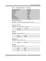
2.1
Power Supply
The CB70C board is supplied with +12V (9..16V) only. It can optionally be
supplied with +5V (±5%) standby voltage for the standby function in compliance
with the COM Express standard.
All other required voltages are generated onboard.
The CB70C supports the PWR_OK signal (input from main power supply) available
at the COM Express connector according to the PICMG COM.0 standard.
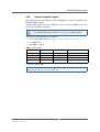
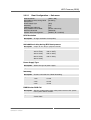
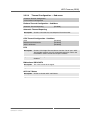
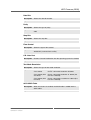
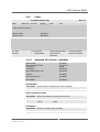
2.2
Power States
The CB70C board supports the system power states S0, S3, S4 and S5.
Table 1. Supported power states
State
Supported by
CB70C
S0
Working
yes
S1
All the processor caches are flushed, and the CPU(s)
stops executing instructions.
The power to the CPU(s) and RAM is maintained.
Devices that do not indicate they must remain on may
be powered off.
no
S2
CPU powered off. Cache is flushed to RAM.
no
S3
Commonly referred to as Standby, Sleep, or Suspend
to RAM (STR). RAM remains powered.
yes
S4
Hibernation or Suspend to Disk.
All content of main memory is saved to non-volatile
memory such as a hard drive, and is powered down.
yes
S5
Soft Off: G2/S5 is almost the same as G3 Mechanical
Off, except that the PSU still supplies power, at a
minimum, to the power button to allow return to S0.
A full reboot is required. No previous content is
retained.
Other components may remain powered so the
computer can "wake" on input from the keyboard,
clock, modem, LAN, or USB device.
yes
MEN Mikro Elektronik GmbH
20CB70C00 E1 – 2014-06-18
Description
21
Functional Description
2.3
Board Management Controller
The CB70C provides an intelligent board management controller (BMC) with the
following main features:
•
•
•
•
•
•
Supervision of power sequences
Supervision of board supply voltages and power good signals
Supervision of CPU overtemperature signal
Board status signaling
Watchdog functionality
SMBus communication
MEN provides a dedicated software driver for the board controller. For a detailed
description of the functionality of the driver software please refer to the drivers’
documentation.
You can find any driver software and documentation available for
download on the CB70C pages on MEN’s website.
Input Supply Voltage Monitoring
The BMC monitors the input supply voltage. The nominal input supply voltage is
+12V with a range from 9V up to 16V.
The state of the monitored voltage is provided to the BMC via a power good signal.
The BMC delays the power-up sequence until the input supply voltage is within
limits. If the high or low voltage limit is exceeded while the system is not in S5 or
S4 state, the BMC shuts down the CB70C for at least 4 seconds and signals a power
failure via the LEDs.
When the input voltage returns to the normal range, the BMC restarts the board.
RTC Supply Voltage Monitoring
The BMC measures at power-up time and once every hour whether the supply
voltage for the real-time clock provided by the COM.0 carrier is in the correct
range. Measurement is done while the system is in S0 state only, with all voltages
stable. If the RTC voltage is too low, a power failure is signaled to the BMC.
External Watchdog
The watchdog device monitors the board on operating system level. If enabled, the
watchdog must be triggered by application software. If the trigger is overdue, the
watchdog initiates a board reset and this way can put the system back into operation
when the software hangs.
The watchdog uses a configurable time interval or is disabled. Settings are made
through BIOS or via an MEN software driver.
MEN Mikro Elektronik GmbH
20CB70C00 E1 – 2014-06-18
22
Functional Description
COM.0 power supply status signals
The board controller generates a shutdown signal to the platform controller hub if
there is an external power supply failure event (via the PWR_OK pin at the COM
Express connectors). At system start the signal is used to control the power
sequencing start.
Failure Management
The board controller detects and solves error conditions. When the system is
running into an error condition, the board controller tries to recover the system using
a range of different measures ranging from simply switching off power to a
complete reset of the configuration.
Failure Shutdown
In case of a power failure or if the error condition cannot be cleared, the board
controller tries to restart the system.
Reset Reason Register
The board controller provides a reset reason register, which can be read using
MEN’s software and holds as much information as possible about the reason of the
last reset.
Operating Hour Counter
The board controller provides an operating hour counter, which counts the time the
system is in S0 state and which can be queried by MEN’s software.
Power Cycle Counter
The board controller provides a power cycle counter, which counts the number of
times the system has been powered-up and which can be queried by MEN’s
software.
Over Temperature Signal
The over temperature signal of the CPU is monitored by the board controller.
Power Resume
The board controller starts the Power-up Sequence or stays off at power resume
after power loss depending on the "Power Resume Mode" setting in the BIOS.
See Chapter 3 UEFI Firmware (BIOS) on page 47.
MEN Mikro Elektronik GmbH
20CB70C00 E1 – 2014-06-18
23
Functional Description
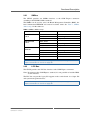
2.4
Status LED
The CB70C provides a user-defined signal for the status LED. By using the signal
GPO0 on the COM Express connector J1, board status messages can be shown with
a LED on the carrier board. See Chapter 2.20 General Purpose Outputs on page 33.
This signal is controlled by the board management controller. When the BIOS starts,
the carrier LED can be switched on. It is switched off when the board is switched off
and it flashes slowly when the board is in stand-by (S3) status.
During normal operation the LED can be switched on and off using the MEN driver
for the board controller.
You can find any driver software available for download on the CB70C
pages on MEN’s website.
For the exact position of the signal on the COM Express J1 connector see Table
8, Pin assignment of COM Express connectors J1 and J2 on page 38.
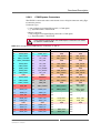
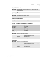
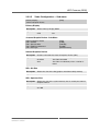
In case of a board failure, the LED displays the following error messages:
Table 2. Error codes signaled by board management controller via LED flashes
Number
of
Flashes
Error
Description
0
CPUBCI_ERR_NONE
No error
1
CPUBCI_ERR_33V
3.3 V failure
2
CPUBCI_ERR_INP
Input voltage failure
3
CPUBCI_ERR_NO_EXT_PWR_OK
External power supply failure
4
CPUBCI_ERR_CPU_TOO_HOT
CPU temperature too high
5
CPUBCI_ERR_BIOS_TIMEOUT
BIOS startup failure
>5
2.5
Internal error
Reset
The CB70C provides the reset signals CB_RESET# and SYS_RESET# which are
available at the COM Express connector according to the PICMG COM.0 standard.
You can find the pinout for the reset signals in Table 8, Pin assignment of COM
Express connectors J1 and J2 on page 38.
MEN Mikro Elektronik GmbH
20CB70C00 E1 – 2014-06-18
24
Functional Description
2.6
Real-Time Clock
The board includes a real-time clock connected to the processor as a system RTC.
The RTC has an accuracy of approximately 1.7 seconds/day (11 minutes/year) at
25°C.
The real-time clock device is connected to the CPU via SMBus. Due to its reduced
current consumption, the life time of the battery or supercapacitor installed on the
carrier can be increased considerably compared to the CPU internal RTC.
MEN provides a dedicated software driver for the RTC device in order to
set date and time as usual in Windows. For a detailed description of the
functionality of the driver and for downloading the software please refer
to the drivers' documentation on MEN’s website.
The real-time clock should be buffered by a supply voltage from the carrier board.
The supply voltage can be provided by an external supercapacitor or battery device
mounted on the carrier.
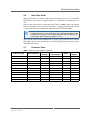
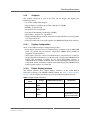
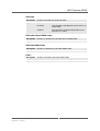
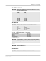
2.7
Processor Core
Table 3. Processor core options on CB70C
Processor Type
Core Frequency
Cores/
Threads
Power
Consumption
Cache
AMT
Support
Core i7-3615QE
2.3 GHz
4/8
45 W
6 MB
yes
Core i7-3612QE
2.1 GHz
4/8
35 W
6 MB
yes
Core i7-3555LE
2.5 GHz
2/4
25 W
4 MB
yes
Core i7-3517UE
1.7 GHz
2/4
17 W
4 MB
yes
Core i5-3610ME
2.7 GHz
2/4
35 W
3 MB
yes
Core i3-3120ME
2.4 GHz
2/4
35 W
3 MB
no
Core i3-3217UE
1.6 GHz
2/4
17 W
3 MB
no
Celeron 1020E
2.2 GHz
2/2
35 W
2 MB
no
Celeron 1047UE
1.4 GHz
2/2
17 W
2 MB
no
Celeron 927UE
1.5 GHz
1/1
17 W
1 MB
no
Celeron 827E
1.4 GHz
1/1
17 W
1.5 MB
no
MEN Mikro Elektronik GmbH
20CB70C00 E1 – 2014-06-18
25
Functional Description
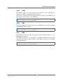
2.7.1
Thermal Considerations
The CB70C has a power dissipation of up to 45 W.
The Rugged COM Express module is enclosed inside a cover and frame and
therefore provides a flexible thermal interface that can be used as needed to fulfill
the thermal needs of the application. Typically you should use it for conduction
cooling or convection cooling. It depends on the system configuration and airflow if
an additional heat sink is needed or not. In any case you should check your thermal
conditions and implement appropriate cooling.
See also Chapter 2.24.2 Thermal Concept on page 36.
!
MEN Mikro Elektronik GmbH
20CB70C00 E1 – 2014-06-18
Please note that if you do not use the cover and frame supplied by MEN
and/or no heat sink, warranty on functionality and reliability of the
CB70C may cease. If you have any questions or problems regarding
thermal behavior, please contact MEN.
26
Functional Description
2.8
Intel Active Management Technology (AMT)
CB70C boards equipped with an Intel Core i7 or i5 processor support Intel Active
Management Technology (AMT 8.0). Intel AMT is powered by a separate hardware
engine in Intel chipsets which enables e.g. out-of-band (OOB) diagnostics, remote
control, IDE-Redirect, Serial-over-LAN (SOL), agent presence checking and
network traffic filtering.
For information on how to enable the AMT BIOS extension see Chapter 3 UEFI
Firmware (BIOS).
MEN provides an application note on how to switch on the AMT
functionality and log onto the CPU board via VNC afterwards. See
MEN’s website.
!
2.9
If the supercapacitor and/or the battery is empty, the CB70C loses its
complete AMT settings due to Intel’s security standards.
Trusted Platform Module
A trusted platform module to protect the content of the SATA storage devices is
implemented on the CB70C. The module is compliant to the TPM v1.2
specification.
2.10
Memory and Mass Storage
2.10.1
DRAM System Memory
The board provides up to 16 GB onboard, soldered DDR3 (double data rate)
SDRAM. The memory bus is 2x72 bits wide (dual channel) and operates with up to
1066 MHz.
2.10.2
Boot Flash
The CB70C has an 64-Mbit SPI Serial Flash implemented as onboard Flash for
BIOS data and the AMT firmware. It supports Flash devices with up to 16 MB.
2.11
Mass Storage
2.11.1
Serial ATA (SATA)
The CB70C provides four SATA ports at the COM Express connector.
Two interfaces are compliant with SATA Revision 2.x and support transfer rates of
3.0 Gbit/s; two interfaces are compliant with SATA Revision 2.x and support
transfer rates of 6.0 Gbit/s.
The interfaces support AHCI and RAID mode.
You can find the pinout for the SATA signals in Table 8, Pin assignment of COM
Express connectors J1 and J2 on page 38.
MEN Mikro Elektronik GmbH
20CB70C00 E1 – 2014-06-18
27
Functional Description
2.12
Graphics
The graphics subsystem is part of the CPU and the chipset and supports the
following features:
•
•
•
•
•
•
•
Up to three independent displays
Digital display resolutions up to 2560 x 1600 pixels @ 60Hz
HDMI 1.4a specification
DisplayPort 1.1a specification
Dynamic Video Memory Technology (DVMT)
DirectX® 11, OpenCL 1.1, OpenGL 3.1
High-bandwidth Digital Content Protection for high definition content playback
over digital interfaces
• Integrated audio codecs for audio support over HDMI and DisplayPort interfaces
2.12.1
Display Configuration
There are two different display configurations possible:
• If two display interfaces are used simultaneously, resolutions of up to 2560x1600
pixels are possible for each interface. DisplayPort, HDMI, DVI or LVDS are
supported on both interfaces.
• Three display interfaces can be used simultaneously if two interfaces are fixed as
DisplayPort. The third interface can then be used as DisplayPort, HDMI, DVI or
LVDS. The maximum resolution of one fixed DisplayPort interface is
2560x1600, the maximum resolution of the second fixed DisplayPort interface is
1920x1200 and the maximum resolution of the third DisplayPort, HDMI, DVI or
LVDS capable interface is 1920x1200.
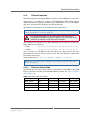
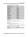
2.12.2
Digital Display Interface
The CB70C provides three Digital Display Interfaces at the COM Express
connector according to the PICMG COM.0 standard. See Table 4, Digital Display
Interfaces for the supported interface types and maximum resolutions per port.
Table 4. Digital Display Interfaces
Digital Display
Port#
Supported Interfaces
Resolution
B
COM.0 R2.0
DDI1
DP, HDMI, DVI, SDVO
1920x1200 60 Hz
C
COM.0 R2.0
DDI2
DP, HDMI, DVI
2560x1600 60 Hz
D
COM.0 R2.0
DDI3
DP, HDMI, DVI
2560x1600 60 Hz/
1920x1200 in a three
display configuration
MEN Mikro Elektronik GmbH
20CB70C00 E1 – 2014-06-18
Usage
28
Functional Description
2.12.3
LVDS
The CB70C supports one dual channel LVDS interface at the COM Express
connector according to the PICMG COM.0 standard.
The interface can be operated in single channel mode with up to 24-bit RGB data or
dual channel mode with up to 48-bit RGB data.
You can find the pinout for the LVDS signals in Table 8, Pin assignment of COM
Express connectors J1 and J2 on page 38.
2.12.4
VGA
The CB70C supports one VGA interface at the COM Express connector according
to the PICMG COM.0 standard.
You can find the pinout for the VGA signals in Table 8, Pin assignment of COM
Express connectors J1 and J2 on page 38.
2.13
USB
The CB70C provides four USB 3.0 interfaces and four USB 2.0 interfaces at the
COM Express connector.
The USB 2.0 interfaces are controlled by an EHCI controller in the platform
controller hub which also supports USB 1.1. The USB 3.0 interfaces are controlled
by an xHCI controller.
You can find the pinout for the USB signals in Table 8, Pin assignment of COM
Express connectors J1 and J2 on page 38.
MEN Mikro Elektronik GmbH
20CB70C00 E1 – 2014-06-18
29
Functional Description
2.14
Ethernet Interface
The CB70C provides one Gigabit Ethernet interface at the COM Express connector.
The interface is controlled by an Intel 82579LM Ethernet PHY which supports
AMT functionality. It supports 10 Mbits/s up to 1000 Mbits/s as well as full-duplex
operation, autonegotiation and Wake-on-LAN functionality.
The Ethernet transformer has to be mounted on the carrier board.
You can find the pinout for the Ethernet signals in Table 8, Pin assignment of COM
Express connectors J1 and J2 on page 38.
The unique MAC address is set at the factory and should not be
changed. Any attempt to change this address may create node or bus
contention and thereby render the board inoperable.
!
The naming of the interfaces may differ depending on the operating system. The
MAC addresses on CB70C are:
0x 00 C0 3A C5 A0 00 - 0x 00 C0 3A C5 AF FF
• CB70:
• CB70C:
0x 00 C0 3A C5 B0 00 - 0x 00 C0 3A C5 BF FF
where "00 C0 3A" is the MEN vendor code. The last six digits describe the range
from which the addresses for the board are taken. The serial number is added to the
first number in the range:
Serial number 0042: 0x A0 xx = 0xA000 + 0x002A = 0x A0 2A.
See Chapter 4.2 Finding out the Product’s Article Number, Revision and Serial
Number on page 74.
2.14.1
Ethernet Status LEDs
The CB70C provides four control signals for the Ethernet status LEDs at the COM
Express connector according to the PICMG COM.0 standard. See Table 5, Ethernet
status LED modes.
Table 5. Ethernet status LED modes
Signal
On
Off
Blinking
GBE0_ACT#
ACT
Tx/Rx activity No activity
Tx/Rx activity
GBE0_LINK1000#
LINK 1000
Link Up 1000 No link
n/a
GBE0_LINK100#
LINK 100
Link Up 100
No link
n/a
GBE0_LINK#
LINK
LinkUp
No link
n/a
MEN Mikro Elektronik GmbH
20CB70C00 E1 – 2014-06-18
Mode
30
Functional Description
2.15
Audio
The CB70C supports one high definition audio interface at the COM Express
connector according to the PICMG COM.0 standard. Three HD Audio devices can
be connected to the interface.
You can find the pinout for the audio signals in Table 8, Pin assignment of COM
Express connectors J1 and J2 on page 38.
2.16
Speaker Interface
The CB70C support one speaker interface at the COM Express connector according
to the PICMG COM.0 standard.
You can find the pinout for the speaker signal in Table 8, Pin assignment of COM
Express connectors J1 and J2 on page 38.
2.17
PCI Express
According to the COM Express standard, the CB70C supports 7 PCI Express x1
lanes and 1 PEG x16 interface on the COM Express connectors.
The board also supports lane grouping of the PCI Express ports according to the
COM.0 standard.
The ports support the PCIe 2.x standard; i.e. data rates up to 500 MB/s in each
direction (5 Gbit/s per lane).
You can find the pinout for the PCI Express signals in Table 8, Pin assignment of
COM Express connectors J1 and J2 on page 38.
2.18
Express Card Interface (Optional)
As an option, the CB70C provides two Express Card interfaces at the COM Express
connector according to the PICMG COM.0 standard. Each interface consists of the
EXCDx_PERST# and the EXCDx_CPPE# signal.
By default, the signals are deactivated on the CB70C. On request, MEN can
implement a BIOS item for activating the interfaces.
Please contact MEN’s sales team for further information.
You can find the pinout for the Express card signals in Table 8, Pin assignment of
COM Express connectors J1 and J2 on page 38.
MEN Mikro Elektronik GmbH
20CB70C00 E1 – 2014-06-18
31
Functional Description
2.19
General Purpose Inputs (Optional)
As an option, the CB70C provides four GPI pins at the COM Express connector
according to the PICMG COM.0 standard.
The GPIs are not supported by MEN’s software drivers. On request, MEN can
implement support for these signals.
Please contact MEN’s sales team for further information
You can find the pinout for the GPI in Table 8, Pin assignment of COM Express
connectors J1 and J2 on page 38.
MEN Mikro Elektronik GmbH
20CB70C00 E1 – 2014-06-18
32
Functional Description
2.20
General Purpose Outputs
The CB70C provides four GPO pins at the COM Express connector according to the
PICMG COM.0 standard.
The four GPO outputs are used as LEDs and can be accessed via MEN’s driver for
the board management controller.
For available downloads see the CB70C pages on MEN’s website.
The following LED functions are available:
• 1 board status LED (yellow, see Chapter 2.4 Status LED on page 24)
• 1 user LED (blue)
• 2 user LEDs (yellow)
Table 6. GPIO usage
COM.0 GPIO
1
PCH1 GPIO
BC GPIO
Function
GPO0
GPIO36
BRD_STAT_LED
Board Status Indicator
GPO1
GPIO37
HOT_LED_R
User-defined
GPO2
GPIO16
BC_LED[2]
User-defined
GPO3
GPIO49
BC_LED[3]
User-defined
Platform Controller Hub
You can find the pinout for the GPO signals in Table 8, Pin assignment of COM
Express connectors J1 and J2 on page 38.
MEN Mikro Elektronik GmbH
20CB70C00 E1 – 2014-06-18
33
Functional Description
2.21
SMBus
The CB70C provides one SMBus interface at the COM Express connector
according to the PICMG COM.0 standard.
The SMBus can be used to access the Board Management Controller (BMC), the
board information EEPROM and external real-time clock. See Table 7, SMBus
address map. for the addresses.
Table 7. SMBus address map.
Device
SPD EEPROM
CHA-A
SPD EEPROM
CHA-B
Board Info
EEPROM
Address
Function
0xA1 / 0xA0
0x61/0x60
Protect Register
0x31/0x30
Temp. Sensor A
0xA5 / 0xA4
0x65/0x64
Protect Register
0x35/0x34
Temp. Sensor B
0xAF / 0xAE
0x6F/0x6E
Protect Register
0x3F/0x3E
Temp. Sensor Board
BC
0x9B/0x9A
External RTC
0xA3/0xA2
You can find the pinout for the SMBus signals in Table 8, Pin assignment of COM
Express connectors J1 and J2 on page 38.
2.22
LPC Bus
The CB70C provides one LPC bus interface at the COM Express connector.
Note: In contrast to the COM Express standard, it is not possible to load the BIOS
via this interface.
The LPC bus can provide legacy I/O support on the carrier board via a Super I/O
and system management devices.
You can find the pinout for the LPC bus signals in Table 8, Pin assignment of COM
Express connectors J1 and J2 on page 38.
MEN Mikro Elektronik GmbH
20CB70C00 E1 – 2014-06-18
34
Functional Description
2.23
SPI Interface
The CB70C provides one SPI interface at the COM Express connector.
Note: In contrast to the COM Express standard, it is not possible to load the BIOS
via this interface.
You can find the pinout for the SPI bus signals in Table 8, Pin assignment of COM
Express connectors J1 and J2 on page 38.
MEN Mikro Elektronik GmbH
20CB70C00 E1 – 2014-06-18
35
Functional Description
2.24
Rugged COM Express (VITA 59)
Rugged COM Express is a Computer-On-Module (COM/SOM) standard that is
based on PICMG standard COM.0 or COM Express but is especially ruggedized
and provides a high-performance, low-power architecture for harsh environments.
RCE modules are electrically compatible to standard COM Express (PICMG
COM.0) boards. For this reason, MEN is able to provide every Rugged COM
Express board also as a standard COM Express board without much development
effort.
The RCE concept has been developed for applications that require highly robust
electronics to ensure safe and reliable operation even in severe environments, e.g., in
railways and avionics, industrial automation and medical engineering or mobile
applications in general.
To make standard COM Express modules suitable for this kind of applications they
were embedded in a frame and a cover which ensures 100% EMC protection. Only
soldered components are used to withstand shock and vibration, and the design is
optimized for conformal coating.
2.24.1
Module Form Factors
Three form factors are defined for Rugged COM Express:
• Mini Module (MEN products in this form factor are named CMxx; the name of
the Rugged COM Express module ends with a C for conduction cooling)
• Compact Module (MEN products in this form factor are named CCxx)
• Basic Module (MEN products in this form factor are named CBxx)
2.24.2
Thermal Concept
Rugged COM Express modules are equipped with four cooling wings for
conductive cooling. The heat generated on the board is transported to the frame and
the cover via the cooling wings. The frame and the cover, however, are only part of
the thermal solution for a module. They only provide a common interface between
the Rugged COM Express module and implementation-specific thermal solutions.
The module can e.g. be cooled via conductive cooling, where the heat is transported
to a housing or a heat sink built on top of the cover.
For applications where operating temperatures are moderate and in combination
with a suitable low-power processor and airflow, MEN’s modules can also be used
without the frame and cover as standard COM Express modules in accordance with
the PICMG COM.0 standard.
MEN Mikro Elektronik GmbH
20CB70C00 E1 – 2014-06-18
36
Functional Description
Figure 3. RCE thermal concept: cooling wings between frame and cover
Cooling Wing
Cooling Wing
Cooling Wing
COM Express Connectors
D110
D1
C110
B110
C1
B1
A110
A1
Cooling Wing
Please contact MEN’s sales team for further information.
MEN Mikro Elektronik GmbH
20CB70C00 E1 – 2014-06-18
37
Functional Description
2.24.3
COM Express Connectors
The CB70C is connected to the carrier board via two 220-pin connectors using Type
6 connector pin-out.
Connector types:
• 2-row, 220-pin free height 4H receptacle, 0.5 mm pitch,
e.g., Tyco Electronics 3-6318490-6
• Mating connector:
2-row, 220-pin free height 5H plug connector, 0.5 mm pitch,
e.g., Tyco Electronics 3-1827253-6
In the following pinout tables the COM Express connectors are shown
as seen on a carrier board.
!
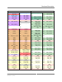
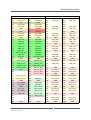
Table 8. Pin assignment of COM Express connectors J1 and J2
J1
J2
A1
GND
B1
GND
C1
GND
D1
GND
A2
GBE0_MDI3-
B2
GBE0_ACT#
C2
GND
D2
GND
A3
GBE0_MDI3+
B3
LPC_FRAME#
C3
USB_SSRX2-
D3
USB_SSTX2-
A4
GBE0_LINK100#
B4
LPC_AD0
C4
USB_SSRX2+
D4
USB_SSTX2+
A5
GBE0_LINK1000#
B5
LPC_AD1
C5
GND
D5
GND
A6
GBE0_MDI2-
B6
LPC_AD2
C6
USB_SSRX1-
D6
USB_SSTX1-
A7
GBE0_MDI2+
B7
LPC_AD3
C7
USB_SSRX1+
D7
USB_SSTX1+
A8
GBE0_LINK#
B8
LPC_DRQ0#
C8
GND
D8
GND
A9
GBE0_MDI1-
B9
LPC_DRQ1#
C9
USB_SSRX3-
D9
USB_SSTX3-
A10
GBE0_MDI1+
B10
LPC_CLK
C10
USB_SSRX3+
D10
USB_SSTX3+
A11
GND
B11
GND
C11
GND
D11
GND
A12
GBE0_MDI0-
B12
PWRBTN#
C12
USB_SSRX4-
D12
USB_SSTX4-
A13
GBE0_MDI0+
B13
SMB_CK
C13
USB_SSRX4+
D13
USB_SSTX4+
A14
GBE0_CTREF
B14
SMB_DAT
C14
GND
D14
GND
A15
SUS_S3#
B15
SMB_ALERT#
C15
SDVO_STALL+
D15
DDI1_CTRLCLK_AUX+
A16
SATA0_TX+
B16
SATA1_TX+
C16
SDVO_STALL-
D16
DDI1_CTRLCLK_AUX-
A17
SATA0_TX-
B17
SATA1_TX-
C17
-
D17
-
A18
SUS_S4#
B18
SUS_STAT#
C18
-
D18
-
A19
SATA0_RX+
B19
SATA1_RX+
C19
PCIE_RX2+
D19
PCIE_TX2+
A20
SATA0_RX-
B20
SATA1_RX-
C20
PCIE_RX2-
D20
PCIE_TX2-
A21
GND
B21
GND
C21
GND
D21
GND
A22
SATA4_TX+
B22
SATA5_TX+
C22
-
D22
-
A23
SATA4_TX-
B23
SATA5_TX-
C23
-
D23
-
A24
SUS_S5#
B24
PWR_OK
C24
DDI1_HPD
D24
-
A25
SATA4_RX+
B25
SATA5_RX+
C25
SDVO_INT+
D25
-
MEN Mikro Elektronik GmbH
20CB70C00 E1 – 2014-06-18
38
Functional Description
J1
J2
A26
SATA4_RX-
B26
SATA5_RX-
C26
SDVO_INT-
D26
DDI1_PAIR0+
A27
BATLOW#
B27
-
C27
-
D27
DDI1_PAIR0-
A28
(S)ATA_ACT#
B28
HDA_SDIN2
C28
-
D28
-
A29
HDA_SYNC
B29
HDA_SDIN1
C29
SDVO_TVCLKIN+
D29
DDI1_PAIR1+
A30
HDA1_RST#
B30
HDA_SDIN0
C30
SDVO_TVCLKIN-
D30
DDI1_PAIR1-
A31
GND
B31
GND
C31
GND
D31
GND
A32
HDA1_BITCLK
B32
SPKR
C32
DDI2_CTRLCLK_AUX+
D32
DDI1_PAIR2+
A33
HDA1_SDOUT
B33
-
C33
DDI2_CTRLDATA_AUX-
D33
DDI1_PAIR2-
A34
-
B34
-
C34
DDI2_DDC_AUX_SEL
D34
DDI1_DDC_AUX_SEL
A35
THRMTRIP#
B35
THRM#
C35
-
D35
-
A36
USB10-
B36
USB11-
C36
DDI3_CTRLCLK_AUX+
D36
DDI1_PAIR3+
A37
USB10+
B37
USB11+
C37
DDI3_CTRLDATA_AUX-
D37
DDI1_PAIR3-
A38
USB_10_11_OC#
B38
USB_8_9_OC#
C38
DDI3_DDC_AUX_SEL
D38
-
A39
USB8-
B39
USB9-
C39
DDI3_PAIR0+
D39
DDI2_PAIR0+
A40
USB8+
B40
USB9+
C40
DDI3_PAIR0-
D40
DDI2_PAIR0-
A41
GND
B41
GND
C41
GND
D41
GND
A42
USB2-
B42
USB3-
C42
DDI3_PAIR1+
D42
DDI2_PAIR1+
A43
USB2+
B43
USB3+
C43
DDI3_PAIR1-
D43
DDI2_PAIR1-
A44
USB_2_3_OC#
B44
USB_0_1_OC#
C44
DDI3_HPD
D44
DDI2_HPD
A45
USB1-
B45
USB1-
C45
-
D45
-
A46
USB1+
B46
USB1+
C46
DDI3_PAIR2+
D46
DDI2_PAIR2+
A47
VCC_RTC
B47
EXCD1_PERST#
C47
DDI3_PAIR2-
D47
DDI2_PAIR2-
A48
EXCD0_PERST#
B48
EXCD1_CPPE#
C48
-
D48
-
A49
EXCD0_CPPE#
B49
SYS_RESET#
C49
DDI3_PAIR3+
D49
DDI2_PAIR3+
A50
LPC_SERIRQ
B50
CB_RESET#
C50
DDI3_PAIR3-
D50
DDI2_PAIR3-
A51
GND
B51
GND
C51
GND
D51
GND
A52
PCIE_TX3+
B52
PCIE_RX3+
C52
PEG_RX0+
D52
PEG_TX0+
A53
PCIE_TX3-
B53
PCIE_RX3-
C53
PEG_RX0-
D53
PEG_TX0-
A54
GPI0
B54
GPO1
C54
-
D54
-
A55
PCIE_TX4+
B55
PCIE_RX4+
C55
PEG_RX1+
D55
PEG_TX1+
A56
PCIE_TX4-
B56
PCIE_RX4-
C56
PEG_RX1-
D56
PEG_TX1-
A57
GND
B57
GPO2
C57
-
D57
GND
A58
PCIE_TX8+
B58
PCIE_RX8+
C58
PEG_RX2+
D58
PEG_TX2+
A59
PCIE_TX8-
B59
PCIE_RX8-
C59
PEG_RX2-
D59
PEG_TX2-
A60
GND
B60
GND
C60
GND
D60
GND
MEN Mikro Elektronik GmbH
20CB70C00 E1 – 2014-06-18
39
Functional Description
J1
J2
A61
PCIE_TX7+
B61
PCIE_RX7+
C61
PEG_RX3+
D61
PEG_TX3+
A62
PCIE_TX7-
B62
PCIE_RX7-
C62
PEG_RX3-
D62
PEG_TX3-
A63
GPI1
B63
GPO3
C63
-
D63
-
A64
PCIE_TX6+
B64
PCIE_RX6+
C64
-
D64
-
A65
PCIE_TX6-
B65
PCIE_RX6-
C65
PEG_RX4+
D65
PEG_TX4+
A66
GND
B66
WAKE0#
C66
PEG_RX4-
D66
PEG_TX4-
A67
GPI2
B67
WAKE1#
C67
-
D67
GND
A68
PCIE_TX5+
B68
PCIE_RX5+
C68
PEG_RX5+
D68
PEG_TX5+
A69
PCIE_TX5-
B69
PCIE_RX5-
C69
PEG_RX5-
D69
PEG_TX5-
A70
GND
B70
GND
C70
GND
D70
GND
A71
LVDS_A0+
B71
LVDS_B0+
C71
PEG_RX6+
D71
PEG_TX6+
A72
LVDS_A0-
B72
LVDS_B0-
C72
PEG_RX6-
D72
PEG_TX6-
A73
LVDS_A1+
B73
LVDS_B1+
C73
GND
D73
GND
A74
LVDS_A1-
B74
LVDS_B1-
C74
PEG_RX7+
D74
PEG_TX7+
A75
LVDS_A2+
B75
LVDS_B2+
C75
PEG_RX7-
D75
PEG_TX7-
A76
LVDS_A2-
B76
LVDS_B2-
C76
GND
D76
GND
A77
LVDS_VDD_EN
B77
LVDS_B3+
C77
-
D77
-
A78
LVDS_A3+
B78
LVDS_B3-
C78
PEG_RX8+
D78
PEG_TX8+
A79
LVDS_A3-
B79
LVDS_BKLT_EN
C79
PEG_RX8-
D79
PEG_TX8-
A80
GND
B80
GND
C80
GND
D80
GND
A81
LVDS_A_CK+
B81
LVDS_B_CK+
C81
PEG_RX9+
D81
PEG_TX9+
A82
LVDS_A_CK-
B82
LVDS_B_CK-
C82
PEG_RX9-
D82
PEG_TX9-
A83
LVDS_I2C_CK
B83
LVDS_BKLT_CTRL
C83
-
D83
-
A84
LVDS_I2C_DAT
B84
VCC_5V_SBY
C84
GND
D84
GND
A85
GPI3
B85
VCC_5V_SBY
C85
PEG_RX10+
D85
PEG_TX10+
A86
-
B86
VCC_5V_SBY
C86
PEG_RX10-
D86
PEG_TX10-
A87
-
B87
VCC_5V_SBY
C87
GND
D87
GND
A88
PCIE_CLK_[1]+
B88
-
C88
PEG_RX10+
D88
PEG_TX10+
A89
PCIE_CLK_[1]-
B89
VGA_RED
C89
PEG_RX10-
D89
PEG_TX10-
A90
GND)
B90
GND
C90
GND
D90
GND
A91
SPI_POWER
B91
VGA_GRN
C91
PEG_RX12+
D91
PEG_TX12+
A92
SPI_MISO
B92
VGA_BLU
C92
PEG_RX12-
C92
PEG_TX12-
A93
GPO0
B93
VGA_HSYNC
C93
GND
D93
GND
A94
SPI_CLK
B94
VGA_VSYNC
C94
PEG_RX13+
D94
PEG_TX13+
A95
SPI_MOSI
B95
VGA_I2C_CK
C95
PEG_RX13-
D95
PEG_TX13-
A96
TPM_PP
B96
VGA_I2C_DAT
C96
GND
D96
GND
A97
-
B97
SPI1_CS#
C97
-
D97
-
A98
-
B98
-
C98
PEG_RX14+
D98
PEG_TX14+
A99
-
B99
-
C99
PEG_RX14-
D99
PEG_TX14-
A100
GND
B100
GND
C100
GND
D100
GND
MEN Mikro Elektronik GmbH
20CB70C00 E1 – 2014-06-18
40
Functional Description
J1
J2
A101
-
B101
-
C101
PEG_RX15+
D101
PEG_TX15+
A102
-
B102
-
C102
PEG_RX15-
D102
PEG_TX15-
A103
LID#
B103
SLEEP#
C103
GND
D103
GND
A104
VCC_12V
B104
VCC_12V
C104
VCC_12V
D104
VCC_12V
A105
VCC_12V
B105
VCC_12V
C105
VCC_12V
D105
VCC_12V
A106
VCC_12V
B106
VCC_12V
C106
VCC_12V
D106
VCC_12V
A107
VCC_12V
B107
VCC_12V
D107
VCC_12V
C107
VCC_12V
A108
VCC_12V
B108
VCC_12V
D108
VCC_12V
C108
VCC_12V
A109
VCC_12V
B109
VCC_12V
C109
VCC_12V
D109
VCC_12V
A110
GND
B110
GND
C110
GND
D110
GND
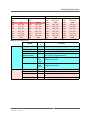
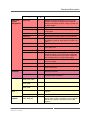
Table 9. Signal Mnemonics
Signal
Ethernet
Power
Function
GBE0_ACT#
out
Signal for activity status LED, port 0
GBE0_CTREF
out
Port 0 reference voltage
GBE0_LINK#
out
Signal for link status LED, port 0
GBE0_MDI[0:3]+,
GBE0_MDI[0:3]-
in/out
Media Dependent Interface data, differential pairs
0 to 3, port 0 (Gigabit Ethernet)
GBE0_LINK100#
Open
drain
output
Gigabit Ethernet Controller 0 100 Mbit / sec link
indicator, active low
GBE0_LINK1000#
Open
drain
output
Gigabit Ethernet Controller 0 1000 Mbit / sec link
indicator, active low
GND
-
Ground
VCC_12V
in
Primary power input: +12V nominal
VCC_RTC
in
Real-time clock circuit-power input. Nominally +3.0
V
VCC_5V_SBY
in
Standby power input
MEN Mikro Elektronik GmbH
20CB70C00 E1 – 2014-06-18
Directio
n
41
Functional Description
Signal
Power and
System
Management
Thermal
Protection
PCI Express
PCI Express
Card
PCI Express
Graphics
Function
BATLOW#
in
Indicates that external battery is low. This port
provides a battery-low signal to the module for
orderly transitioning to power saving or power cutoff ACPI modes.
CB_RESET#
out
Reset output from module to carrier board
LID#
in
LID button, used by the ACPI operating system for
a LID switch
PWR_OK
in
Power OK signal from external main power supply
PWRBTN#
in
Power button to bring system out of S5 (soft off)
SLEEP#
in
Sleep button, used by the ACPI operating system
to bring the system to sleep state or to wake it up
again
SYS_RESET#
in
Reset button input
WAKE0#
in
Wake signal from PCIe device to wake CB70C
from sleep state
WAKE1#
in
General purpose wake-up signal
SUS_S3#
out
Indicates system is in Suspend to RAM state.
Active low output. An inverted copy of SUS_S3#
on the Carrier Board may be used to enable the
non-standby power on a typical ATX supply
SUS_S4#
out
Indicates system is in Suspend to Disk state.
Active low output
SUS_S5#
out
Indicates system is in Soft Off state
SUS_STAT#
out
Indicates imminent suspend operation; used to
notify LPC devices
THRM#
in
Input from off-Module temp sensor indicating an
over-temp situation.
THERMTRIP#
out
Active low output indicating that the CPU has
entered thermal shutdown.
PCIE_CLK_REF+,
PCIE_CLK_REF-
out
Reference clock output for all PCI Express lanes
PCIE_RX0+,
PCIE_RX0-
in
Differential PCIe receive lines, lane 0
PCIE_TX0+,
PCIE_TX0-
out
Differential PCIe transmit lines, lane 0
EXCD0_CPPE#
in
PCI ExpressCard: PCI Express capable card
request
EXCD0_PERST#
out
PCI ExpressCard: reset
PEG_RX[0:15]+,
PEG_RX[0:15]-
in
PCI Express Graphics Receive Differential Pair or
regular PCIe 1x16 or 2x8. SDVO and PCI Express
Interface for Graphics architecture are muxed
together
MEN Mikro Elektronik GmbH
20CB70C00 E1 – 2014-06-18
Directio
n
42
Functional Description
Signal
LVDS
DDI
VGA
Function
PEG_TX[0:15]+,
PEG_TX[0:15]-
out
PCI Express Graphics Transmit Differential Pair or
regular PCIe 1x16 or 2x8
PEG_ENABLE#
in
Strap to enable PCI Express x16 external graphics
interface
PEG_LANE_RV#
in
PCI Express Graphics lane reversal input strap
LVDS_A_CK+,
LVDS_A_CK-
out
Differential LVDS clock output, port A
LVDS_A[0:3]+,
LVDS_A[0:3]-
out
Differential LVDS lines, port A
LVDS_B_CK+,
LVDS_B_CK-
out
Differential LVDS clock output, port B
LVDS_B[0:3]+,
LVDS_B[0:3]-
out
Differential LVDS lines, port B
LVDS_BKLT_CTRL
out
LVDS panel backlight brightness control
LVDS_BKLT_EN
out
LVDS panel backlight enable
LVDS_I2C_CK
in/out
I2C clock output for LVDS display use
LVDS_I2C_DAT
in/out
I2C data line for LVDS display use
LVDS_VDD_EN
out
LVDS panel power enable
DDI[1:3]_PAIR[0:3]+ out
DDI[1:3]_PAIR[0:3]-
Digital Display Interface 1 to 3 Pair[0:3] differential
pairs
DDI[1:3]_HPD
in
Digital Display Interface Hot-Plug Detect
DDI2_CTRLCLK_A
UX+
in/out
Multiplexed DDI[0:2] Data Channel Clock & AUX +
DDI3_CTRLDATA_
AUX-
in/out
Multiplexed DDI[0:2] Data Channel Data & AUX -
DDI[0:2]_DDC_AUX in
_SEL
DDI[0:2] DDC/AUX Select
VGA_RED
out
Red for monitor. Analog DAC output, designed to
drive a 37.5 Ohm equivalent load
VGA_GRN
out
Green for monitor. Analog DAC output, designed
to drive a 37.5 Ohm equivalent load
VGA_BLU
out
Blue for monitor. Analog DAC output, designed to
drive a 37.5 Ohm equivalent load
VGA_HSYNC
out
Horizontal sync output to VGA monitor
VGA_VSYNC
out
Vertical sync output to VGA monitor
VGA_I2C_CK
in/out
DDC clock line (I2C port dedicated to identify VGA
monitor capabilities)
VGA_I2C_DAT
in/out
DDC data line
MEN Mikro Elektronik GmbH
20CB70C00 E1 – 2014-06-18
Directio
n
43
Functional Description
Signal
SDVO
SATA
USB
Directio
n
Function
SDVO_STALL+
SDVO_STALL-
in
Serial Digital Video Field Stall input differential
pair.
SDVOC_INT+
SDVOC_INT-
in
Serial Digital Video C interrupt input differential
pair.
SDVO_TVCLKIN+
SDVO_TVCLKINI
in
Serial Digital Video TVOUT synchronization clock
input differential pair.
SATA0_RX+,
SATA0_RX-
in
Differential SATA receive lines, port 0
SATA0_TX+,
SATA0_TX-
out
Differential SATA transmit lines, port 0
SATA1_RX+,
SATA1_RX-
in
Differential SATA receive lines, port 1
SATA1_TX+,
SATA1_TX-
out
Differential SATA transmit lines, port 1
SATA4_RX+,
SATA4_RX-
in
Differential SATA receive lines, port 4
SATA4_TX+,
SATA4_TX-
out
Differential SATA transmit lines, port 4
SATA5_RX+,
SATA5_RX-
in
Differential SATA receive lines, port 5
SATA5_TX+,
SATA5_TX-
out
Differential SATA transmit lines, port 5
SATA_ACT#
in/out
SATA activity indicator
USB0+, USB0-
in/out
Differential USB 2.0 lines, port 0
USB1+, USB1-
in/out
Differential USB 2.0 lines, port 1
USB2+, USB2-
in/out
Differential USB 2.0 lines, port 2
USB3+, USB3-
in/out
Differential USB 2.0 lines, port 3
USB4+, USB4-
in/out
Differential USB 2.0 lines, port 4
USB5+, USB5-
in/out
Differential USB 2.0 lines, port 5
USB_0_1_OC#
in
USB overcurrent sense, ports 0 and 1
USB_2_3_OC#
in
USB overcurrent sense, ports 2 and 3
USB_4_5_OC#
in
USB overcurrent sense, ports 4 and 5
USB_SSTX[0:3]+
USB_SSTX[0:3]-
out
Differential USB 3.0 transmit lines, port 0 to 3
USB_SSRX[0:3]+
in
Differential USB 3.0 receive lines, port 0 to 3
USB_SSRX[0:3]-
MEN Mikro Elektronik GmbH
20CB70C00 E1 – 2014-06-18
44
Functional Description
Signal
HD Audio
LPC
SPI
Directio
n
Function
HDA_IO
-
Reference voltage for external HDA codec I/O
voltage level
HDA_BIT_CLK
in/out
HD audio serial data clock
HDA_RST#
out
HD audio reset
HDA_SDIN[0:2]
in/out
HD audio serial data in
HDA_SDOUT
out
HD audio serial data out
HDA_SYNC
out
HD audio synchronization
LPC_AD[0:3]
in/out
LPC multiplexed address, command and data bus
LPC_FRAME#
out
LPC frame indicates the start of an LPC cycle
LPC_DRQ[0:1]#
in
LPC serial DMA request
LPC_SERIRQ
in/out
LPC serial interrupt
LPC_CLK
out
LPC clock output - 33MHz nominal
SPI_CS#
out
Chip select for Carrier Board SPI - may be sourced
from chipset SPI0 or SPI1
SPI_MISO
in
Data out from Module to Carrier SPI
SPI_MOSI
out
Data in to Module from Carrier SPI
SPI_CLK
out
Clock from Module to Carrier SPI
SPI_POWER
out
Power supply for Carrier Board SPI – sourced from
Module – nominally 3.3V. The Module shall
provide a minimum of 100mA on SPI_POWER.
Carriers shall use less than 100mA of
SPI_POWER. SPI_POWER shall only be used to
power SPI devices on the Carrier.
SMB
SMB_CK
in/out
System Management Bus bidirectional clock line.
Power sourced through 5V standby rail and main
power rails.
SMB_DAT
in/out
System Management Bus bidirectional data line.
Power sourced through 5V standby rail and main
power rails.
SMB_ALERT#
MEN Mikro Elektronik GmbH
20CB70C00 E1 – 2014-06-18
System Management Bus Alert – active low input
can be used to generate an SMI# (System
Management Interrupt) or to wake the system.
Power sourced through 5V standby rail and main
power rails.
45
Functional Description
Signal
Miscellaneous SPKR
Directio
n
out
Function
Output for audio enunciator - the "speaker" in PCAT systems.
This port provides the PC beep signal and is
mostly intended for debugging purposes.
TPM_PP
in
Physical Presence pin of Trusted Platform Module
(TPM). Active high.
TPM chip has an internal pull down. This signal is
used to indicate Physical Presence to the TPM.
MEN Mikro Elektronik GmbH
20CB70C00 E1 – 2014-06-18
46
UEFI Firmware (BIOS)
3
UEFI Firmware (BIOS)
3.1
InsydeH2O Framework
The CB70C is equipped with an InsydeH2O setup utility from Insyde Software.
InsydeH2O is Insyde Software's firmware product line designed to replace
traditional PC BIOS. It is an implementation of the Intel's Platform Innovation
Framework for UEFI/EFI. The UEFI/EFI specification defines a new model for the
interface between operating systems and platform firmware. This interface consists
of data tables that contain platform-related information, plus boot and runtime
service calls that are available to the operating system and its loader. Together, these
provide a standard environment for booting an operating system and running preboot applications. This product line is the next generation of PC BIOS technology.
3.2
UEFI Firmware System Setup Utility
The CB70C UEFI firmware comes with a Setup Configuration Utility (SCU),
simply called "system setup", as commonly known.
The ">" character in front of a menu item means that a sub-menu is available. An
"x" in front of a menu item means that there is a configuration option which needs to
be activated through a higher configuration option before being accessible.
The CB70C BIOS has two configuration modes. One mode shows only a selection
of the most important items and hides items where normally no changes in the
settings are required. This manual only describes the short mode. You can easily
switch between the two modes via a menu item About this Software.
The settings shown in the following description are usually the default settings.
3.2.1
Main
InsydeH2O Setup Utility
Main
Advanced
Security
Power
Rev. 3.5
Boot
Exit
InsydeH2O Version
CB70-02 1.18
Processor Type
Intel(R) Core(TM) i7-3615QE CPU @ 2.30 GHz
System Bus Speed
100 MHz
System Memory Speed
1600 MHz
MEN BMC Rev
1.6.0
MEN Board Model/Rev
Not detected
MEN Board S/N
2344
Cache RAM
256 kB
Total Memory
16384 MB
Channel A
SODIMM 0
8192 MB
SODIMM 1
[Not installed]
MEN Mikro Elektronik GmbH
20CB70C00 E1 – 2014-06-18
47
UEFI Firmware (BIOS)
InsydeH2O Setup Utility
Rev. 3.5
Channel B
SODIMM 0
8192 MB
SODIMM 1
[Not installed]
Platform Configuration
CPU ID:
0x306A9
Microcode Rev:
0x15
Number of Core:
4
Number of Thread:
8
SMX/TXT:
Supported
VT-d:
Supported
VMX:
Supported
PCH-Rev:
04 (PPT-C1 Stepping)
VBIOS Ver.:
2137
Intel ME Version:
8.1.20.1336
SA-Rev:
09 (E1 Stepping)
Language
[English]
System Time
[hh:mm:ss]
System Date
[mm/dd/yyyy]
About this Software
Full configuration mode
[No]
F1 Help
Select Item
F5/F6 Change Values
F9 Setup Defaults
Esc Exit
Select Menu
Enter Select >
Submenu
F10 Save and Exit
InsydeH2O Version / Processor Type / System Bus Speed / System
Memory Speed/MEN Board Rev/ MEN BMC Rev / MEN Board Rev/ MEN
Board S/N/ Cache RAM/ Total Memory / SODIMM 0 / SODIMM 1/Platform
Configuration/CPU ID/Microcode Rev/Number of Core/Number of
Thread/SMX/TXT/VT-d/VMX/PCH-Rev/VBIOS Version/Intel ME Version/
SA-Rev
Description
You cannot change any values in these fields. They are only for
information. The values shown in the menu above are example
values.
Language
Description
Select the default language.
Options
English
MEN Mikro Elektronik GmbH
20CB70C00 E1 – 2014-06-18
48
UEFI Firmware (BIOS)
System Time
Description
Change the internal clock.
Options
hh
Hours (Valid range from 0 to 23)
mm
Minutes (Valid range from 0 to 59)
ss
Seconds (Valid range from 0 to 59)
System Date
Description
Change the date
Options
mm
Month (Valid range from 1 to 12)
dd
Day (Valid range from 1 to 31)
yyyy
Year (Valid range from 2000 to 2099)
About this Software
Description
Under this item you can find information about the UEFI BIOS.
Full Configuration Mode
Description
The CB70C BIOS has two configuration modes. One mode shows
only a selection of the most important items and hides items where
normally no changes in the settings are required.
Options
Yes
Enable full configuration mode
No
Disable full configuration mode
MEN Mikro Elektronik GmbH
20CB70C00 E1 – 2014-06-18
49
UEFI Firmware (BIOS)
3.2.2
Advanced Menu
InsydeH2O Setup Utility
Main
Advanced
Security
Power
Rev. 3.5
Boot
Exit
>Boot Configuration
>Peripheral Configuration
>IDE Configuration
>Thermal Configuration
>Video Configuration
>USB Configuration
>Chipset Configuration
>ACPI Table/Features Control
>Active Management Technology Support
>PCI Express Configuration
>Console Redirection
F1 Help
Select Item
F5/F6 Change Values
F9 Setup Defaults
Esc Exit
Select Menu
Enter Select >
Submenu
F10 Save and Exit
MEN Mikro Elektronik GmbH
20CB70C00 E1 – 2014-06-18
50
UEFI Firmware (BIOS)
3.2.2.1
Boot Configuration — Sub-menu
SCU Resolution
Add additional delay during BIOS
boot process
Power Supply Type
Watchdog
PWRON after PWR-Fail
ATX_PWRGD Failure Mode
External PS Control
Platform Reset Management
[1024 x 768]
[No delay]
[ATX]
[Off]
[On]
[Check at Start-Up]
[Switched]
[RESET_IN is enabled]
SCU Resolution
Description
Change resolution of setup utility.
Options
640 x 480
800 x 600
Add additional delay during BIOS boot process
Description
Helpful for init delay of peripheral boards
Options
No delay
100 ms delay
200 ms delay
300 ms delay
400 ms delay
500 ms delay
600 ms delay
700 ms delay
800 ms delay
Power Supply Type
Description
Selects the type of power supply
Options
AT
ATX
Watchdog
Description
Enables or disables the CB70C Watchdog.
Options
Off
10 min
1 min
15 min
2 min
20 min
5 min
30 min
PWRON after PWR-Fail
Description
Sets the system power status when power returns to the system
from a power failure situation.
Options
On
Off
Former State
MEN Mikro Elektronik GmbH
20CB70C00 E1 – 2014-06-18
51
UEFI Firmware (BIOS)
ATX_PWRGD Failure Mode
Description
Determines the system behavior in case of a failure at the ATX
power good signal
Options
Check at StartUp
Check always
External PS Control
Description
Controls the external Power Supply
Options
Always on
Switched
Platform Reset Management
Description
Controls the external Power Supply
Options
Always on
3.2.2.2
Switched
Peripheral Configuration — Sub-menu
Serial Port A
[Auto]
Infrared Port
HD Audio
HD Audio internal HDMI codec
HD Audio PME enable
LAN-1
[Disabled]
[Auto]
[Disabled]
[Disabled]
[Enabled]
Serial Port A
Description
Configures Serial Port A options.
Options
Auto
Configuration is determined automatically by
the BIOS or operating system.
Disabled
No configuration.
Enabled
User configuration.
Infrared Port
Description
Configures Infrared Port options.
Options
Auto
Configuration is determined automatically by
the BIOS or operating system.
Disabled
No configuration.
Enabled
User configuration.
MEN Mikro Elektronik GmbH
20CB70C00 E1 – 2014-06-18
52
UEFI Firmware (BIOS)
HD Audio
Description
Enables or disables the Audio controller.
Options
Auto
The controller is enabled if a codec is found.
Disabled
The controller is disabled even when there is an
audio codec.
Enabled
The controller is enabled independent of the
presence of a codec.
HD Audio internal HDMI codec
Description
Enables or disables the HD Audio internal HDMI codec.
Options
Enabled
Disabled
HD Audio PME Enable
Description
Enables or disables the HD Audio PME enable.
Options
Enabled
Disabled
LAN-1
Description
Enables or disables Intel 82579 GbE (AMT).
Options
Enabled
MEN Mikro Elektronik GmbH
20CB70C00 E1 – 2014-06-18
Disabled
53
UEFI Firmware (BIOS)
3.2.2.3
IDE Configuration — Sub-menu
IDE Controller
HDC Configure as
>Software Feature Mask Configuration
Aggressive LPM Support
SATA Port 0
SATA Port Hot Plug
Spin-Up Device
SATA Device Type
Port Multiplier
SATA Port 1
SATA Port Hot Plug
Spin-Up Device
SATA Device Type
Port Multiplier
SATA Port 2
SATA Port 3
SATA Port 4
SATA Port Hot Plug
Spin-Up Device
SATA Device Type
Port Multiplier
SATA Port 5
SATA Port Hot Plug
Spin-Up Device
SATA Device Type
Port Multiplier
[Enabled]
[AHCI]
[Enabled]
[Enabled]
[Disabled]
[Disabled]
[Hard Disk Drive]
[Disabled]
[Enabled]
[Disabled]
[Disabled]
[Hard Disk Drive]
[Disabled]
[Disabled]
[Disabled]
[Enabled]
[Disabled]
[Disabled]
[Hard Disk Drive]
[Disabled]
[Enabled]
[Disabled]
[Disabled]
[Hard Disk Drive]
[Disabled]
IDE Controller
Description
Enables or disables the IDE controllers.
Options
Enabled
Disabled
HDC Configure as
Description
Set hard disk controller configure type.
Options
IDE
RAID
AHCI
>Software Feature Mask Configuration - Sub-Menu
HDD Unlock
LED Locate
[Enabled]
[Enabled]
The RAID OROM/RST driver will refer to SWFM configuration to enable/disable the
storage feature
MEN Mikro Elektronik GmbH
20CB70C00 E1 – 2014-06-18
54
UEFI Firmware (BIOS)
HDD Unlock
Description
Enables or disables the unlock button for protected drives in the Intel
RST manager.
Options
Enabled
Disabled
LED Locate
Description
If enabled, it is indicated that the LED/SGPIO hardware is attached
and the pin to locate the feature is enabled in the OS.
Options
Enabled
Disabled
Aggressive LPM Support
Description
Enables or disables aggressive LPM support.
Options
Enabled
Disabled
SATA Port 0/1/2/3/4/5
Description
Enables or disables SATA ports.
Options
Enabled
Disabled
SATA Port Hot Plug
Description
Enables or disables the SATA Port Hot Plug feature.
Options
Enabled
Disabled
Spin-Up Device
Description
Enables or disables Spin-up device.
Options
Enabled
Disabled
SATA Device Type
Description
Selects the SATA device.
Options
Hard Disk Drive
Solid State Drive
Port Multiplier
Description
Enables or disables port multiplier.
Options
Enabled
MEN Mikro Elektronik GmbH
20CB70C00 E1 – 2014-06-18
Disabled
55
UEFI Firmware (BIOS)
3.2.2.4
Thermal Configuration — Sub-menu
>Platform Thermal Configuration
>CPU Thermal Configuration
Platform Thermal Configuration - Sub-Menu
Automatic Thermal Reporting
[Enabled]
Automatic Thermal Reporting
Description
Enables or disables the Intel Adaptive Thermal monitor
Options
Enabled
Disabled
CPU Thermal Configuration - Sub-Menu
DTS
Bidirectional PROCHOT#
ACPI 3.0 T-States
[Disabled]
[Disabled]
[Disabled]
DTS
Description
Enables CPU Digital Thermal Sensor function. Out of spec: ACPI
Thermal Management uses EC reported temperature values and
DTS SMM is used to handle Out of Spec condition.
Options
Critical reporting
Disabled
Enabled
Bidirectional PROCHOT#
Description
This value cannot be changed.
Options
Disabled
ACPI 3.0 T-States
Description
Enable or disable ACPI 3.0 T-States
Options
Disabled
MEN Mikro Elektronik GmbH
20CB70C00 E1 – 2014-06-18
Enabled
56
UEFI Firmware (BIOS)
3.2.2.5
Video Configuration — Sub-menu
Primary Display
>Internal Graphic Device
[Auto]
Primary Display
Description
Selects Primary Display Mode.
Options
Auto
IGFX
PEG
PCI
>Internal Graphic Device - Sub-Menu
Internal Graphics Device
IGD - Gtt Size
IGD - Aperture Size
IGD - DVMT Pre-Allocated
IGD - Boot Type
[Auto]
[2 MB]
[256 MB]
[64 MB]
[VBIOS Default]
Internal Graphics Device
Description
Enables or disables the Internal Graphics Device (IGD).
Options
Enabled
The IGD is enabled in any case.
Disabled
The IGD is disabled
Auto
The IGD is enabled only when a monitor is
found
IGD - Gtt Size
Description
Selects the size of the Gtt (graphics translation table) memory.
Options
1 MB
2 MB
IGD - Aperture Size
Description
Selects the size of the system memory that is used by the Internal
Graphics Device.
Options
128 MB
256 MB
512 MB
MEN Mikro Elektronik GmbH
20CB70C00 E1 – 2014-06-18
57
UEFI Firmware (BIOS)
IGD - DVMT Pre-Allocated
Description
Select DVMT Pre-Allocated (Fixed) Graphics Memory size used by
the Internal Graphics Device.
Options
0 MB
32 MB
64 MB
96 MB
128 MB
160 MB
192 MB
224 MB
256 MB
288 MB
320 MB
352 MB
384 MB
416 MB
448 MB
480 MB
512 MB
1024 MB
IGD - Boot Type
Description
Select the video device that will be activated during POST
Options
VBIOS Default
LFP-SDVO
CRT
EFP
LFP
TV-SDVO
CRT+LFP
CRT+LFP-SDVO
TV
CRT+EFP
3.2.2.6
USB Configuration — Sub-menu
USB BIOS Support
EHCI 1
EHCI 2
Pre-Port Control
[Enabled]
[Enabled]
[Enabled]
[Disabled]
USB BIOS Support
Description
If this menu item is enabled it is possible to boot from USB devices
and use a USB keyboard under DOS. Cannot be changed. No
BIOS setup is possible if this item is not enabled.
Options
Enabled
EHCI 1/2
Description
Enable/Disable EHCI 1/2.
Options
Enabled
Disabled
Pre-Port Control
Description
Enable/Disable the pre-port disable control override.
Options
Enabled
MEN Mikro Elektronik GmbH
20CB70C00 E1 – 2014-06-18
Disabled
58
UEFI Firmware (BIOS)
3.2.2.7
Chipset Configuration
Setup warning
Setting items on this screen to incorrect values may cause your system
to malfunction!
VT-d
[Enabled]
VT-d
Description
Check to enable the VT-d (Intel Virtualization Technology for
Directed I/O) function.
Options
Enabled
3.2.2.8
Disabled
ACPI Table/Feature Control
FACP - RTC S4 Wakeup
APIC - IO APIC Mode
TCO Watchdog Support
Watchdog ACPI Table
[Enabled]
[Enabled]
[Enabled]
[Enabled]
FACP - RTC S4 Wakeup
Description
Value only for ACPI. Enable/Disable for S4 Wakeup from RTC.
Options
Enabled
Disabled
APIC - IO APIC Mode
Description
This item is valid only for WIN2k and WINXP.Also, a fresh install of
the OS must occur when APIC Mode is desired.Test the IO ACPI by
setting item to Enable.The APIC Table will then be pointed to by the
RSDT, the Local APIC will be initialized, and the proper enable bits
will be set in chipset.
Options
Enabled
Disabled
TCO Watchdog Support
Description
Enables or disables TCO Watchdog Support.
Options
Enabled
Disabled
Watchdog ACPI Table
Description
Enables or disables Watchdog ACPI Table.
Options
Enabled
MEN Mikro Elektronik GmbH
20CB70C00 E1 – 2014-06-18
Disabled
59
UEFI Firmware (BIOS)
3.2.2.9
Active Management Technology Support
Intel AMT Support
[Enabled]
Intel AMT Support
Description
Enable/disable Intel Active Management Technology BIOS
extension. Note: iAMT H/W is always enabled. This option just
controls the BIOS extension execution.
Options
Enabled
Disabled
3.2.2.10 PCI Express Configuration
PCIE Port assigned to LAN
>PCI Express Root Port 1
>PCI Express Root Port 2
>PCI Express Root Port 3
>PCI Express Root Port 4
>PCI Express Root Port 5
>PCI Express Root Port 6
>PCI Express Root Port 7
>PCI Express Root Port 8
2
PCIE Port assigned to LAN
Description
Determines the number of the PCI Express port which is assigned
to the LAN interface.
Options
2
>PCI Express Root Port 1/2/3/4/5/6/7/8 - Sub-Menu
>PCI Express Root Port 1
[Enabled]
PCI Express Root Port 1/2/3/4/5/6/7/8
Description
Enables or disables PCI Express ports. If PCI Express Root Port 1
is disabled, PCI Express Root Ports 2 to 7 will also be disabled.
Options
Enabled
MEN Mikro Elektronik GmbH
20CB70C00 E1 – 2014-06-18
Disabled
60
UEFI Firmware (BIOS)
3.2.2.11 Console Redirection — Sub-menu
Console Serial Redirect
Information Wait Time
Serial Port
Terminal Type
Baud Rate
Data Bits
Parity
Stop Bits
Flow Control
C.R. After Post
Text Mode Resolution
ACPI SPCR Table
[Enabled]
[5 Second]
[COM A]
[VT100]
[115200]
[8 Bits]
[None]
[1 Bit]
[None]
[Yes]
[AUTO]
[Disabled]
Console Serial Redirect
Description
Enables or disables the console redirection feature.
Options
Enabled
Disabled
Information Wait Time
Description
Sets the information wait time value.
Options
0 seconds
2 seconds
5 seconds
10 seconds
30 seconds
Serial Port
Description
Selects the serial port.
Options
COM A
COM B
COM C
COM D
PCI Devices
All Ports
Terminal Type
Description
Selects the terminal type.
Options
VT100
VT100+
VT_UTF8
PC_ANSI
Baud Rate
Description
Selects the baud rate.
Options
115200
57600
38400
19200
9600
4800
2400
1200
MEN Mikro Elektronik GmbH
20CB70C00 E1 – 2014-06-18
61
UEFI Firmware (BIOS)
Data Bits
Description
Selects the data bit number.
Options
8 Bits
7 Bits
Parity
Description
Selects the type of parity.
Options
None
Even
Odd
Stop Bits
Description
Selects the stop bits.
Options
1 Bit
2 Bits
Flow Control
Description
Select the type of flow control.
Options
None
RTS/CTS (hardware flow control)
XON/XOFF (software flow control)
C.R. After Post
Description
Enables Console Redirection after the operating system has loaded
Options
Yes
No
Text Mode Resolution
Description
Selects the type of text mode resolution.
Options
Auto
Display uses VGA text mode resolution
Force 80x25
Forces a text mode resolution of 80x25
Force 80x24 (DEL
First Row)
Forces a text mode resolution of 80x24 (the
first row is deleted)
Force 80x24 (DEL
last Row)
Forces a text mode resolution of 80x24 (the
last row is deleted)
ACPI SPCR Table
Description
When this feature is enabled, the SPCR table is added into the
ACPI tables.
Options
Disabled
MEN Mikro Elektronik GmbH
20CB70C00 E1 – 2014-06-18
Enabled
62
UEFI Firmware (BIOS)
3.2.3
Security
InsydeH2O Setup Utility
Main
Advanced
Security
Power
Rev. 3.5
Boot
Exit
TPM Status
Enabled and Active
TPM Operation
[No Operation]
Supervisor Password
[Installed] or [Not Installed]
Set BIOS Supervisor Password
F1 Help
Select Item
F5/F6 Change Values
F9 Setup Defaults
Esc Exit
Select Menu
Enter Select >
Submenu
F10 Save and Exit
TPM Status
Description
Shows TPM (Trusted Platform Module) status. No changes can be
made in this field. It is only for information.
TPM Operation
Description
TPM (Trusted Platform Module) operation. The TPM module can be
used if the status is Enable and Activate.
Options
No operation
Disable and Deactivate
Enable and Activate
For more information regarding TPM see Chapter 6.1 Literature and Web Resources
on page 81.
MEN Mikro Elektronik GmbH
20CB70C00 E1 – 2014-06-18
63
UEFI Firmware (BIOS)
Supervisor Password
Description
Shows whether a supervisor password has been entered.
Set BIOS Supervisor Password
Description
Enter and confirm a BIOS supervisor password under this menu
item.
To delete the password enter an empty password.
Please note that the password is only saved when you explicitly
save the settings, e.g., using <F10> or via menu Exit > Save
Change Without Exit.
The following option becomes visible if a BIOS supervisor password was set:
Power on Password
Description
Select when the set password has to be entered.
Options
Enabled
The password has to be entered when the
system starts.
Disabled
The password has to be entered when the
InsydeH2O Setup Utility is opened.
MEN Mikro Elektronik GmbH
20CB70C00 E1 – 2014-06-18
64
UEFI Firmware (BIOS)
3.2.4
Power
InsydeH2O Setup Utility
Main
Advanced
Security
Power
Rev. 3.5
Boot
Exit
>Advanced CPU Control
Wake on PME
[Disabled]
Wake on Lan-1
[Enabled]
F1 Help
Select Item
F5/F6 Change Values
F9 Setup Defaults
Esc Exit
Select Menu
Enter Select >
Submenu
F10 Save and Exit
3.2.4.1
Advanced CPU Control – Sub-Menu
P-States(IST)
Active Processor Cores
HT Support
VT Support
Max CPUID Value Limit
[Enabled]
[All Cores]
[Auto]
[Disabled]
[Disabled]
C-States
Enhanced C-States
[Enabled]
[Enabled]
Turbo Mode
[Disabled]
P-States(IST)
Description
Enable processor performance states (P-States).
Options
Enabled
Disabled
Active Processor Cores
Description
Selects the number of active processor cores.
Options
All Core
1 Core
2 Core
3 Core
HT Support
Description
Enable or disable Hyper Threading.
Options
Auto
MEN Mikro Elektronik GmbH
20CB70C00 E1 – 2014-06-18
Disabled
65
UEFI Firmware (BIOS)
VT Support
Description
Enable or disable Vanderpool technology.
Options
Enabled
Disabled
Max CPUID Value Limit
Description
Enable or disable Max CPUID Value Limit.
Options
Enabled
Disabled
C-States
Description
Enable processor idle power saving states (C-States).
Options
Enabled
Disabled
Enhanced C-States
Description
Enable P-State transitions to occur in combination with C-States.
Options
Enabled
Disabled
Turbo Mode
Description
Enables/disables processor turbo mode (the EMTTM feature has to
be enabled too)
Options
Enabled
3.2.4.2
Wake on PME
Description
Determines the action taken when the system power is off and a
PCI power management enable wake up event occurs.
Options
Enabled
3.2.4.3
Disabled
Wake on Lan
Description
Determines the action taken when the system power is off and a
Wake on Lan event occurs.
Options
Enabled
MEN Mikro Elektronik GmbH
20CB70C00 E1 – 2014-06-18
Disabled
Disabled
66
UEFI Firmware (BIOS)
3.2.5
Boot
InsydeH2O Setup Utility
Main
Advanced
Security
Power
Rev. 3.5
Boot
Exit
Boot Type
Quick Boot
[Enabled]
Quiet Boot
[Enabled]
Network Stack
[Disabled]
PXE Boot Capability
[Disabled]
Add Boot Options
[Auto]
ACPI Selection
[ACPI 5.0]
USB Boot
[Enabled]
EFI Device First
[Disabled]
Timeout
[0]
Automatic Failover
[Disabled]
Power-up in standby support
[Disabled]
>EFI
F1 Help
Select Item
F5/F6 Change Values
F9 Setup Defaults
Esc Exit
Select Menu
Enter Select >
Submenu
F10 Save and Exit
MEN Mikro Elektronik GmbH
20CB70C00 E1 – 2014-06-18
67
UEFI Firmware (BIOS)
3.2.5.1
Boot Type
Description
Determines the boot type.
Options
Dual Boot Type
Legacy Boot Type
UEFI Boot Type
3.2.5.2
Quick Boot
Description
Allows InsydeH2O to skip certain tests while booting. This will
decrease the time needed to boot the system.
Options
Enabled
3.2.5.3
Disabled
Quiet Boot
Description
Disables or enables booting in Text Mode
Options
Enabled
3.2.5.4
Disabled
Network Stack
Description
Network Stack Support: Windows 8, Bitlocker Unlock, UEFI IPv4/
IPv6 PXE, Legacy PXE OPROM
Options
Enabled
3.2.5.5
Disabled
PXE Boot Capability
Description
Disables or enables PXE boot to LAN. Cannot be changed.
Options
Disabled
3.2.5.6
Add Boot Options
Description
Position in boot order for shell, network and removables.
Options
Auto
First
Last
3.2.5.7
Description
Select booting to Acpi4.0/Acpi5.0
Options
Acpi5.0
3.2.5.8
Acpi4.0
USB Boot
Description
Disables or enables booting to USB boot devices.
Options
Enabled
MEN Mikro Elektronik GmbH
20CB70C00 E1 – 2014-06-18
ACPI Selection
Disabled
68
UEFI Firmware (BIOS)
3.2.5.9
EFI Device First
Description
Determines whether the EFI device or the legacy device is booted
first. If enabled the EFI device is booted first. If disabled the legacy
device is booted first.
Options
Enabled
Disabled
3.2.5.10 Timeout
Description
The number of seconds that the firmware will wait before booting
the original default boot selection.
Options
0
3.2.5.11 Automatic Failover
Description
Enable: if boot to default device fails, it will directly try to boot next
device.
Disable: if boot to default device fails, it will pop warning then go
into firmware UI.
Options
Enabled
Disabled
3.2.5.12 Power-up in Standby Support
Description
The PUIS feature set allows devices to be powered up into the
standby power mangement state to minimize inrush current at
power-up and to allow the host to sequence the spin-up of devices.
Options
Enabled
MEN Mikro Elektronik GmbH
20CB70C00 E1 – 2014-06-18
Disabled
69
UEFI Firmware (BIOS)
3.2.5.13 EFI – Sub-Menu
EFI
Internal EFI Shell
EFI Boot Menu
Description
MEN Mikro Elektronik GmbH
20CB70C00 E1 – 2014-06-18
Displays a list of EFI boot media.
70
UEFI Firmware (BIOS)
3.2.6
Exit
InsydeH2O Setup Utility
Main
Advanced
Security
Power
Rev. 3.5
Boot
Exit
Exit Saving Changes
Save Change Without Exit
Exit Discarding Changes
Load Optimal Defaults
Load Custom Defaults
Save Custom Defaults
Discard Changes
F1 Help
Select Item
F5/F6 Change Values
F9 Setup Defaults
Esc Exit
Select Menu
Enter Select >
Submenu
F10 Save and Exit
3.2.6.1
Exit Saving Changes
Exit system setup and save your changes.
3.2.6.2
Save Change Without Exit
Save your changes without exiting the system.
3.2.6.3
Exit Discarding Changes
Exit system setup without saving your changes.
3.2.6.4
Load Optimal Defaults
If this option is selected, a verified factory setup is loaded.
On the first BIOS setup configuration, this loads safe values for setup, which make
the board boot up.
MEN Mikro Elektronik GmbH
20CB70C00 E1 – 2014-06-18
71
UEFI Firmware (BIOS)
3.2.6.5
Load Custom Defaults
If this option is selected the custom defaults that have been saved in a former session
with Save Custom Defaults (see Chapter 3.2.6.6 Save Custom Defaults) are loaded.
3.2.6.6
Save Custom Defaults
Save custom defaults.
3.2.6.7
Discard Changes
Discard changes.
MEN Mikro Elektronik GmbH
20CB70C00 E1 – 2014-06-18
72
Appendix
4
Appendix
4.1
Literature and Web Resources
CB70C data sheet with up-to-date information and documentation:
www.men.de/products/15CB70C.html
4.1.1
COM Express
•
•
4.1.2
COM Express Specification PICMG COM.0 Rev. 2.1:
2012; PCI Industrial Computers Manufacturers Group (PICMG)
www.picmg.org
COM Express Carrier Design Guide Rev. 2.0:
2013; PCI Industrial Computers Manufacturers Group (PICMG)
www.picmg.org/v2internal/resourcepage2.cfm?id=3
Rugged COM Express
Rugged COM Express Specification VITA 59.0:
Working Group - Draft; VMEbus International Trade Association (VITA)
www.vita.com/home/Specification/Specifications.html
4.1.3
CPU
Intel Processors
www.intel.com
4.1.4
Ethernet
•
•
•
MEN Mikro Elektronik GmbH
20CB70C00 E1 – 2014-06-18
ANSI/IEEE 802.3-1996, Information Technology Telecommunications and Information Exchange between Systems
- Local and Metropolitan Area Networks - Specific Requirements Part 3: Carrier Sense Multiple Access with Collision Detection
(CSMA/CD) Access Method and Physical Layer Specifications;
1996; IEEE
www.ieee.org
Charles Spurgeon's Ethernet Web Site
Extensive information about Ethernet (IEEE 802.3) local area
network (LAN) technology.
www.ethermanage.com/ethernet/
InterOperability Laboratory, University of New Hampshire
This page covers general Ethernet technology.
www.iol.unh.edu/services/testing/ethernet/training/
73
Appendix
4.1.5
HD Audio
Intel High Definition Audio:
www.intel.com/design/chipsets/hdaudio.htm
4.1.6
PCI Express
PCI Special Interest Group
www.pcisig.com
4.1.7
SATA
Serial ATA International Organization (SATA-IO)
www.serialata.org
4.1.8
USB
USB Implementers Forum, Inc.
www.usb.org
4.2
Finding out the Product’s Article Number, Revision and
Serial Number
MEN user documentation may describe several different models and/or design
revisions of the CB70C. You can find information on the article number, the design
revision and the serial number on two labels attached to the board.
• Article number: Gives the product’s family and model. This is also MEN’s
ordering number. To be complete it must have 9 characters.
• Revision number: Gives the design revision of the product.
• Serial number: Unique identification assigned during production.
If you need support, you should communicate these numbers to MEN.
Figure 4. Labels giving the product’s article number, revision and serial number
Complete article number
&%&
Revision number
MEN Mikro Elektronik GmbH
20CB70C00 E1 – 2014-06-18
Serial number
74