1
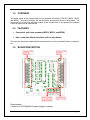
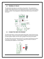
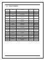
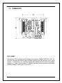
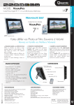
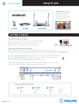
USER’S MANUAL C22 – PENDANT INTERFACE BOARD Rev. 4 JANUARY 2015 USER'S MANUAL TABLE OF CONTENTS Page # Contents 1.0 OVERVIEW ..................................................................................................................... 1 2.0 FEATURES ..................................................................................................................... 1 3.0 BOARD DESCRIPTION .................................................................................................. 1 4.0 TERMINAL OF RELAY ................................................................................................... 2 5.0 CONNECTOR DB25 FOR PENDANT ............................................................................. 2 6.0 PINOUT PENDANT......................................................................................................... 3 7.0 DIMENSIONS.................................................................................................................. 4 User’s Manual Page i 1.0 OVERVIEW This board serves as an interface board for the pendants provided by CNC4PC (MPG2, MPG3, and MPG4). The board conditions the signals (buffer) and provides power to the pendant. The board also has a relay that reflects the status of the e-stop button on the pendant so hardware e-stop functions can be implemented. 2.0 FEATURES Connects 4 and 6 axis pendants (MPG2, MPG3, and MPG4) Has a relay that reflects the status of the e-stop button. This relay can be used to enable/disable external devices, such as breakout boards, contactors, etc... 3.0 BOARD DESCRIPTION Requirements: It requires a +5VDC@100mA power supply to operate. User’s Manual Page 1 4.0 TERMINAL OF RELAY The relay reflects the status of e-stop button on the pendant. The e-stop button is normally closed, when the button is not depressed the circuit is closed and the relay is activated. That activation can be used to keep other hardware active, such as breakout boards, contactors, or an arrangement of relay switches that can govern the safety of the system. 5.0 CONNECTOR DB25 FOR PENDANT The board comes with a connector that receives the pendant. A brain file that runs the brain is provided. Please note that the brain file is different from the brain file provided for other expansion boards, since the one is configured to the wiring of this board. The idea is that you should not use and the PC as a means of deactivating the system in the event of an emergency. The board has a relay can be used as a means to activate/deactivate hardware in a direct manner. User’s Manual Page 2 6.0 PINOUT PENDANT DB25 PENDANT Color Function PC DB25 CONECTOR MACH3 FUNCTION 1 2 3 4 Red Black Green White 2 3 MPG1-A MPG1-B 20 purple +5V MPG GND MPG A signal MPG B Signal MPG A’(when line drive circuit output available) 21 Purple/black B’ (when line drive circuit output available) 5 6 7 8 9 10 18 Green/black White/black Yellow Yellow/black Brown Brown/black Pink +5V LED + GND LED X Axis select Y Axis select Z Axis select 4 Axis select 5(when select the 5th axis) 19 11 12 13 14 15 16 17 Shield Pink/black Gray Gray/black Orange Orange/black Light blue Light Blue/black Red/black 6(when select the 6th axis) X 1 Select X10 Select X100 Select COM of scale select and Axis select E stop C E stop CN N.C, reserve for future use Shield wire User’s Manual 1 4 5 6 7 12 13 8 9 10 OEM Trig #1 OEM Trig #2 OEM Trig #3 OEM Trig #4 OEM Trig #9 OEM Trig #10 OEM Trig #5 OEM Trig #6 OEM Trig #7 15 OEM Trig #8 11 Page 3 7.0 DIMENSIONS DISCLAIMER Use caution. CNC machines can be dangerous machines. Neither DUNCAN USA, LLC nor Arturo Duncan are liable for any accidents resulting from the improper use of these devices. This board is not a fail-safe device and it should not be used in life support systems or in other devices where its failure or possible erratic operation could cause property damage, bodily injury or loss of life. User’s Manual Page 4