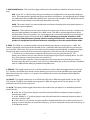
1
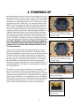
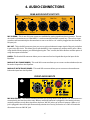
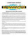
UTA
UnderToneAudio
MPEQ-1 User Manual Version 1.0
1. INTRODUCTION2
2. POWERING UP4
3. RACK MOUNTING5
4. AUDIO CONNECTIONS6
5. FRONT PANEL CONTROLS7
6. THE EQUALIZER
The Filters11
The 4 Parametric Bands14
Series Vs. Parallel18
Notch Mode19
Coming Soon:
7. PRESET SETTINGS
Neve
API
SSL
HELIOS
8. MAINTENANCE
9. SPECIFICATIONS
1
1. INTRODUCTION
Congratulations! You are the proud owner of the UTA MPEQ-1: one of the most powerful and
musical Class A equalizers ever built as well as a wonderfully flexible, beautiful sounding Class
A Mic Preamp/DI. The MPEQ-1 packs a huge amount of Class A audio power into a single rack
unit. Whether you are tracking or mixing, we are confident you will find the MPEQ-1 to be an
indispensable tool in the music making process.
To get up and running right away with your MPEQ-1, skip to Chapters 2 (Powering Up),
3 (Rack Mounting), and 5 (Front Panel Controls). The most vital information about the
proper installation of the MPEQ-1 in this manual is in Chapter 3 (Rack Mounting). The
rest of the manual contains more detailed information that is not essential for understanding the units basic functionality.
The development of the MPEQ-1 began with the process of building a custom console. The
Equalizer was the single most important element of the design. I needed an EQ that would do
everything all of my other EQs did. It needed to have the musicality of a classic Neve or EMI
but the flexibility of a GML or Orban. Larry Jasper and I worked for years refining the design
that ended up in our consoles and is now available in the MPEQ-1. The equalizer in the MPEQ1 unit is identical to the Equalizer in the channel strips of the UTA consoles.
What’s so special about the EQ? It is the only Parametric Equalizer that utilizes Class A amplifiers for EVERY active gain stage in the EQ. Most “Class A” EQs will use a Class A gain stage
only for the final summing stage. The UTA EQ uses Class A gain stages for all of the integrator
stages, all buffering stages, summing stages... Everything. This offers a level of musicality and
clarity that is not available from any other EQ. The EQ also incorporates features that have
never before been available in a hardware EQ unit – let alone one that is Class A. The ability to
blend between peak and shelf shape EQs, as well as being able to reverse the phase of a portion of the frequency spectrum, are features that just simply have not been available before.
The features took years of experimentation to develop. The first version of the EQ became
unstable with certain combinations of settings. It would literally turn into a synthesizer and
blast +28dB of a distorted square wave out the output. We thought we were sunk and that
I would not be able to have the flexibility I wanted while keeping the circuit stable. Patience
and persistence yielded the answer. It forced us to change to a totally different approach for
tackling the subtractive EQ (when you turn down a frequency). This different approach had
an unintended benefit. We realized that this approach allowed us to add the “Notch” mode
and the Phase manipulation mode.
The original design was simply going to have a peak mode and shelf mode. The challenge
was to figure out what the character or slope of the shelf mode would be. We set up the original prototype with a trim pot to be able to adjust the slope of the shelf shape. As soon as I had
a chance to play with this control, I decided it should exist on the front panel... And thus the
“Shape” control was born! Each band can blend from a peak shape - to a modern shelf shape
- to a vintage shelf shape - and everything in between. The UTA EQ can literally emulate the
shape or slope of any shelf EQ ever created, and it can do an endless number moves that no
other EQ has ever been able to do.
2
After I had been using the EQ for months and months in the first UTA console, I started to realize that there were certain shapes involving combinations of bands, that were being difficult
to create. This was a result of the unique type of “cutting” the EQ does combined with the
parallel architecture of the EQ circuit. When I had multiple bands of EQ cutting close to each
other, the interaction between the bands was much more dramatic than I was expecting. We
decided to make another change to the circuit and have the EQ bands be ordered both in
Series and in Parallel. This ended up adding a whole other aspect of flexibility to the EQ. You
can decide if you want a more parallel type interaction or series type interaction depending
on which bands you choose to use. All of the EQs in my consoles were modified to incorporate this new approach.
These significant discoveries and changes are only a few of the notable moments of endless
hours experimenting, testing, and real world use that has helped refine what we feel is the
best equalizer ever built.
The mic preamp has gone through similar exhaustive testing, recording, and listening tests
to end up with the best possible combination of components and features. The goal with
the mic preamp was to have something that would could give me the vintage musicality I
was used to with a Neve or EMI pre, but also have the option of running the mic pre cleaner
when needed. We came up with a mic pre where in the user can bypass either or both of the
transformers. It offers some useful tonal flexibility that now makes the UTA pre my first pick
for almost every recording situation. We also added a low impedance mode by changing the
strapping of the input transformer that performs extraordinarily well with passive ribbon mics.
It is now the only mic pre I use with all of my ribbon mics.
3
2. POWERING UP
Before powering up the unit, be sure you are plugging in to a properly grounded outlet. Check to make sure the AC operating voltage
on the unit is set to properly match the voltage of your AC outlets.
The options are 110V (appropriate for 110V - 120V range) or 240V
(appropriate for 220V - 240V range). The operating voltage of the
MPEQ-1 can be changed by removing the small tray in the power
entry module. Simply flip around the small PCB inside the tray so
the correct voltage is showing in the window when the tray is re-inserted in the power entry module. When changing the MPEQ-1 to
a different operating voltage, you must also change to the appropriate fuse value to be sure it is either properly protected, or won’t
immediately blow the fuse (see Picture 1 or 2 for appropriate fuse
values). The MPEQ-1 should be set up for the voltage you requested when purchasing the unit, but it is always good to double check.
PLUGGING THE MPEQ-1 INTO A 220V-240V OUTLET WHEN SET
FOR 110V OPERATION WILL LIKELY RESULT IN DAMAGE TO THE
POWER SUPPLY OF THE UNIT AND REQUIRE SENDING IT BACK
TO UTA FOR REPAIR!!!
Once you have confirmed the operating voltage is set correctly,
make sure the power switch is in the “OFF” or “DOWN” position.
Plug the supplied IEC AC power cable into the AC power receptacle
on the back of the unit. Plug the other end into an appropriate
AC outlet. You are now ready to power up the unit. Simply push
the power switch on the front panel to the “ON” or “UP” position.
When the MPEQ-1 is powered you will see the VU meter jump
around for a couple of seconds. This is normal. The illumination of
the VU backlight LED is the indication that the MPEQ-1 is powered
up and ready for use.
The MPEQ-1 is protected by a “slow blow” or time delay fuse. The
fuse can be found mounted in the removable tray (see Picture 3).
There is also a small compartment that holds a spare fuse. We have
included a replacement fuse that is compatible with the voltage requested when the MPEQ-1 was originally purchased. If the MPEQ-1
blows a fuse, It is best to first try to determine what caused the fuse
to fail before installing the spare. Once the cause for failure has
been resolved, install the spare fuse and you are ready to go!
Picture 1
Picture 1 shows the MPEQ-1 set in the
110V mode. This will work for voltages
from 110V - 120V
Picture 2
Picture 2 shows the MPEQ-1 set in the
240V mode. This will work for voltages
from 220V - 240V
Picture 3
Picture 3 shows the fuse tray and the hidden spare fuse housing
Picture 4
Picture 4 shows the PCB
voltage selector
4
3. RACK MOUNTING
As you have seen repeatedly in this manual, the MPEQ-1 is a Class A device. Class A circuitry unavoidably
generates heat. How one chooses to rack-mount these devices can have a significant affect on the ambient
temperature inside the enclosure. We have done everything we can (short of using a fan) to improve the
thermal performance and have put them through “worst case” rack mounting scenarios to make sure that
they will perform reliably under those conditions. We just want to make people aware of how the various
rack mounting options will affect the thermal performance.
THE WORST POSSIBLE WAY TO MOUNT MULTIPLE MPEQ-1S IN A RACK, IS TO STACK THEM ONE ON
TOP OF EACH OTHER. When three MPEQ-1s are stacked on top of each other in a rack, the one in the
middle will maintain an average internal ambient temperature of about 120F˚(49C˚). If you stack 6 of them,
the middle units can get up to 130F˚(54C˚), 8 of them can get over 140F˚(60C˚). The MPEQ-1 is protected
by thermistors. When the units get in the 140F˚(60C˚) range, the thermistors will start to shut down the
various DC voltages. THIS IS VERY IMPORTANT!! IF THE LIGHT IN THE VU METER TURNS OFF AND/OR
THE MPEQ-1 STOPS PASSING AUDIO WHILE THE POWER SWITCH IS TURNED ON, THAT MEANS THAT
A THERMISTOR HAS TRIPPED BECAUSE THE UNIT IS RUNNING TOO HOT!! Simply turn off the MPEQ-1,
change the rack mounting situation such that it allows the unit to run cooler and then power it back up.
Everything should be fine. The thermistors will reset themselves after the unit cools down and if the new
rack mounting arrangement keeps things cool enough, it will not happen again. The temperature at which
components inside the unit would start to actually burn up is around 220F˚(105C˚). We are a long ways
away from that, but here is the catch. The closer you get to that temperature, the shorter life span the internal components will have.
WE STRONGLY RECOMMEND LEAVING A GAP BETWEEN EACH MPEQ-1 MOUNTED IN A RACK. If you
mount the MPEQ-1 with even just a 1/3 of a rack space between each unit, the average internal ambient
temperature will be 105F˚- 115F˚(41C˚- 46C˚). An MPEQ-1 sitting by itself in a rack will maintain an average internal temperature of about 100F˚(38C˚). Here is the crazy thing, if you mount an MPEQ-1 vertically,
the average internal temperature drops as low as 80F˚(27C˚)!!! It turns out that the standard the world has
chosen for orienting rack mount equipment (horizontally) SUCKS for thermal dissipation. If you have the
option of mounting the MPEQ-1 vertically it is unquestionably the best way to do it (It is also best for pretty
much all rack mount gear).
At the end of the day, keeping the internal temperature of the MPEQ-1 lower will most likely give it a longer
life span. How much longer? Well, we are not really sure. We expect the MPEQ-1 to function without any
need for service for around 15 years. Will stacking these on top of each other in a rack shave off 1, 2 or 3
years from that expectation? We just won’t know for sure for about 10-15 years from now. We recommend
mounting the units in a way that will keep them as cool as possible, whenever possible.
5
4. AUDIO CONNECTIONS
REAR AUDIO INPUTS/OUTPUTS
Fig. 1
Main Out
s
Line In
Mic Out
Mic In
gain
Chassis
Gnd
With
Transformer
No
Transformer
MIC IN (REAR) - This is one of 2 input connectors available for getting signal into the mic preamp. The rear
mic input is convenient to use if the MPEQ-1 is rack mounted and wired to a patch bay. The rear mic input
connector will automatically be disconnected as soon as an XLR or 1/4” cable is plugged into the front Mic/
DI input jack.
MIC OUT - This male XLR connector gives you access to the unbalanced output signal of the mic pre before
it goes to the EQ circuit. This allows you to split the MPEQ-1 into separate mic preamp and EQ units. When
using the Mic Preamp output, you will be bypassing the “Trim” control, the Phase Reverse and the option of
using the output transformer.
LINE IN - This female XLR connector allows you to connect a line level signal directly to the input of the
Equalizer.
MAIN OUT (NO TRANSFORMER) - This male XLR connector allows you to connect to the unbalanced, transformerless output from the Equalizer.
MAIN OUT (WITH TRANSFORMER) - This male XLR connector allows you to connect to the transformer
balanced output form the Equalizer.
FRONT AUDIO INPUTS
-2
+8
180
-45 -40
-35
-30 -25
-60 -55
0
TRIM
-6 -8
MIC
GAIN
-50
+2
I
EQ
O
OFF
-4
SEP
PH
+6 +4
EQ
0
48V
50Ω
200Ω
-20
MIC
+1
0
-15
n 2 Hot”.
chassis
Lift
-10
0dB)
ed +4 dBu
d +4 dBu
-20
OFF
Xfrmrless
MIC/DI IN (FRONT) - This Neutrik combo jack allows you to plug either a male XLR or a 1/4” instrument connector directly into the front of the unit. When a male XLR connector is plugged in, the combo jack automatically switches to only allow signal from the front “MIC IN” jack to go to the mic preamp. When a 1/4”
jack is plugged in the combo jack automatically switches the circuitry to function as a Class A DI and also
disconnects the rear “MIC IN” jack.
6
5. FRONT PANEL CONTROLS
13 14
2
4
8
16
17
9 10
18
Fig. 2
2K
30
2
1.5K
Q
2K
4K
60
3
4
4K
51
0
1K
2
2
2
3
0
490
3
3
5
4
4
6
7
6
5
120
+6 +4
+8
4
2.2K
7
12
0
5
24
6
30
HF
O
HP
LP
UTA
8.3K
7
60
5
-10
+1
0
-60 -55
6
C
16
K
B
N
I
1.5K
22K
12
Q
24
0
N
-20
5 6 7
-15
11
400
O
16
K
C
340
HMF
B
I
20
22K
N
Q
I
O
8
90
SHAPE
0
9
LMF
O
4.3
K
C
1
10
O
I
6K
N
B
SHAPE
0
8
Xfrmrless
Q
1
9
OFF
20
I
94
0
-20
LF
24
0
C
200Ω
SHAPE
0
K
1.4
B
50Ω
340
48V
1
O
8
0
I
10
OFF
SHAPE
0
8
O
1
9
EQ
10
I
7
TRIM
9
3
-2
10
-30 -25
1
0
-6 -8
-45 -40
-35
-50
180
+2
-4
SEP
PH
MIC
GAIN
120
EQ
8.3K
MIC
MPEQ -1
15
DESCRIPTION OF FRONT PANEL CONTROLS
1. FRONT MIC AND DI INPUT - This combo jack input allows you to plug either a microphone cable
or 1/4” instrument cable directly into the front of the unit. Plugging a mic cable into the front mic
input automatically disables the rear mic input. Plugging in a 1/4” instrument cable allows you to use
the MPEQ-1 as a DI. When a 1/4” cable is plugged in, both the front and rear mic inputs are disabled.
2. MIC->EQ vs. SEP - When this toggle switch is in the up or “MIC->EQ” position, the signal from the
mic pre will be sent directly to the input of the EQ. When in this mode, the “Line In” input on the rear
is disabled. When this toggle switch is in the down or “SEP” (meaning “separate”) position, The mic
pre and equalizer can be used as two separate units. The mic pre and DI can be used individually via
the front or rear mic inputs with the rear “Mic Out” jack. The EQ can be used individually via the “Line
In” jack on the rear panel with one of the 2 “Main Out” jacks. NOTE: The output transformer is ONLY
available on the main output. The “Mic Out” jack is always transformerless.
3. MIC GAIN - This rotary switch allows you to adjust the amount of gain on the mic pre from -10dB to
-60dB in 5dB steps.
4. PHASE - This toggle switch allows you to reverse the polarity of the signal coming into the Equalizer “Line In”. Phase is normal when in the up or “PH” position. Phase is reversed when in the down
or “180” position. When in the “MIC->EQ” mode, it allows you to reverse phase on the mic pre signal.
NOTE: You will not be able to reverse the phase of the mic pre signal if it is being used separate from
the equalizer.
5. PAD - This toggle switch engages the passive -20dB pad before the mic pre. There is no padding
when the switch is in the up or “0” position. -20dB of padding is added when the switch is in the
down or “-20” position.
6. 48V - This toggle switch turns on or off the 48V “phantom power”. Turn this on when using microphones that require “phantom power” to function. Turning the 48V “phantom power” on or off can
cause a very loud low frequency “thump” to come out of the mic pre. Make sure you turn down your
monitors or headphones when changing the 48V setting. NOTE: Some ribbon microphones can be
damaged by “phantom power”. It is always best to turn off the phantom power before plugging
in any type of passive ribbon mic.
7
7. 50Ω/200Ω/Xfrmrless - This 3 position toggle switch selects the transformer mode for the input of mic preamp.
50Ω - In the “UP” or “50Ω” position, the input transformer is configured for a low impedance high gain
input. This setting works especially well for passive ribbon microphones. You will typically get an added
3 or 4 dB of gain with no additional amplifier noise. It also has sonic benefits as well. We have found the
ribbon mics to sound clearer, more balanced, and solid in this mode.
200Ω - This mode is best if you want to add input transformer coloration while using either dynamic or
condenser type microphones.
Xfrmrless - This mode removes the input transformer from the input of the mic preamp. It will give you
the same input impedance and gain as the “200Ω” mode. This offers a unique opportunity to hear a
transformerless Class A mic preamp. It is a stunningly pristine sound and is ideal for any recording that
needs the highest degree of clarity and detail. NOTE: switching to or from the “Xfrmrless” mode
will cause a loud low frequency thump (similar to turning the 48V on/off). Be sure you have your
speakers or headphones turned down whenever switching to or from the transformerless mode.
8. TRIM - The “TRIM” is a constantly variable control that allows you to boost or cut the signal +/-10dB. This
control is specifically on the input of the Equalizer circuit. It will ONLY affect the level of the mic pre when you
are in the “MIC->EQ” mode. The mic pre has no fine trim of level when used individually. In addition to simply
having a fine adjust of the level, there are two other applications of the fine trim that can be very helpful:
1) The fine trim can be used to turn down the level from the mic pre going into the EQ. This allows you to drive the mic pre more without over driving the input of your recording device. The UTA
Class A mic preamp sounds great when you overdrive it!
2) The fine trim gain stage has a unique configuration that causes the noise from this gain stage to
decrease when the gain is turned up. You can use it to add 10dB of gain to the mic preamp (a combined
total of +70dB) without adding any additional amplifier noise.
9. TRIM I/O - This toggle switch turns on or off the variable trim control. When the toggle switch is in the “Up”
or “I” position, the variable trim control is active allowing you to boost or cut the equalizer input signal 10dB.
When the switch is in the “down” or “O” position, the variable trim control is deactivated and the equalizer
input gain is unity.
10. EQ/OFF - This toggle switch turns on or off the entire EQ circuit. When the toggle switch is in the “Up” or
“EQ” position, The EQ circuit is added to the signal path. When the toggle switch is in the “Down” or “ OFF”
position the entire EQ circuit is bypassed.
11. B/C/N - This three position toggle switch selects the mode for the gain adjust on an individual parametric
band of the EQ.
B - In the “Up” or “B” position, the gain control for that band will boost whatever frequency/shape is
selected up to 15dB.
C - In the “Middle” or “C” position, the gain control for that band will cut whatever frequency/shape is
selected as much as 15dB.
N - In the “Down” or “N” position, the gain control for that band will allow you to either notch out a frequency or reverse the phase of a particular frequency. (For more information on the notch mode see pg. 19
in The Equalizer section)
8
12. FREQUENCY/Q CONTROL (PARAMETRIC BAND) - This dual concentric potentiometer allows you
to select the frequency being adjusted and the “Q” or “Bandwidth” of the adjustment being made.
The Upper Knob controls the “Q” or “Bandwidth”. In the fully counter-clockwise position, you
get the widest “Q” of .3. As the knob is turned clockwise the “Q” will get more narrow. In the
fully clockwise position you get the most narrow “Q” of 10.
The Lower Knob controls the frequency selection. The frequency gets lower as the knob is
turned counter-clockwise and conversely, will get higher as the knob is turned clockwise.
13. GAIN/SHAPE - This dual concentric potentiometer controls both the amount of gain adjust and
the shape of the adjustment.
The Upper Knob controls the shape. In the fully counter-clockwise position, the EQ band will
boost or cut a “bell” or “peak” type shape. As the knob is turned clockwise, the shape progressively turns into a shelf shape. The 12 o’clock position achieves a conventional shelf shape. Past
the 12 o’clock position, you can change the slope of the shelf.
The Lower Knob controls the amount of gain adjust. When the B/C/N toggle switch (see item
11 in section 4) is in the “B” or “C” modes you can boost or cut 15dB of the selected frequency.
(Certain shelf/Q combinations will allow as much as 30dB of boost or cut).
When the B/C/N toggle switch is in the “N” position, the gain control will allow you to either
notch the selected frequency or reverse the phase of the selected frequency. To notch the selected frequency, set the gain control to “5”. To reverse phase of the selected frequency, set the
gain control to “10”. (See section 6 “The Equalizer” for more information on the Notch mode).
14. EQ BAND I/O - This toggle switch turns on or off an individual band of the equalizer. When the
toggle switch is in the “up” or “I” position, the EQ band will be engaged. When the toggle switch is in
the “down” or “O” position, the EQ band circuitry will be bypassed.
15. FREQUENCY/Q (FILTERS) - These dual concentric potentiometers allow you to adjust the frequency and the “Q” of the HP/LP filters.
The Upper Knob controls the “Q”. In the fully counter-clockwise position, the filter will have the
most gradual roll off. As the knob is turned clockwise the “Q” will get progressively steeper. At
the 12 o’clock position, you will get the steepest possible roll off (about 12dB per octave) without boosting the selected frequency. As the “Q” control is turned clockwise past the 12 O’clock
position, The frequency selected will begin to be boosted. In the fully clockwise position there
will be 10dB of boost at the selected frequency and the slope of the roll off averages out to
around 18dB per octave.
The Lower Knob controls the frequency selection. The frequency gets lower as the knob is
turned counter-clockwise and conversely, will get higher as the knob is turned clockwise. On
the skirt of the knob, you will see a scale showing the range of frequency corresponding to a
particular setting.
9
16. FILTER I/O - This toggle switch turns on or off an individual filter band. When the toggle switch is in the
“Up” or “I” position, the filter band is active. When the switch is in the “down” or “O” position, the filter band
will be bypassed.
17. VU METER - This is a VU meter that will show the level present at the input of the EQ circuit.
When the MPEQ-1 is in the “MIC->EQ” mode, the VU will show the level of the signal coming from
the Mic Preamp. In the “SEP” mode the VU will show the level of signal connected to the “Line In”. In
either case, the VU will reflect any adjustments made with the “Trim” control. The VU does NOT show
the resulting level caused by any EQ cutting or boosting.
(We felt it was best to have the VU function the way a VU does on a console channel strip, Where the
VU specifically shows the level at the input of the channel strip and does not show any level changes
caused by EQ adjustments. The level resulting from EQ changes can be seen with the metering of the
recording device being used. If you would prefer to have the VU show the final output level including
any level changes caused by EQ adjustments, there is a relatively easy modification that can make
that happen.)
18. POWER SWITCH - This switch turns on or off the power for the MPEQ-1. In the up position, the
power is turned on. In the down position, the MPEQ-1 will be powered off. The LED lighting in the
VU can be used as an indication weather or not the MPEQ-1 is on or off.
10
6. THE EQUALIZER
In this section we will take a very in depth look at the functions of the UTA EQ. If you want a quick over view of the
EQ functions, see Section 4 (Front Panel Controls).
There are far too many possible combinations of settings and curves that can be created by the MPEQ-1 to be able
to show graphs of all of them. We will only be showing graphs of settings with a frequency selection of 1.5K and
in either LP or High Shelf modes. The HP, Low Shelf, or “Cut” counter parts will look like a mirror image version of
what is shown in these graphs.
Similar to many modern equalizers, the MPEQ-1 has both “High Pass” and “Low Pass” filters. The terms “High
Pass” and “Low Pass” can be a bit confusing. “High Pass Filter” is referring to the REMOVAL of LOW frequencies below a selected frequency, or in a more technical sense, the filter is allowing the higher frequencies to
“Pass” through the circuit while blocking or filtering the lower frequencies. Conversely, “Low Pass Filter” refers
to the REMOVAL of HIGH frequencies while letting the frequencies below a selected frequency “Pass” through
the circuit.
The thing that is unique about the LP/HP filters on the UTA EQ is the addition of an active “Q” control. This
“Q” control allows you to change the slope of the roll off, as well as being able to actually create a boost or
resonance at the frequency selected. It is important to understand that an active “Q” control is different than
stacking filters to create steeper roll offs. The filters in the circuit are always 12dB/octave. The “Q” control is
changing how aggressively the filter is applied. When the “Q” is in the fully counter-clockwise position, the
filter will ease into the 12dB/octave roll-off.
Fig. 3
Gradual introduction of Roll Off
Selected frequency of roll off (1.5K)
EXAMPLE OF ROLL OFF WITH LOW PASS FILTER SET
AT 1.4K WITH FULLY COUNTER CLOCKWISE “Q”
Roll Off finally achieves a
12dB/Octave slope
You can clearly see the gradual introduction of roll off much lower than the frequency selected. This setting is
great when you want to gently roll off high or low frequencies in a way that sounds very natural. The gradual
non-linear slope minimizes phasing anomalies and almost eliminates any resonance or “ringing” introduced
by the filter. Also notice that there is a significant amount of roll off at the frequency selected. The frequency
is set at 1.5K and the roll off is already almost 10dB down at that frequency. The lower “Q” settings will cause
a greater amount of filtering because the filtering starts before the selected frequency.
11
Fig. 4
Selected frequency of roll off (1.5K)
Roll Off quickly transitions to a
12dB/Octave slope
EXAMPLE OF ROLL OFF WITH LOW PASS FILTER SET
AT 1.5K WITH “Q” AROUND THE 12 O’CLOCK POSITION
Fig. 4 illustrates how increasing the “Q” setting doesn’t actually change the dB/octave value, but changes
how quickly the roll off transitions into the 12dB/octave roll off. The roll off initiates much closer to the
selected frequency and quickly achieves a linear 12dB/octave slope. This sounds much more similar to a
conventional 12dB/octave filter.
Fig. 5
10dB boost at the selected frequency of 1.5K
EXAMPLE OF ROLL OFF WITH LOW PASS FILTER SET
AT 1.5K WITH “Q” IN THE FULLY CLOCKWISE POSITION
Roll Off settles back to a
12dB/Octave slope
12
Fig. 5 illustrates the boost or resonance created with the higher “Q” settings. These higher “Q”
settings can be great for creating filtering effects. You will really hear the ringing of the filter.
You can create very effected “telephone” type lo-fi effects, or use it to do more musical, natural
sounding filters as well. One of my favorite applications is with the low end -Using the high
pass filter to boost low end is a very punchy sound; It can help focus the low end of an instrument to emphasize the natural resonance of the frequency range it is occupying.
It is really effective for kick drums; It removes any sub frequencies below the punchy part of the
drums sound and focuses all of the energy in a place that will cut through a mix better without
eating up headroom.
I also really like it for guitar. Many times, guitars will have rumbling noise below the range
of notes that are actually being played. I have found with conventional High Pass Filters, the
sound would get too thin when I rolled off at the point of the lowest note being played. With
the “Q” control on the MPEQ-1 High Pass Filter, I can roll off at the lowest frequency, then restore
the natural body to the sound by adding a boost or resonance at the lowest frequency that the
instrument is playing.
Fig. 6
LP FILTER SET AT 1.4K WITH VARIETY OF “Q” SETTINGS
Lowest “Q” setting (fully counter-clockwise)
“Q” in the 8 O’Clock-ish position
“Q” in the 10 O’Clock-ish position
“Q” in the 12 O’Clock position
“Q” in the 2 O’Clock-ish position
“Q” in the 4 O’Clock-ish position
Highest “Q” setting (fully clockwise)
EXAMPLE OF ROLL OFF WITH LOW PASS FILTER SET
AT 1.5K WITH PREGRESSIVELY HIGHER “Q” SETTINGS
Fig. 6 allows you to better see how the slope and peaking develop as the “Q” control goes from
the fully counter-clockwise position to the fully clockwise position.
13
THE 4 PARAMETRIC BANDS
The 4 parametric bands have 2 configurations. The HF and HMF bands can blend between a
peak shape and a “High Shelf”. The LMF and LF bands can blend between a peak shape and a
“Low Shelf”. The bands are also broken into two parallel groups that are then in series. Each
band can be set to boost, cut, notch or manipulate phase. All of these variables combined create a staggering amount of flexibility and control over the shapes and curves the equalizer is
capable of generating. We will try to cover as many of these combinations as possible.
THE “SHAPE” CONTROL
The shape control is blending between a peak or bell type shape and a shelf shape. When the
knob is all the way counter-clockwise, it is a peak or bell shape. As the knob is turned clockwise, it turns progressively more into a shelf shape. In Fig. 7, you see how the peak or bell shape
gradually transforms into a conventional shelf shape as you turn the shape control from the
fully counter-clockwise position to the 12 o’clock position. Notice the HF band graphics that
will show the exact setting combinations used to create each curve.
Fig. 7
SHAPE
I
O
6
2
7
1
8
0
10 9
5
HF
1.5K
4
3
2K
4K
K
8.3K
SHAPE
I
O
6
2
7
1
8
0
10 9
5
HF
1.5K
4
3
2K
K
4K
16
C
Q
22K
B
N
8.3K
SHAPE
I
O
6
2
7
1
8
0
10 9
5
HF
1.5K
4
3
2K
K
4K
16
C
Q
22K
B
N
8.3K
SHAPE
I
O
6
2
7
1
8
0
10 9
HF
1.5K
5
4
3
2K
K
4K
16
8.3K
C
Q
22K
B
N
16
C
Q
22K
B
N
The green curve is a good example of how you can open up the top end a little when you’re
doing a mid range boost. The yellow curve shows a conventional shelf shape where the boost
starts to rise below the frequency selected, reaches its maximum amount of boost at the frequency selected and then stays up above the frequency selected.
14
In Fig. 8, You can see what happens as you continue to turn the shape control past the 12 o’clock
position. This is the range of the shape control where you can actually change the slop or contour of the shelf. This allows you to emulate the shelf EQ of pretty much any other shelf EQ ever
made.
Fig. 8
SHAPE
I
O
6
2
7
1
8
0
10 9
5
HF
1.5K
4
3
2K
4K
K
8.3K
SHAPE
I
O
6
2
7
1
8
0
10 9
5
HF
1.5K
4
3
2K
K
4K
16
C
Q
22K
B
N
8.3K
SHAPE
I
O
6
2
7
1
8
0
10 9
5
HF
1.5K
4
3
2K
N
K
4K
16
C
Q
22K
B
8.3K
SHAPE
I
O
6
2
7
1
8
0
10 9
HF
1.5K
5
4
3
2K
K
4K
16
8.3K
C
Q
22K
B
N
16
C
Q
22K
B
N
The green curve is a really useful shape. Because of the very linear, gradual rise of the boost, it
minimizes phase anomalies and sounds extraordinarily natural. Use that shape if you want a
sound to be brighter without sounding EQ’d at all. The blue curve is an example of a more “classic” type shelf shape with an under shoot and the beginning of it. You will see that curve on
old 80 series Neve EQs. It is also important to note that, as the shape control goes past the 12
o’clock position, the frequency range being boosted will seem to get higher. The frequency selection is not changing, it is a result of the higher frequencies being emphasized more because
of the change in the slope of the boost.
15
In Fig. 9 We will look at what happens when you start to combine the “Q” control with a shelf
shape.
Fig. 9
SHAPE
I
O
6
2
7
1
8
0
10 9
5
HF
1.5K
4
3
2K
4K
K
8.3K
SHAPE
I
O
6
2
7
1
8
0
10 9
5
HF
1.5K
4
3
2K
N
K
4K
16
C
Q
22K
B
8.3K
SHAPE
I
O
6
2
7
1
8
0
10 9
5
HF
1.5K
4
3
2K
K
4K
16
C
Q
22K
B
N
8.3K
SHAPE
I
O
6
2
7
1
8
0
10 9
5
HF
1.5K
4
3
2K
K
4K
16
C
Q
22K
B
N
8.3K
SHAPE
I
O
6
2
7
1
8
0
10 9
5
HF
1.5K
4
3
2K
K
4K
16
C
Q
22K
B
N
8.3K
SHAPE
I
O
6
2
7
1
8
0
10 9
5
HF
1.5K
4
3
2K
K
4K
16
C
Q
22K
B
N
8.3K
SHAPE
I
O
6
2
7
1
8
0
10 9
HF
1.5K
5
4
3
2K
K
4K
16
8.3K
C
Q
22K
B
N
16
C
Q
22K
B
N
The curves in this graph show what happens when you progressively increase the Q (starting
fully counter-clockwise and turning the knob clockwise) of a conventional shelf shape. You can
see how a peak starts to develop on top of the initial shelf shape as the rise of the shelf gets
steeper. Once you get past the 12 o’clock position, an “under shoot” starts to develop. The under shoot is the dip that you see before the rise. This combination of the shelf shape with the Q
control can achieve a huge amount of boost. Notice that when the Q control is fully clockwise,
there is more than 30dB of boost happening at the selected frequency. BE CAREFUL!!! BOOSTING 30dB OF A FREQUENCY WHEN YOUR SPEAKERS ARE TURNED UP LOUD CAN RESULT IN
SPEAKER AND/OR EAR DAMAGE.
The thing that is really useful about these combinations of shelf and Q, is that you can achieve
curves that would normally take 3 bands of an equalizer to do and when these more complex
curves are created with a single filter, there is an inherent musicality to it. It minimizes the compounding of phasing anomalies you get when creating a curve like this with multiple bands.
The end result sounds more natural or organic to the original sound.
I like using these combinations to move the energy in a sound from one area of the frequency
spectrum to another in a more organic way. For example, if I have a bass guitar that needs to
sound deeper, I can (with one band) boost frequencies below 100hz and simultaneously be
reducing some of the frequencies just above 100hz. The bass just sounds deeper without really
sounding EQ’d. In the high end frequencies, it is really great for adding a pointed sort of ring to
a shelf boost that will give the instrument a more identifiable character. This slight “ringing” in
the boost will help it stand out from other elements in the mix.
16
In Fig.10 We will look at the range of widths available by adjusting the Q control with the shape
control in the peak or fully counter-clockwise position.
Fig. 10
SHAPE
I
O
6
2
7
1
8
0
10 9
5
HF
1.5K
4
3
2K
4K
K
8.3K
SHAPE
I
O
6
2
7
1
8
0
10 9
5
HF
1.5K
4
3
2K
N
K
4K
16
C
Q
22K
B
8.3K
SHAPE
I
O
6
2
7
1
8
0
10 9
5
HF
1.5K
4
3
2K
K
4K
16
C
Q
22K
B
N
8.3K
SHAPE
I
O
6
2
7
1
8
0
10 9
5
HF
1.5K
4
3
2K
N
K
4K
16
C
Q
22K
B
8.3K
SHAPE
I
O
6
2
7
1
8
0
10 9
5
HF
1.5K
4
3
2K
K
4K
16
C
Q
22K
B
N
8.3K
SHAPE
I
O
6
2
7
1
8
0
10 9
5
HF
1.5K
4
3
2K
N
K
4K
16
C
Q
22K
B
8.3K
SHAPE
I
O
6
2
7
1
8
0
10 9
HF
1.5K
5
4
3
2K
K
4K
16
8.3K
C
Q
22K
B
N
16
C
Q
22K
B
N
The curves in this graph shows what happens when you have the shape control in the peak
(fully counter clockwise position) while turning the Q control clockwise starting from the fully
counter-clockwise position. The lowest setting achieves a very wide Q of about .3. The highest
setting or fully clockwise position achieves a very narrow Q of about 10.
The wider settings are good for making overall tonal changes to a sound. You can boost or cut
a broad section of frequencies to make a sound generally brighter or “bassier”. The more narrow settings are excellent for addressing a specific frequency. If there is an offending overtone
in a guitar track, you can surgically remove it without changing the overall tonal balance of the
sound.
17
SERIES VS. PARALLEL
There are two main ways the filters in an equalizer circuit will interact - either a series type interaction or
a parallel type interaction. When using multiple bands of an equalizer, the different interactions can be
dramatic. Here is a list showing the interactive behavior of some familiar equalizers we measured.
SERIES
BOTH
PARALLEL
SSL (all versions)
Neve 88R
Orban 672
UTA
GML
Quad 8
Fig. 11
3.5K difference
The green curve was created by boosting 1.2K 12 dB with the HMF band and boosting 12K
12dB with the HF band. On the MPEQ-1 the HMF and HF bands are in SERIES.
The blue curve was created by boosting 1.2K 12 dB with the LMF band and boosting 12K
12dB with the HF band. On the MPEQ-1 the LMF and HF bands are in PARALLEL.
You can see the dramatic difference in how the two separate boosts add up in the area where they overlap. At 3.5K, there is a 4dB difference in the resulting curves and, as you could imagine, they sound very
different. The difference is caused by a difference in the phasing at the intersecting points in the curves.
The series interaction can be described as being more “literal” because the two individual boosts will
add to each other where they overlap. The parallel interaction can be described as being more “natural”
because, if you had a room that was acoustically causing these exact two individual boosts (12dB at 1.2K
+ 12dB at 12K) the resulting curve would look like the parallel version.
18
NOTCH MODE
There are 2 functions made available by the Notch Mode; Notch Filtering and Phase Adjust.
1) NOTCH FILTERING
First we will look at the Notch Filtering. The Notch filtering works similarly to the “Cut” mode. The EQ
circuit is simply filtering the original signal, reversing the phase of it and then blending it with the original signal. When the phase reversed, filtered signal is blended back in with the original, it will start to
cancel those frequencies isolated by the filter. The “CUT” mode is set up such that it will only cancel the
selected frequency by a maximum of 15dB. In “Notch Mode” the gain structure is adjusted to allow you
to completely cancel out the selected frequency. This cancelling out of the selected frequency occurs
when the gain control is set to “5”.
Fig. 12
5
SHAPE
I
4
O
1
9
2
8
3
7
6
HMF
0
1K
2.2K
10
0
N
6K
5
SHAPE
I
4
O
1
9
2
8
3
7
6
HMF
0
10
2.2K
1K
Q
0
40
4.3K
0
C
51
B
N
6K
5
SHAPE
I
4
O
1
9
2
8
3
7
6
HMF
0
10
2.2K
1K
Q
0
N
40
4.3K
0
C
51
B
6K
5
SHAPE
I
4
O
1
9
2
8
3
7
6
HMF
0
10
2.2K
1K
Q
0
40
4.3K
0
C
51
B
N
6K
5
SHAPE
I
4
O
1
9
2
8
3
7
6
HMF
0
10
2.2K
1K
Q
0
N
40
4.3K
0
C
51
B
6K
5
SHAPE
I
4
O
1
9
2
8
3
7
6
HMF
0
10
2.2K
1K
Q
0
40
4.3K
0
C
51
B
N
6K
5
SHAPE
I
4
O
1
9
2
8
3
7
6
HMF
0
10
2.2K
1K
Q
0
40
4.3K
0
6K
C
51
B
N
Q
40
4.3K
C
0
51
B
As you can see in fig. 12, the Notch Mode allows you to achieve an enormous amount of cut. Our test
equipment is measuring over 50dB of reduction at the selected frequency. With the Q control you can
adjust how wide the notch is. In theory, the amount of cut stays the same as the Q gets narrower, but
the graphs do not have the resolution to show this. Notch filtering is very useful for eliminating an offending frequency. You can use it to remove a 60hz hum or the hi whining sound of a computer fan or
disk drive.
The shape control also stays active when in Notch Mode. With the shape control in the 12 O’clock position, the Notch Mode will make parametric bands function like HP/LP filters. The LF and LMF bands will
turn into HP (High Pass) filters. The HMF and HF bands will turn into LP (Low Pass) filters. This can allow
you to do some more extreme filter effects.
2) PHASE ADJUST
The Phase Adjust function is achieved by turning the gain control to “10” (fully clockwise) while the EQ
band mode switch is in the “N” or “Notch” position. Both the “Shape” and “Q” controls stay active and
hugely influence the how the Phase Adjust will perform.
19
The Phase Adjust mode is an extension of the Notch Filter mode. The same filtered, phase reversed signal is being turned up past the null point so it will start to blend back in with the original signal. When
the gain control is at the “10” or fully clockwise position the filtered, phase reversed signal is then at
unity gain with the original signal. What you have done at that point, is reversed the phase of a portion of the frequency spectrum. With the right shape/Q settings, it can be done without changing the
frequency response of the original sound at all.
Fig. 13
I
O
1
6
2
7
HMF
5
4
3
2.2K
1K
Q
40
4.3K
0
0
6K
C
51
B
N
SHAPE
8
0
10 9
0˚
15˚
30˚
60˚
90˚
120˚
150˚
180˚
150˚
90˚
120˚
60˚
30˚
15˚
0˚
The graph in fig. 13 is optimized to illustrate what is happening and is not intended to be a technical
representation of the function. The red line across the top is showing the actual frequency response of
the processed signal. You can see that it is still pretty much flat across and that means that the sound by
itself does not sound any different. The green line is showing the width of the phase adjustment being
made. The greyed area is showing the portion of frequencies that are being affected by the phase adjustment. The dashed light blue lines are showing the degree of phase shift as you travel away from the
selected frequency in both directions.
With this example, all of the information in the original sound at the 1K frequency has been phase
reversed 180˚. The degree of phase reversal then starts to travel back to 0˚ as you move away from the
1K frequency range. For example you can see that there is a 90˚ phase shift both below the 1K selected
frequency (at about 530hz) and above (at about 1.9Khz). This is how you can achieve a varying degree of
phase shift in a specific frequency range.
Why would you want to do this? Well, initially we weren’t really sure. Larry had realized that this was
possible with the unique approach to subtractive EQ we were using, but because this feature had never
really existed before neither of us really had any idea how useful it might be. It turns out that it can be
very useful, in fact, a life saver for certain things.
I have been using it for drums, bass and guitar mostly. Those are instruments that will frequently have
multiple signals capturing a single sound or performance. With drums, whenever you use more than
one microphone there is a phase interaction that can dramatically affect the overall sound. If you are
blending multiple amps or microphones for a guitar sound, the phase interactions hugely influence the
blended sound. It is common to use both an amp and DI signal for electric bass and again the phase
interactions become very important
20
With drums I have been able to correct phasing problems that resulted from poor mic placement.
Sometimes a mic will be placed such that it is 90˚ out of phase with other mics it is blending with. A
traditional 180˚ phase switch can not correct this problem and it will usually require excessive EQ’ing to
make up for the loss body when the signals are blended. With the Phase Adjust feature you can cause
a 90˚ phase shift in the necessary frequency range to correct the problem and preserve a more natural
sounding blend of the mics. There is a more detailed example of this here http://undertoneaudio.com/
eq.html.
On bass, I have had situations where the amp and DI signals are not blending in an optimum way. The 2
sources will either sound punchy but too nasally or deep but not punchy enough. With the deeper version, I can phase reverse a portion of a slightly higher frequency range (around 150hz) to get some more
punch but have enough control to make sure it doesn’t get nasally sounding. This fix can happen without either of the signal being EQ’d or sounding any different than they originally did. It is only changing
how they blend together to achieve the results I want.
On guitars it can be really cool. I like to use multiple amps and sometimes I will use the variable phase
feature to fix a problem or other times I will use it to intentionally cause the different amps to blend in
weird ways to get a unique tonality that will really stand out in a mix or from other guitars. When these
tonal changes are done by manipulating the phase, the results always seem to be more natural sounding. They don’t sound like I forced them there with EQ.
IMPORTANT INFORMATION ABOUT THE SETTINGS!!!
There are 3 settings that will give the best results for adjusting phase. When I use the phase adjust
feature I want it to only affect the phase and not change the frequencies or sound EQ’d at all. There are
settings that will definitely sound EQ’d so this is important.
SETTING NUMBER 1
1
2
K
2.2
K
4.3
K
2.2
K
4.3
K
2.2
K
4.3
0
1
2
3
2.2
K
4
K
4
K
2.2
6K
5
4.3
.3K
0
0
0
1
1
3
6K
5
4
3
2.2
K
3
K
4
4
6K
0
4.3
5
2
2
6K
5
1
3
2
6K
4
6
0
5
1
0
2
40
6K
2.2
K
0
51
K
6
Q
40
0
4.3
7
1K
0
40
C
8
HMF
51
0
51
B
N
O
6
Q
40
0
7
1K
I
8
O
HMF
SHAPE
0
10 9
1K
51
40
0
I
6
0
SETTING NUMBER 3
APE
7
Q
51
40
0
C
8
6
1K
N
0
0
7
0
51
B
Setting 2 will give you a shelf shaped phase reversal. If you are using either the LF or LMF
bands, the 180˚SHAPE
phase
shift at the selected frequency will extend through the frequency
I
range below that point. If you are using either the HF or HMF bands, the 180˚ phase shift at
O
the selected frequency
will
extend through the frequency range above that point. To mainQ
HMF
tain a flat Bfrequency response in this setting the gain control must stay at “10”, the “SHAPE”
C stay at 12 O’clock and the Q control must stay in the fully counter-clockwise
control must
position. NYou can freely change the selected frequency (highlighted in red) without affecting the frequency response.
10 9
O
HMF
1K
40
40
I
8
Q
1K
SHAPE
SHAPE
0
0
SETTING NUMBER 2
10 9
1K
51
51
C
N
Q
6
6
1K
10 9
7
7
O
HMF
SHAPE
8
0
10 9
8
B
Setting 1 will give you a bell shaped phase reversal (see fig. 13) where the selected
I
I
frequency is reversed 180˚
and then the degree of
phase shift will travel back to 0˚
in both directions. YouO can change both the frequency
and Q (highlighted in red)
O
Q
Q
as much as you want
response. The shape control
HMFwithout changing the frequency
HMF
B
B
must stay in theC fully counterclockwise position
and the gain control must stay in
C
the fully clockwise
(gain of “10”) positionN or the frequency response will not remain
N
flat.
3
I
4
SHAPE
5
10 9
Setting 3 will also give you a shelf shaped phase reversal except it will be 0˚ phase
shift at the frequency selected and travel towards 180˚ beyond that point. This setting good for causing a phase shift at the extreme ends of the frequency spectrum.
To maintain a flat frequency response in this setting the gain control must stay at
“10”, the “SHAPE” control must stay fully clockwise and the Q control must stay in
the fully counter-clockwise position. You can freely change the selected frequency
(highlighted in red) without affecting the frequency response.
21
6K