1
Cat. No. V084-E1-01
NT11
Programmable Terminal
USER’S MANUAL
NT11
Programmable Terminal
User’s Manual
Produced January 2004
iv
Notice:
OMRON products are manufactured for use according to proper procedures by a qualified operator
and only for the purposes described in this manual.
The following conventions are used to indicate and classify precautions in this manual. Always heed
the information provided with them. Failure to heed precautions can result in injury to people or damage to property.
!DANGER
Indicates an imminently hazardous situation which, if not avoided, will result in death or
serious injury.
!WARNING
Indicates a potentially hazardous situation which, if not avoided, could result in death or
serious injury.
!Caution
Indicates a potentially hazardous situation which, if not avoided, may result in minor or
moderate injury, or property damage.
OMRON Product References
All OMRON products are capitalized in this manual. The word “Unit” is also capitalized when it refers to
an OMRON product, regardless of whether or not it appears in the proper name of the product.
The abbreviation “Ch,” which appears in some displays and on some OMRON products, often means
“word” and is abbreviated “Wd” in documentation in this sense.
The abbreviation “PLC” means Programmable Controller. “PC” is used, however, in some Programming Device displays to mean Programmable Controller.
“Host” means a personal computer that controls the NT11.
Visual Aids
The following headings appear in the left column of the manual to help you locate different types of
information.
Note Indicates information of particular interest for efficient and convenient operation of the product.
1,2,3...
1. Indicates lists of one sort or another, such as procedures, checklists, etc.
Ó OMRON, 2004
All rights reserved. No part of this publication may be reproduced, stored in a retrieval system, or transmitted, in any form, or
by any means, mechanical, electronic, photocopying, recording, or otherwise, without the prior written permission of
OMRON.
No patent liability is assumed with respect to the use of the information contained herein. Moreover, because OMRON is constantly striving to improve its high-quality products, the information contained in this manual is subject to change without
notice. Every precaution has been taken in the preparation of this manual. Nevertheless, OMRON assumes no responsibility
for errors or omissions. Neither is any liability assumed for damages resulting from the use of the information contained in
this publication.
v
vi
TABLE OF CONTENTS
PRECAUTIONS . . . . . . . . . . . . . . . . . . . . . . . . . . . . . . . . . . .
xi
1
Intended Audience . . . . . . . . . . . . . . . . . . . . . . . . . . . . . . . . . . . . . . . . . . . . . . . . . . . . . . . . .
xii
2
General Precautions . . . . . . . . . . . . . . . . . . . . . . . . . . . . . . . . . . . . . . . . . . . . . . . . . . . . . . . .
xii
3
Safety Precautions . . . . . . . . . . . . . . . . . . . . . . . . . . . . . . . . . . . . . . . . . . . . . . . . . . . . . . . . .
xii
SECTION 1
Functions of the NT11 . . . . . . . . . . . . . . . . . . . . . . . . . . . . . .
1
1-1
Getting Starting . . . . . . . . . . . . . . . . . . . . . . . . . . . . . . . . . . . . . . . . . . . . . . . . . . . . . . . . . . .
2
1-2
Role and Operation of NT11 . . . . . . . . . . . . . . . . . . . . . . . . . . . . . . . . . . . . . . . . . . . . . . . . .
2
1-3
Functions of NT11 . . . . . . . . . . . . . . . . . . . . . . . . . . . . . . . . . . . . . . . . . . . . . . . . . . . . . . . . .
4
1-4
System Configuration . . . . . . . . . . . . . . . . . . . . . . . . . . . . . . . . . . . . . . . . . . . . . . . . . . . . . .
8
1-5
Direct Connection Function. . . . . . . . . . . . . . . . . . . . . . . . . . . . . . . . . . . . . . . . . . . . . . . . . .
9
1-6
Before Operating . . . . . . . . . . . . . . . . . . . . . . . . . . . . . . . . . . . . . . . . . . . . . . . . . . . . . . . . . .
12
SECTION 2
Hardware Settings and Connections. . . . . . . . . . . . . . . . . . .
15
2-1
Description of Parts and Settings. . . . . . . . . . . . . . . . . . . . . . . . . . . . . . . . . . . . . . . . . . . . . .
16
2-2
Installation . . . . . . . . . . . . . . . . . . . . . . . . . . . . . . . . . . . . . . . . . . . . . . . . . . . . . . . . . . . . . . .
19
2-3
Connecting to the NT Support Tool. . . . . . . . . . . . . . . . . . . . . . . . . . . . . . . . . . . . . . . . . . . .
22
2-4
Connection to a PLC by the Host Link (RS-232C Type) . . . . . . . . . . . . . . . . . . . . . . . . . . .
22
2-5
Connection to a PLC by the Host Link (RS-422A Type) . . . . . . . . . . . . . . . . . . . . . . . . . . .
38
2-6
Connection to a PLC by the NT Link (RS-232C Type) . . . . . . . . . . . . . . . . . . . . . . . . . . . .
50
2-7
Connection to a PLC by the NT Link (RS-422A Type) . . . . . . . . . . . . . . . . . . . . . . . . . . . .
55
2-8
Connecting a Printer . . . . . . . . . . . . . . . . . . . . . . . . . . . . . . . . . . . . . . . . . . . . . . . . . . . . . . .
57
SECTION 3
System Menu Operation. . . . . . . . . . . . . . . . . . . . . . . . . . . . .
59
3-1
Operation Flow by the System Menu . . . . . . . . . . . . . . . . . . . . . . . . . . . . . . . . . . . . . . . . . .
60
3-2
Starting the NT11. . . . . . . . . . . . . . . . . . . . . . . . . . . . . . . . . . . . . . . . . . . . . . . . . . . . . . . . . .
60
3-3
Operation Modes and the System Menu . . . . . . . . . . . . . . . . . . . . . . . . . . . . . . . . . . . . . . . .
61
3-4
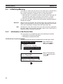
Initializing Memory . . . . . . . . . . . . . . . . . . . . . . . . . . . . . . . . . . . . . . . . . . . . . . . . . . . . . . . .
64
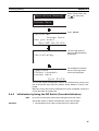
3-5
Transferring the System Program . . . . . . . . . . . . . . . . . . . . . . . . . . . . . . . . . . . . . . . . . . . . .
66
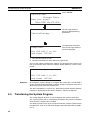
3-6
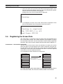
Registering the Screen Data. . . . . . . . . . . . . . . . . . . . . . . . . . . . . . . . . . . . . . . . . . . . . . . . . .
69
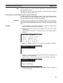
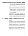
3-7
Setting the Conditions of Communications with the PLC by Using the Memory Switches.
71
3-8
Starting the Operation . . . . . . . . . . . . . . . . . . . . . . . . . . . . . . . . . . . . . . . . . . . . . . . . . . . . . .
77
3-9
Backlight OFF . . . . . . . . . . . . . . . . . . . . . . . . . . . . . . . . . . . . . . . . . . . . . . . . . . . . . . . . . . . .
78
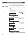
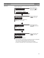
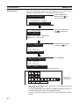
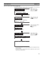
3-10 System Maintenance . . . . . . . . . . . . . . . . . . . . . . . . . . . . . . . . . . . . . . . . . . . . . . . . . . . . . . .
80
vii
TABLE OF CONTENTS
SECTION 4
NT11 Functions . . . . . . . . . . . . . . . . . . . . . . . . . . . . . . . . . . . .
85
4-1
Outline of Functions . . . . . . . . . . . . . . . . . . . . . . . . . . . . . . . . . . . . . . . . . . . . . . . . . . . . . . .
86
4-2
Screen Display . . . . . . . . . . . . . . . . . . . . . . . . . . . . . . . . . . . . . . . . . . . . . . . . . . . . . . . . . . . .
87
4-3
Areas for Control/Notification. . . . . . . . . . . . . . . . . . . . . . . . . . . . . . . . . . . . . . . . . . . . . . . .
89
4-4
Memory Tables . . . . . . . . . . . . . . . . . . . . . . . . . . . . . . . . . . . . . . . . . . . . . . . . . . . . . . . . . . .
94
4-5
Bar Graphs . . . . . . . . . . . . . . . . . . . . . . . . . . . . . . . . . . . . . . . . . . . . . . . . . . . . . . . . . . . . . . .
96
4-6
Numeral Setting . . . . . . . . . . . . . . . . . . . . . . . . . . . . . . . . . . . . . . . . . . . . . . . . . . . . . . . . . . .
97
4-7
Menu Screen Function. . . . . . . . . . . . . . . . . . . . . . . . . . . . . . . . . . . . . . . . . . . . . . . . . . . . . .
99
4-8
Password Screen Display Function . . . . . . . . . . . . . . . . . . . . . . . . . . . . . . . . . . . . . . . . . . . .
100
4-9
Display History Screen Function. . . . . . . . . . . . . . . . . . . . . . . . . . . . . . . . . . . . . . . . . . . . . .
101
4-10 Daily Report/Display History Printing Function. . . . . . . . . . . . . . . . . . . . . . . . . . . . . . . . . .
102
SECTION 5
Using Host Link/NT Link. . . . . . . . . . . . . . . . . . . . . . . . . . . . 107
5-1
Screen Creation Procedure . . . . . . . . . . . . . . . . . . . . . . . . . . . . . . . . . . . . . . . . . . . . . . . . . .
108
5-2
Outline of Host Link/NT Link Operation . . . . . . . . . . . . . . . . . . . . . . . . . . . . . . . . . . . . . . .
109
5-3
Memory Table Entries and Bar Graph. . . . . . . . . . . . . . . . . . . . . . . . . . . . . . . . . . . . . . . . . .
115
5-4
Numeral Setting . . . . . . . . . . . . . . . . . . . . . . . . . . . . . . . . . . . . . . . . . . . . . . . . . . . . . . . . . . .
126
5-5
NT11 Status Control . . . . . . . . . . . . . . . . . . . . . . . . . . . . . . . . . . . . . . . . . . . . . . . . . . . . . . .
129
5-6
Notification of the Operating Status to the PLC (Determining the NT11 Operating Status)
132
SECTION 6
Troubleshooting and Maintenance . . . . . . . . . . . . . . . . . . . . 135
6-1
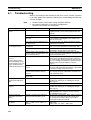
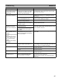
Troubleshooting . . . . . . . . . . . . . . . . . . . . . . . . . . . . . . . . . . . . . . . . . . . . . . . . . . . . . . . . . . .
136
6-2
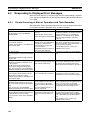
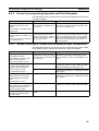
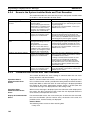
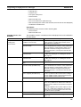
Responding to Displayed Error Messages. . . . . . . . . . . . . . . . . . . . . . . . . . . . . . . . . . . . . . .
138
6-3
Inspection and Cleaning . . . . . . . . . . . . . . . . . . . . . . . . . . . . . . . . . . . . . . . . . . . . . . . . . . . .
142
Appendices
A
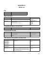
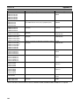
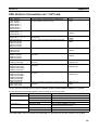
Specifications . . . . . . . . . . . . . . . . . . . . . . . . . . . . . . . . . . . . . . . . . . . . . . . . . . . . . . . . . . . .
145
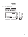
B
Dimensions . . . . . . . . . . . . . . . . . . . . . . . . . . . . . . . . . . . . . . . . . . . . . . . . . . . . . . . . . . . . . .
149
C
Transporting and Storing the NT11 . . . . . . . . . . . . . . . . . . . . . . . . . . . . . . . . . . . . . . . . . . .
151
D
Making the Cable . . . . . . . . . . . . . . . . . . . . . . . . . . . . . . . . . . . . . . . . . . . . . . . . . . . . . . . . .
153
E
Making the Cable for Connecting a Personal Computer . . . . . . . . . . . . . . . . . . . . . . . . . . .
155
F
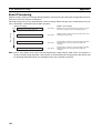
NT11 Internal Processing . . . . . . . . . . . . . . . . . . . . . . . . . . . . . . . . . . . . . . . . . . . . . . . . . . .
157
G
Model List . . . . . . . . . . . . . . . . . . . . . . . . . . . . . . . . . . . . . . . . . . . . . . . . . . . . . . . . . . . . . . .
159
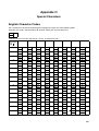
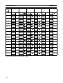
H
Special Characters . . . . . . . . . . . . . . . . . . . . . . . . . . . . . . . . . . . . . . . . . . . . . . . . . . . . . . . .
163
Index. . . . . . . . . . . . . . . . . . . . . . . . . . . . . . . . . . . . . . . . . . . . . 165
Revision History . . . . . . . . . . . . . . . . . . . . . . . . . . . . . . . . . . . 169
viii
About this Manual:
This manual describes the basic functions and operation procedures of the NT-series programmable
terminal NT11, its operations when connected to a PLC, and includes the sections described below.
Please read this manual carefully and be sure you understand the information provided before
attempting to install and operate the NT-series programmable terminal NT11.
Section 1 describes the operation functions, system configuration, and the direct connection function
of the NT11.
Section 2 describes the hardware settings, installation to an operation panel, connection to optional
devices and PLC.
Section 3 describes the operation of the System Menu and the maintenance of the NT11.
Section 4 describes the functions of the NT11 when it is connected to a PLC.
Section 5 describes how to use the NT11 when it is connected to the PLC using the host link or NT
link.
Section 6 describes the procedures to follow when the NT11 does not operate correctly.
APPENDIX describes the specifications and the method for making connecting cables, and includes
an area list for the PLC.
!WARNING Failure to read and understand the information provided in this manual may result in personal injury or death, damage to the product, or product failure. Please read each section
in its entirety and be sure you understand the information provided in the section and
related sections before attempting any of the procedures or operations given.
ix
Related Manuals and Their Contents:
The related manuals are listed below.
The @ symbol at the end of the manual number is the revision history symbol.
[Operating the programmable terminal and communicating with the host]
• NT11 Programmable Terminal User’s Manual (V084-E1-@)
- - - - - - - - - - - - - - - - - - - - - - - - - - - - - - - - - - - - - - - - - - - - - - - - - - - - - - - - - - - - - This manual
This user’s manual is the manual for the NT11-V@ itself.
The NT11 is a unit which integrates a programmable terminal body. This user’s manual describes the
functions and handling of the programmable terminal body.
[Creating and transferring screen data]
• NT-series Support Tool Operation Manual (V061-E1-@)
The screens displayed on the NT11 are created with the support tool and transferred to the NT11.
This manual describes how to create and transfer screen data.
x
PRECAUTIONS
This section provides general precautions for using the Programmable Terminal.
The information contained in this section is important for the safe and reliable application of the Programmable
Terminal. You must read this section and understand the information contained before attempting to set up or
operate a Programmable Terminal.
1
2
3
Intended Audience . . . . . . . . . . . . . . . . . . . . . . . . . . . . . . . . . . . . . . . . . . . . .
General Precautions . . . . . . . . . . . . . . . . . . . . . . . . . . . . . . . . . . . . . . . . . . . .
Safety Precautions. . . . . . . . . . . . . . . . . . . . . . . . . . . . . . . . . . . . . . . . . . . . . .
xii
xii
xii
xi
Intended Audience
1
1
Intended Audience
This manual is intended for the following personnel, who must also have
knowledge of electrical systems (an electrical engineer or the equivalent).
• Personnel in charge of introducing FA systems into production facilities.
• Personnel in charge of designing FA systems.
• Personnel in charge of installing and connecting FA systems.
• Personnel in charge of managing FA systems and facilities.
2
General Precautions
The user must operate the product according to the performance specifications described in the user’s manuals.
Before using the product under conditions that are not described in the manual or applying the product to nuclear control systems, railroad systems, aviation systems, vehicles, combustion systems, medical equipment, amusement
machines, safety equipment, and other systems, machines and equipment
that may have a serious influence on lives and property if used improperly,
consult your OMRON representative.
Make sure that the ratings and performance characteristics of the product are
sufficient for the systems, machines, and equipment, and be sure to provide
the systems, machines, and equipment with double safety mechanisms.
This manual provides information for using the Programmable Terminal. Be
sure to read this manual before attempting to use the software and keep this
manual close at hand for reference during operation.
!WARNING It is extremely important that Programmable Terminals and related devices be
used for the specified purpose and under the specified conditions, especially
in applications that can directly or indirectly affect human life. You must consult with your OMRON representative before applying Programmable Terminals to the above-mentioned applications.
!WARNING Do not use input functions such as PT touch switches for applications where
danger to human life or serious damage is possible, or for emergency switch
applications.
3
Safety Precautions
Read these safety precautions carefully and make sure you understand them
before using the Programmable Terminal so that you can use it safely and correctly.
Safety Conventions and
their Meanings
This user’s manual uses the following conventions and symbols to indicate
cautions, warnings, and dangers in order to ensure safe use of the NT11.
The cautions, warnings, and dangers shown here contain important information related to safety. The instructions in these cautions, warnings, and dangers must be observed.
The conventions used and their meanings are presented below.
!WARNING Indicates information that, if not heeded, could possibly result in loss of life or
serious injury.
xii
Safety Precautions
Caution
3
Indicates information that, if not heeded, could result in relatively serious or minor injury, damage to the product, or faulty operation.
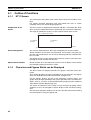
WARNING
Do not attempt to take the Unit apart and do not touch any
internal parts while the power is being supplied. Doing either of
these may result in electrical shock.
xiii
Safety Precautions
xiv
3
SECTION 1
Functions of the NT11
NT11 is a new programmable terminal (PT) which incorporates a host interface unit in a programmable terminal body. It
can be easily installed and used.
This section gives the operation examples and characteristics of the NT11 so that you will understand the applications of
the NT11.
1-1
Getting Starting . . . . . . . . . . . . . . . . . . . . . . . . . . . . . . . . . . . . . . . . . . . . . . . .
2
1-2
Role and Operation of NT11. . . . . . . . . . . . . . . . . . . . . . . . . . . . . . . . . . . . . .
2
1-2-1
Operations of NT11 . . . . . . . . . . . . . . . . . . . . . . . . . . . . . . . . . . . . .
3
Functions of NT11 . . . . . . . . . . . . . . . . . . . . . . . . . . . . . . . . . . . . . . . . . . . . .
4
1-3
1-4
1-5
1-6
1-3-1
Features. . . . . . . . . . . . . . . . . . . . . . . . . . . . . . . . . . . . . . . . . . . . . . .
4
1-3-2
Principal Functions of NT11. . . . . . . . . . . . . . . . . . . . . . . . . . . . . . .
5
1-3-3
Displays . . . . . . . . . . . . . . . . . . . . . . . . . . . . . . . . . . . . . . . . . . . . . .
6
1-3-4
System Keys . . . . . . . . . . . . . . . . . . . . . . . . . . . . . . . . . . . . . . . . . . .
7
System Configuration . . . . . . . . . . . . . . . . . . . . . . . . . . . . . . . . . . . . . . . . . . .
8
1-4-1
Peripheral Devices That Can Be Connected. . . . . . . . . . . . . . . . . . .
8
Direct Connection Function . . . . . . . . . . . . . . . . . . . . . . . . . . . . . . . . . . . . . .
9
1-5-1
NT Link . . . . . . . . . . . . . . . . . . . . . . . . . . . . . . . . . . . . . . . . . . . . . .
9
1-5-2
Functions of the Allocated Bits and Words . . . . . . . . . . . . . . . . . . .
10
Before Operating. . . . . . . . . . . . . . . . . . . . . . . . . . . . . . . . . . . . . . . . . . . . . . .
12
1
Getting Starting
1-1
Section 1-1
Getting Starting
To ensure that the NT11 works correctly, carefully observe the following when
installing and handling it.
Location
Do not install the NT11 in a location subject to the following conditions;
• Near a computer, radio transmitter or receiver, etc.
• Dust, chemicals, or steam
• Severe temperature fluctuations
• High humidity and condensation
• Strong electrical or magnetic fields
• Poor ventilation
• Severe vibration
Handling
Do not;
• Subject the NT11 to strong shocks or vibrations
• Put heavy objects on the NT11
• Supply a voltage different from the specified voltage
• Disassemble or modify the NT11
Cautions on Cleaning
To clean the front panel, use a soft, dry cloth. If it is very dirty, use diluted (2%)
neutral detergent.
Do not use volatile solvents such as benzene, thinner, or a chemically treated
cloth. Their use will cause deformation or discoloration.
Cautions on Afterimage
If the same screen contents are kept displayed for a long time, an afterimage
may occur. To prevent this problem, either set the afterimage prevention function or make a program which periodically changes the displayed screen.
Cautions on Operating the System Keys
Do not operate the system keys with sharply pointed objects, such as your fingernails or a screwdriver.
This could break the film.
1-2
Role and Operation of NT11
NT11 is a programmable terminal used to display and transmit the information
in an FA site. The following gives a general description of the role and operation of the NT11 for those who use a programmable terminal (PT) for the first
time.
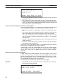
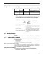
Production Line Status Monitoring
The NT11 displays real-time information about the system and equipment
operating status, etc.
Line 1 Status
Machine:NT11-SF121
Product: 137 units
75%
2
Role and Operation of NT11
Messages
Section 1-2
The NT11 warns of system or equipment failures and prompts the appropriate
remedial action.
A l a r m
Assembly line B
Positioning pin
Panel Switch Functions
The NT11 can be used in place of external data input equipment such as an
operation panel, to transmit data to a PLC.
Positioning
X-AXIS
100 point
Y-AXIS
150 point
Z-AXIS
80 point
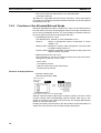
1-2-1
Operations of NT11
Displays Screens
The information to be displayed (screen data) can be created on a computer
by using support tools and stored in the NT11. The screen data can be displayed on the NT11 in response to the instructions from a PLC or system keys
operation.
PLC
The screen data designated by
instructions from PLC or System
keys operation is displayed.
Receives Data from a PLC
NT11 can be connected to a PLC by a host link or NT link and receive necessary data from the PLC.
Host link, NT link
PLC
OMRON's PLC
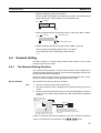
Sends Data to a PLC
Data input through a numeric key can be sent to a PLC.
Numeric keys
PLC
ON/OFF information,
numeric data, etc.
3
Functions of NT11
Screen Data
Section 1-3
The screen data to be displayed on the NT11 can be created by a computer
by using support tools. Connect the NT11 to an IBM PC/AT or compatible with
an RS-232C cable so that the screen data are transferred to the NT11.
Create screen data.
RS-232C
PC/AT
(support tools)
Screen data
This connection is made only to
transmit the screen data by using
NT11 and tools.
1-3
Functions of NT11
The NT11 has the following features and functions;
1-3-1
Features
Downsized Body
• The NT11 has the thinnest depth (31 mm or less in the panel) in the NT
series.
• It is very compact, with a width of 218 mm and a height of 113 mm.
• Features three ports: for RS-232C, RS-422A, and printer output.
• The tool connectors and the PLC communication connectors are used in
common.
Construction Best Suited to the FA Environment
• Easy-to-read screen even in direct sunlight.
• Waterproofed to a standard equivalent to IP65 and NEMA4.
160 dots
64 dots
Wide angle of visibility ±20°
A Host I/F Unit, Screen Data Memory, and a system program transfer ROM are All Incorporated
• There is no complicated installation work except a simple connection to a
PLC.
• A flash memory is used for the screen data memory. There is no need of
backup battery.
• A host link (direct), and an NT link are standard equipment.
4
Functions of NT11
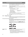
1-3-2
Section 1-3
Principal Functions of NT11
Functions Related to the Data Display
• Character display
Characters of standard and double-width can be displayed. Characters can flash or be
highlighted.
• Memory data display
Contents of the character-string memory table and the numeral memory table can be
displayed. The memory table contents can be changed from the PLC.
• Bar graph display
Bar graphs corresponding to the contents of the numeral table can be displayed.
Functions Related to the Data Input
• Input by the system key
Data can be input, and the displayed screen
changed, by using the numeric keys, function keys,
and arrow keys on the panel of the NT11.
• Numeric setting function
The numeric values can be input at the operation
site by the system key and sent to the PLC.
Other Functions
• Communications with a PLC
The host link, NT link is used to connect to a PLC for data communication.
• System function
The system setting and maintenance can be executed by using the
System Menu on the screen.
• Screen data creation
The screen data can be created by using support tools on the computer
and stored in the unit.
5
Functions of NT11
1-3-3
Section 1-3
Displays
The NT11 can display elements such as characters, numeric value, and bar
graphs on a screen. The screen data displayed on the NT11 are created by
using support tools on a computer.
Characters
(character string)
Characters (text)
Bar graph
Characters (text)
Line 1 Status
Machine:NT11-SF121
Product:137 units
75%
Numeric value
(Numeral table)
Characters and marks which do not need to be changed can be written
directly to the screen.
Characters (character-string memory table)
Character-strings stored in the character-string memory table are displayed.
The display characters can be changed by changing the data stored in the
character-string memory table.
Numeric Values (numeral memory table)
Numbers stored in the numeral memory table are displayed. The display numbers can be changed by changing the data stored in the numeral table. Hexadecimal values can also be displayed.
Bar Graphs
The bar graph extends and contracts in proportion to the data stored in the
numeral memory table. A percentage value can also be displayed simultaneously.
Marks
Marks can be designed, created, and handled like characters by the user.
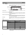
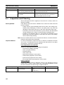
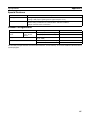
Comparison with the NT11S
Model
Dimensions
NT11
218 x 113 x 38.2 mm (W x H x D)
Resolution
Effective display area
160 x 64 dots (4.24 inches)
100 x 40 mm
Display color
Panel cut-out size (W x H)
Black & white (with yellow mode)
204.2 x 98.8 mm
Max. number of registered screens
Screen data capacity
250
32 KB
Function keys
Other Keys
4
Numeric Keys, Cursor Keys, Function Keys
Special functions
Emergency transfer mode*
Backlight service life
DIP switch pin 3
50,000 hours min.
Communications
Host Link Speed
Up to 115,200
Compatibility (Screen data types that can NT11-V1, NT11S
be used.)
Basic performance
NT11S
None
10,000 hours min.
9,600/19,200
NT11S
* Emergency transfer mode: When power to the NT11 is turned ON with DIP
switch pin 3 turned ON, data transfer mode will be entered directly without
any other operation.
6
Functions of NT11
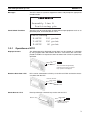
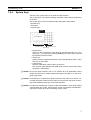
1-3-4
Section 1-3
System Keys
The NT11 has system keys on its panel for input functions.
The system keys are used for inputting numerical values and for notifications
to the PLC.
The system keys can be classified into the three types shown below.
- Numeric keys
- Arrow keys
- Function keys
NT11
Screen display
Function keys
Numeric keys
Arrow keys
• Numeric keys
These are the numeral keys from [0] to [9], the decimal point key [.], the
sign key [+/–], the [CLR] key and the [ENTER] key. These keys are used
for inputting numerical values.
• Arrow keys
Used to select the required numerical value input field when there is more
than one on the screen.
• Function keys
Used for notifications from the NT11 to the PLC.
Also used to switch between the RUN mode and the system menu when
the power is switched on.
!Caution Do not use input functions such as PT function keys for applications where
danger to human life or serious property damage is possible, or as the emergency stop switch.
!Caution If function keys are pressed in rapid succession, their inputs may not be successfully received. Confirm that the input of a function key has been successfully received before moving on to the next operation.
!Caution Do not press function keys carelessly while the backlight is off or while nothing
is displayed on the screen. Otherwise the system may operate unpredictably.
Only press function keys after confirming system safety.
7
System Configuration
1-4
Section 1-4
System Configuration
This section shows the configuration of a system that uses an NT11. For
details on product models, refer to Appendix G Model List (page 159).
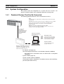
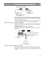
1-4-1
Peripheral Devices That Can Be Connected
The following peripheral devices can be connected to an NT11.
Host
Controls the NT11 as required while controlling machines and monitoring the
production line.
Host Link: CS-series/CJ-series/C-series PLCs, CVM1/CV-series PLCs, SRM1
Can be connected to CPU Units, Host Link Units, and SRM1. However,
connection is not possible to some models of CPU Unit and SRM1
(pages 23 and 39).
NT Link: C-series PLCs, CVM1/CV-series PLCs, SRM1
Can be connected to CPU Units and SRM1. However, connection is not
possible to some models (pages 51 and 55).
RS-232C cable
(15 m max.)
An RS-422A/485 cable
(500 m max.) can be
connected through an
RS-232C/RS-422A
Adapter.
Personal computer
Running Windows 95, 98,
NT, 2000, Me, XP
NT Support Tool
Used to create screens for the
NT11 at the personal computer
and transfer them to the NT11,
and to make NT11 settings.
System installer
Used to change the system
program of the NT11.
NT11
Displays production line monitoring and
commands to the operation site, and
notifies the switch ON/OFF status and
numeric value inputs to the host.
• NT Support Tool (page 22)
NT-series Support Tool Version 4.7 for Windows (Made by OMRON)
• NT-ZJCAT1-EV4.7 (CD-ROM version for IBM PC/AT or compatible
computers)
• System installer (page 22)
System Installer (made by OMRON)
The System Installer is supplied as a standard accessory with the NT Support Tool (NT-ZJCAT1-EV4.7).
8
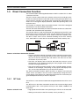
Direct Connection Function
1-5
Section 1-5
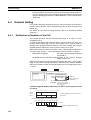
Direct Connection Function
The communication method applied between the NT11 and the PLC is either
a host link or NT link.
The NT11 can be used to refer to the contents necessary for the display information or to allocate the bits and words used for storing the input data to any
area in the PLC. The NT11 can directly write and read such allocated bits and
words so as to change the display elements, control the operating status, and
notify the status.
This function is called the “direct connection function”. The NT11 is designed
exclusively for use with the direct connection.
The bits and words allocated by the direct connection function are called “allocated bit” and “allocated word” respectively.
This function allows to read the information to be displayed on the NT11 from
the memory area in the PLC and to write it to the memory table in the NT11.
Also, the data input on the NT11 can be written to the PLC’s memory area.
The NT11 screen status can be switched according to the PLC’s memory
area, and the NT11’s status data can be written to the PLC’s memory area.
NT11
PLC
Data memory area
Internal relay area
Auxiliary relay area
Timer/counter
Features of the Direct Connection Function
• The bits and words referring to operating status and work instruction information and those for storing input data can be freely allocated to almost
any part of the PLC memory. Bits and words in the PLC can be referenced from any memory table.
• The NT11 can directly refer to PLC bit and word data so that it can be
connected to a PLC without changing the PLC program which controls
currently running production line.
• The area to control and notify the NT11 status, including display screens,
ON/OFF of the backlight, and printing of daily reports and display histories, can be freely allocated to any part of the PLC memory.
The direct connection function allows the NT11 to directly read and write
almost all bits and words in the PLC and to automatically change the NT11
screen display. This function can reduce the load on the PLC so that the program development efficiency of the PLC improves.
1-5-1
NT Link
The NT link is a new communication method applied between the NT11 and a
PLC.
The NT link uses the direct connection function and can execute high speed
communications with a CPU (built-in NT link) of the CQM1, C200HS, and
other PLCs.
Features of the NT Link
• High speed communications with specific types of PLCs can be executed.
• Writing in units of bits to the PLC memory area is possible. (*)
9
Direct Connection Function
Section 1-5
• This can be used even when the PLC is in the RUN mode.
(*) Except a DM area.
The NT link is compatible with the host link. The NT11 screen data and the
PLC programs handled by the host link direct connection can be used with for
the NT link as they are.
1-5-2
Functions of the Allocated Bits and Words
Elements displayed on the NT11 and the NT11 status can be allocated to the
bits and words of the PLC. By changing the contents of the bits and words, the
NT11 can be controlled by the PLC. It is also possible to send data to the PLC
by pressing the function keys on the panel of the NT11.
• Controlling the NT11 by a PLC
The following NT11 functions can be controlled by a PLC.
Screens:
Display of designated screens, confirmation of screen
numbers, etc.
Memory tables: Writing to a memory table, copying from a memory table
to another memory table, etc.
System control: ON/OFF of backlight, control of output of daily reports and
display histories at a printer.
• Notifying from the NT11 to a PLC
Data in the NT11 is sent to a PLC when a numeric key is pressed. The following types of data are sent to a PLC.
- NT11 status
- Password input status
- Numeric values input by the numeral keys
- Function key input status
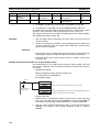
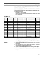
Functions of Display Elements
• Numeral memory table
Allocation destination: Word
Numeral memory
table entry 1
NT11
(TIM003)
PLC
CIO/IR 0005
Numeral memory table entry 150 (CIO/IR 0005)
Allocate numeral memory table entries to arbitrary words in the PLC. If word
contents change when corresponding numeral memory table entry is displayed on the screen, the value on the screen will also change. Monitoring of
words can also be made easily.
Reading and writing are executed so that the contents of allocated words are
always the same as those of the numeral memory table entries.
10
Direct Connection Function
Section 1-5
• Character-string memory table
Allocation destination: Word
NT11
PLC
("a", "b")
("c", "d")
("e", "f")
Character-string memory table entry 1
Number of allocated words: 3
First word: DM0100
Allocate character-string memory table entries to arbitrary words in the PLC. If
word contents change when corresponding character-string memory table
entry is displayed on the screen, the value on the screen will also change.
Messages can be displayed easily.
Reading and writing are executed so that the contents of allocated words are
always the same as those of the character-string memory table entries.
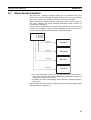
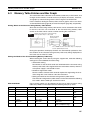
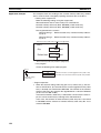
Functions of the PT Status Control Area (PLC to NT11)
The “PT status control area” is used to control the NT11 status. When data is
written to this area in the PLC, the NT11 reads the contents and operates
according to the contents.
[Example of the PT status control area application]
When data is written to the PT status control area, the NT11 will operate as
given below.
Screen 3
display
NT11
PLC
PT status control area
0003
Screen switch setting
0050
Memory table entry
1007
Copy setting
8010
PT status control bits
Numeral memory table entry 50
Copy
Numeral memory table entry 7
Printing of daily reports or display histories
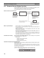
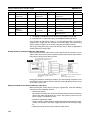
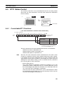
Functions of the PT Status Notify Area (NT11 to PLC)
The “PT status notify area” is used to notify the changes of the NT11 status.
When a change is made in the NT11 status, the change is written to this area
in the PLC. By reading the data from the area, the NT11 status can be
checked.
11
Before Operating
Section 1-6
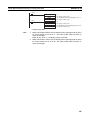
[Example of the PT status notify area application]
When a change is made in the NT11 status, such change will be notified to
the PT status notify area as mentioned below.
NT11
12345678
PLC
Numeral memory table entry 13
12345678
PT status notify area
Currently display screen
Content update memory table entry
PT status
Allocated word (numeral table 13)
12345678
Start
Start + 1
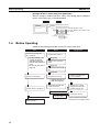
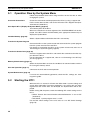
1-6
Before Operating
Follow the procedure given below to start the system of the NT11.
PLC
Check and change the
PLC settings.
· For the host link, refer
to page 22 and the
manuals for the host
link unit and peripheral
tools.
· For the NT link, refer to
page 50.
NT11
Support tool
Set the DIP switches.
(page 18)
Install to the operation
panel.
(page 19)
Connect the power supply.
(page 20)
Connect to the NT11.
Connect to the PLC.
Install the support tool
in the computer.
· (Host link: page 22)
· (NT link: page 50)
Check the settings and
communications.
Create the PLC program.
Transfer the
screen data.
(page 69)
Start operation.
12
Transfer the system
program by using the
system transfer tool.
Create the screens.
(refer to Section 4 and the
manuals for the support tools)
Before Operating
Section 1-6
Reference
Use support tool NT-series Support Tool (NT-ZJCAT1-EV4.7).
!Caution Carefully check the operation of all screen data and host programs before
using them.
Otherwise the system may operate unpredictably.
Refer to the following manuals for the equipment and software.
Device or Software
NT11
User’s Manual
System Installer
NT Support Tool
PLC
Manual Title
NT-series Support Tool for Windows (Ver. 4.7) Operation Manual
NT-series Support Tool for Windows (Ver. 4.7) Operation Manual
Cat. No.
V084-E1-@
V061-E1-@
V061-E1-@
SYSMAC CPM1 Operation Manual
W262-E1-@
SYSMAC CPM1A Operation Manual
SYSMAC CPM2A Operation Manual
W317-E1-@
W352-E1-@
SYSMAC CPM2C Operation Manual
SYSMAC C200H Operation Manual (for CPU01/03/11) (Programming)
W356-E1-@
W130-E1-@
SYSMAC C200H Operation Manual (for CPU21/23/31) (Programming)
SYSMAC C200HS Installation Guide
W217-E1-@
W236-E1-@
SYSMAC C200HS Operation Manual (Programming)
SYSMAC C200HX/HG/HE (-Z) Installation Guide
W235-E1-@
W302-E1-@
SYSMAC C200HX/HG/HE Operation Manual
SYSMAC C200HX/HG/HE-Z Operation Manual
W303-E1-@
W322-E1-@
SYSMAC CQM1/CPM1/CPM1A/SRM1 Programming Manual
SYSMAC CQM1H Operation Manual
W228-E1-@
W363-E1-@
SYSMAC CVM1/CV500/CV1000/CV2000/CVM1 Operation Manual: Ladder Diagrams
CS Series Programmable Controllers Operation Manual
W202-E1-@
CJ Series CJ1G-CPU@@-E Programmable Controllers Operation Manual
CS/CJ Series Programming Manual
W393-E1-@
W394-E1-@
CS/CJ Series Serial Communications Boards/Units Operation Manual
SYSMAC CQM1H Series Serial Communications Board Operation Manual
W336-E1-@
W365-E1-@
CompoBus Master
Control Unit
SRM1 (-V2) Operation Manual
W318-E1-@
Programming Tools
SYSMAC Support Software Operation Manual: C-series PLCs
SYSMAC Support Software Operation Manual: CVM1 PLCs
W248-E1-@
W249-E1-@
SYSMAC CPT User Manual and Quick Start Guide
W332-E1-@
W333-E1-@
CX-Programmer Ver. 4 User Manual
SYSMAC C Series Host Link Unit System Manual
W425-E1-@
W143-E1-@
SYSMAC CVM1/CV Series Host Link Operation Manual
SYSMAC C200HW-COM01 C200HW-COM02-V1 to C200HW-COM06-EV1 Communications Board Operation Manual
W205-E1-@
W304-E1-@
Host Link Unit/
Serial Communications Board
W339-E1-@
13
Before Operating
14
Section 1-6
SECTION 2
Hardware Settings and Connections
This section describes the settings of the NT11, connections to a PLC, and other hardware settings.
2-1
Description of Parts and Settings . . . . . . . . . . . . . . . . . . . . . . . . . . . . . . . . . .
16
2-1-1
Description of Parts . . . . . . . . . . . . . . . . . . . . . . . . . . . . . . . . . . . . .
16
2-1-2
DIP Switch Settings . . . . . . . . . . . . . . . . . . . . . . . . . . . . . . . . . . . . .
18
Installation. . . . . . . . . . . . . . . . . . . . . . . . . . . . . . . . . . . . . . . . . . . . . . . . . . . .
19
2-2-1
Installation to the Operation Panel . . . . . . . . . . . . . . . . . . . . . . . . . .
19
2-2-2
Power Supply Connection . . . . . . . . . . . . . . . . . . . . . . . . . . . . . . . .
20
2-2-3
Wiring the Ground Wire . . . . . . . . . . . . . . . . . . . . . . . . . . . . . . . . . .
21
2-3
Connecting to the NT Support Tool . . . . . . . . . . . . . . . . . . . . . . . . . . . . . . . .
22
2-4
Connection to a PLC by the Host Link (RS-232C Type) . . . . . . . . . . . . . . . .
22
2-4-1
Compatible PLCs . . . . . . . . . . . . . . . . . . . . . . . . . . . . . . . . . . . . . . .
23
2-4-2
Connecting the NT11 . . . . . . . . . . . . . . . . . . . . . . . . . . . . . . . . . . . .
24
2-4-3
PLC Switch Settings . . . . . . . . . . . . . . . . . . . . . . . . . . . . . . . . . . . . .
27
Connection to a PLC by the Host Link (RS-422A Type) . . . . . . . . . . . . . . . .
38
2-2
2-5
2-6
2-5-1
Compatible PLCs . . . . . . . . . . . . . . . . . . . . . . . . . . . . . . . . . . . . . . .
38
2-5-2
Parts Required for Connection . . . . . . . . . . . . . . . . . . . . . . . . . . . . .
40
2-5-3
Method for Connection. . . . . . . . . . . . . . . . . . . . . . . . . . . . . . . . . . .
40
2-5-4
Connector Specifications and Wiring for Each Unit . . . . . . . . . . . .
41
2-5-5
PLC Switch Settings . . . . . . . . . . . . . . . . . . . . . . . . . . . . . . . . . . . . .
42
Connection to a PLC by the NT Link (RS-232C Type) . . . . . . . . . . . . . . . . .
50
2-6-1
Compatible PLCs . . . . . . . . . . . . . . . . . . . . . . . . . . . . . . . . . . . . . . .
50
2-6-2
Connecting the NT11 . . . . . . . . . . . . . . . . . . . . . . . . . . . . . . . . . . . .
54
2-7
Connection to a PLC by the NT Link (RS-422A Type) . . . . . . . . . . . . . . . . .
55
2-8
Connecting a Printer . . . . . . . . . . . . . . . . . . . . . . . . . . . . . . . . . . . . . . . . . . . .
57
2-8-1
57
How to Connect . . . . . . . . . . . . . . . . . . . . . . . . . . . . . . . . . . . . . . . .
15
Description of Parts and Settings
2-1
Section 2-1
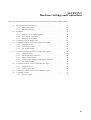
Description of Parts and Settings
Before getting to the operation, confirm the names and functions of parts.
Also set the DIP switches on the NT11.
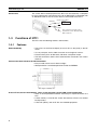
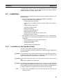
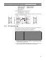
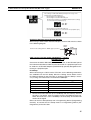
2-1-1
Description of Parts
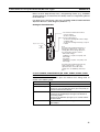
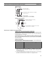
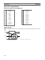
Front View
POWER LED
Lit when the
power is supplied.
Arrow keys
Used to select the
required numerical
value input field when
there is more than one
on the screen.
RUN LED
Lit when the
communication
status is normal.
Numeric keys
Used for inputting
numerical values on
screens that require
numerical value input.
Function keys
Used for direct
notifications to the PLC.
Reference
Display
An LCD screen with a backlight.
The NT11 comes in two body colors.
• NT11-SF121-EV1:Beige
• NT11-SF121B-EV1:Black
16
Description of Parts and Settings
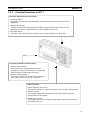
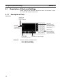
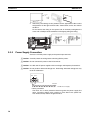
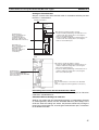
Section 2-1
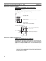
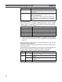
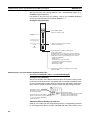
Rear View
Connector for parallel interface connection
Connect the printer cable here.
(Interface conforms to Centronics specifications)
Contrast control
Use a fine phillips screwdriver.
Turn clockwise to increase the brightness.
DIP switch
Set various system statuses
with these switches.
RS-422A terminal block
Connect the PLC cable here.
Power input terminals
Connect the power to the
NT11 at these terminals.
RS-232C connector
Connect the cable that connects
the PLC or support tool here.
17
Description of Parts and Settings
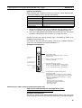
2-1-2
Section 2-1
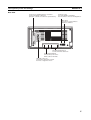
DIP Switch Settings
Set the NT11 operation status with the DIP switches located in the bottom
right corner on the rear side of the body.
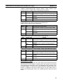
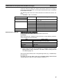
DIP Switch Settings
Factory setting: ALL OFF
DIP Switch Pin
Function
SW1
1
0
RS-422A terminating resistance used
Not used
SW2
1
0
Screen data forced initialize effective
Ineffective
SW3
1
0
Emergency transfer mode
Ineffective
SW4
1
0
Switching to the System Menu disabled
Enabled
SW5
SW6
Reserved.
1 System program erase enabled
0
Disabled
Emergency transfer mode: When power to the NT11 is turned ON with DIP
switch pin 3 turned ON, data transfer mode will be
entered directly without any other operation.
!Caution In addition to the DIP switches, set also the “Comm. Method”, “Host Link
Speed”, “Automatic Reset”, etc. at the memory switches. For these settings,
refer to 3-7 Setting the Conditions of Communications with the PLC by Using
the Memory Switches (page 71).
!Caution After changing the switch settings, always press the reset switch or turn the
power off and back on.
Otherwise the system will not operate as expected.
!Caution Confirm system safety before turning the power ON/OFF or resetting.
Otherwise the system may operate unpredictably.
Correct Use
Use the “System program erase” function only when changing the system
program.
It the system program is erased, it will not be possible to use the functions of
the NT11 unless another system program is transferred.
18
Installation
Section 2-2
If the DIP switch settings have been changed when the NT11 is powered,
reset the power to the NT11. The changes with the DIP switches become
effective only after the power supply is reset.
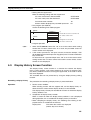
2-2
Installation
Install the NT11 to the operation panel and connect the power to the NT11 as
described below.
1. Do not install the unit at sites subject to the following conditions.
Otherwise, the product may malfunction.
• Severe temperature variations
• Temperature or humidity outside the ranges stated in the specifications
• High humidity, condensation
• Splashing chemical agents
• Severe oil splashing
• Corrosive or flammable gases
• Strong vibrations or shocks
• Direct exposure to wind and rain (outdoor sites)
• Strong ultra-violet irradiation
2. Take adequate measures to ensure shielding if the unit is used at a location subject to any of the following conditions. Otherwise, the product may
malfunction.
• Static electricity, or noise from other equipment
• Strong electromagnetic fields
• Nearby power cables
• Potential exposure to radioactivity
2-2-1
Installation to the Operation Panel
The NT11 can be flush mounted to an operation panel.
Use the panel fittings and tools included in the product package and follow the
procedure below.
!Caution On unpacking the unit, check its external appearance and confirm that there is
no damage. Also confirm that there is no abnormal noise on shaking the unit
lightly. The product may malfunction if it is damaged.
!Caution During work at the panel, take care to ensure that no metal scraps enter the
unit.
Otherwise, the product may malfunction.
!Caution The thickness of applicable operation panel is 1.6 mm to 4.8 mm. All fittings
must be tightened uniformly to a torque of 0.5 to 0.6 N·m in order to ensure
water- and dust-resistance. The panel must not be soiled or warped, and must
be able to support an installation that will remain secure and strong.
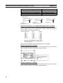
1,2,3...
1. Open a hole, shown below, in the panel and install the NT11 from the front
side of the panel.
19
Installation
Section 2-2
mm
98.8 +0.5
0 mm
+0.5 mm
204.2 0 mm
2. Attach the panel fittings at four positions for the upper/lower sides and at
two positions for the right and left sides, shown below, on the rear side of
the NT11.
Fit the hook of the fitting in the square hole in the body and tighten the
screw with a Phillips head screwdriver while lightly pulling the fitting.
2-2-2
Power Supply Connection
Connect a 24 VDC power supply to the power input terminals.
!Caution Carefully check the wiring before switching ON the power.
!Caution Do not connect AC power to the DC terminals.
!Caution Use DC and AC power supplies with low voltage and frequency fluctuations.
!Caution Do not perform withstand voltage test. Performing withstand voltage test may
result in malfunction.
0 V 24 V
+
Breaker
24 VDC Power Supply
• Noise prevention
The NT11 has a noise preventive feature against the power supply line
noise. To further reduce noise, connect a noise filter to the power line.
This will drastically reduce the ground noise.
20
Installation
Section 2-2
• Power supply
Applicable power supply specifications are as follows.
Item
Value
Power supply voltage
Allowable power supply voltage
fluctuation range
Power supply capacity
24 VDC
20.4 VDC to 26.4 VDC
(24 VDC –15%, +15%)
10 W or lower
• Parts used for connection
Use crimp terminals to connect the power supply to the power input terminals. Recommended crimp terminals for M3.5 are given below.
!Caution For the connection to the power supply terminal block, twisted wires of 2 mm2
or greater cross sectional area and M 3.5 size crimp terminals must be used.
Tighten the screws on the terminal block to a torque of 0.5 N×m.
Otherwise fire may occur.
Fork type
Round type
7 mm or less
7 mm or less
[Recommended terminals]
Maker
Note
Type
(fork type)
Type
(round type)
Japan Solderless Terminal MFG
Fuji Terminal
2-YS3A
2-YAS3.5
2-3.5
V2-S3.5
Nichifu Terminal
2Y-3.5
2-3.5
Applicable Wire
(stranded wire)
1.04 to 2.63 mm2
When surge noise occurs in the DC power supply, connect a Transistor Voltage Suppressor (TVS) between the 24-V and 0-VDC terminals.
Recommended TVS model: 1.5KE33CA
Manufacturers: Vishay Intertechnology Inc, STMicroelectronics
24 VDC
TVS
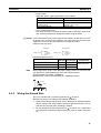
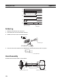
2-2-3
Wiring the Ground Wire
The PT is provided with a functional ground (FG:
) terminal.
Wire the FG terminal according to the following conditions.
1. Ground according to Figure when there is difference in potential between
the PT and host. Do not ground the functional ground of the PT if it is far
from the host and one-point grounding is difficult.
2. Do not ground the functional ground (FG: ) of the PT if it is mounted to
the same panel as devices that generate noise, such as motors and inverters.
21
Connecting to the NT Support Tool
Section 2-3
PT
Host
One-point
grounding
Note
2-3
Ground correctly to prevent malfunctions caused by noise.
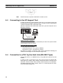
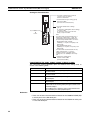
Connecting to the NT Support Tool
In order to install the system program in the NT11, or to transmit screen data
created with the NT Support Tool to the NT11, the NT11 must be connected to
a personal computer with an RS-232C cable.
The NT11 connects with the RS-232C cable from a personal computer at the
RS-232C serial port.
Serial port A
(RS-232C, 9-pin)
Communication Conditions
The communication conditions are automatically set when the system installer
and NT Support Tool are started.
Recommended Connector Cable
Use the cable indicated below.
• XW2Z-S002 (length: 2 m), made by OMRON
(D-SUB 9-pin, male Û D-SUB 9-pin, female)
For details on making a connector cable, refer to Appendix E Making the
Cable for Connecting a Personal Computer (page 155).
2-4
Connection to a PLC by the Host Link (RS-232C Type)
Connect the NT11 to an OMRON PLC by using RS-232C type the host link
method.
In order to make a connection to the PLC using the host link method (RS232C type), the “Comm. Type” memory switch of the NT11 must be set to
“host link”, and the “Comm. Port” memory switch must be set to “RS-232C”.
For details on memory switch settings, refer to 3-7-1 Selecting the Host Communication Method (page 73).
22
Connection to a PLC by the Host Link (RS-232C Type)
2-4-1
Section 2-4
Compatible PLCs
Some models and series of OMRON PLCs have the host link function built in.
Check the model and series of the PLC against the type of host link unit
before making the connections.
The compatible PLCs are listed in the table below.
PLC
Series
Units with Built-in Host Link
Function
CPU Units Connectable with
Host Link Units or Expansion
Communication Board
CS Series
CS1G-CPU42/43/44/45-EV1
CS1H-CPU63/64/65/66/67-EV1
CS1G-CPU42H/43H/44H/45H
CS1H-CPU63H/64H/65H/66H/
67H
CS1G-CPU42/43/44/45-EV1
CS1H-CPU63/64/65/66/67-EV1
CS1G-CPU42H/43H/44H/45H
CS1H-CPU63H/64H/65H/66H/
67H
CS1W-SCU21
CS1W-SCB21
CS1W-SCB41
CS1G
CS1H
CS1G-H
CS1H-H
CJ Series
C Series
CJ1G-CPU44/45
---
CJ1W-SCU41
C200H-LK201-EV1
CJ1G
C200HS
C200HE
C200HE-Z
C200HG
C200HG-Z
C200HX
C200HX-Z
C200HS-CPU21/23/31/33-E
CJ1G-CPU44/45
C200HS-CPU01/03/21/23/31/
33-E
C200HE-CPU11/32/42-E
C200HE-CPU11/32/42-ZE
C200HG-CPU33/43/53/63-E
C200HG-CPU33/43/53/63-ZE
C200HX-CPU34/44/54/64-E
C200HX-CPU34/44/54/64/65/
85-ZE
---
---
C200HS
C200HE-CPU42-E
C20HE-CPU42-ZE
C200HE-CPU32/42-E
C200HE-CPU32/42-ZE
C200HW-COM02/04/ C200HE
05/06-EV1
C200HE-Z
C200HG-CPU43/63-E
C200HG-CPU43/63-ZE
C200HG-CPU33/43/53/63-E
C200HG-CPU33/43/53/63-ZE
C200HG
C200HG-Z
C200HX-CPU44/64-E
C200HX-CPU44/64/65/85-ZE
C200HX-CPU34/44/54/64-E
C200HX-CPU34/44/54/64/65/
85-ZE
C200HX
C200HX-Z
CPM1-10/20/30CDR-@
+CPM1-CIF01
---
---
CPM1A-10/20/30/40CD@-@
+CPM1-CIF01
CPM2A-30/40/60CD@@-@
+CPM1-CIF01
(Peripheral port connection)
---
---
---
---
CPM2A
CPM2C-10/20@@@@@@-@
(*1)
CQM1-CPU21-E
CQM1-CPU41/42/43/44-EV1
CQM1H-CPU11/21/51/61 (*2)
---
---
CPM2C
---
---
CQM1
Host Link Unit/
Communication
Board
Connectable
to
CPM1
CQM1H-CPU51/61
CQM1H-SCB41
CQM1H
CVM1
CVM1-CPU01-EV2
Series (*3) CVM1-CPU11-EV2
CVM1-CPU21-EV2
CVM1-CPU01-EV2
CVM1-CPU11-EV2
CVM1-CPU21-EV2
CV500-LK201
CVM1
CompoBus/S
Master
Unit
---
---
SRM1
SRM1-C02-V1
*1: Use a CPM2C-CN111 or CS1W-CN114/118 Connecting Cable, CPM1-CIF01 RS-232C Adapter, or CPM1CIF11 RS-422A Adapter to connect.
23
Connection to a PLC by the Host Link (RS-232C Type)
Section 2-4
*2: The CQM1H-CPU11 does not have a built-in RS-232C port, so connect to the PT at the peripheral port
with a CS1W-CN118 Connecting Cable.
*3: CPU Units of CVM1/CV-series PLCs without the suffix -EV@ cannot be connected.
2-4-2
Connecting the NT11
Refer to the illustrations below to select the appropriate cable for the unit connectors and connect the NT11 to the PLC.
To make a connector cable, refer to Appendix D Making the Cable (page 153).
!Caution Before inserting or removing the connectors, make sure that the NT11 and the
PLC are turned OFF.
!Caution After connecting a communication cable, always secure it with the screws.
Otherwise the cable may disconnect, causing operation to fail.
!Caution The cable’s tensile load is 30 N. Do not subject it to loads greater than this.
Otherwise a discontinuity may occur, causing operation to fail.
Connecting to a PLC with a 25-pin Connector
Use a connector cable with a 25-pin connector on one end and a 9-pin connector on the other end (NT11 side) to connect the NT11 to a PLC with a 25pin connector.
NT11
Host link unit/CPU unit
C200H,
C200HS
Host I/F connector
(RS-232C 9-pin type)
9-pin connector
25-pin connector
RS-232C connector cable
Connecting to a PLC with a 9-pin Connector
Use a connector cable with a 9-pin connector on both ends to connect the
NT11 to a PLC with a 9-pin connector.
Host link unit/CPU unit
NT11
C200H,
C200HS
Host I/F connector
(RS-232C 9-pin type)
9-pin connector
9-pin connector
RS-232C connector cable
The method for connection between the RS-232C ports of the NT11 and the
host is described here.
Recommended Connector Cable
When making the connector cable, as far as possible use the recommended
connectors, connector hoods, and cables indicated in the table below. Some
Units come supplied with one connector and one connector hood.
24
Connection to a PLC by the Host Link (RS-232C Type)
Section 2-4
Check the required components and prepare them in advance.
Name
Model
Remarks
XM2A-0901
9-pin
Made by OMRON
XM24-2501
25-pin
Made by OMRON
XM2S-0911
9-pin
Made by OMRON
XM2S-0913
9-pin
Made by OMRON
---
XM2S-0911-E
9-pin
Made by OMRON
CS-series CS1G/CS1H,
CS1G-H/CS1H-H
CJ-series CJ1G
XM2S-2511
25-pin
Made by OMRON
CV500-LK201
C200H-LK201-EV1
XM2S-0911S003
9-pin
Made by OMRON, con--nector and hood included
AWG28´5P
IFVV-SB
Multi-core shielded cable
Made by Fujikura, Ltd.
---
CO-MA-VV-SB
5P´28AWG
Multi-core shielded cable
Made by Hitachi Cable,
Ltd.
---
Connector
Connector
hood
Connector
set
Cable
Note
Delivered with
CS-series CS1G/CS1H,
CS1G-H/CS1H-H
CJ-series CJ1G
C-series CQM1, C200HS,
C200HX/HG/HE(-Z)E,
CVM1/CV-series CPU
Units
CV500-LK201
CV500-LK201
C200H-LK201-EV1
C-series CQM1, C200HS,
C200HX/HG/HE-(Z)E,
CVM1/CV-series CPU
Units
CV500-LK201
After connecting a communication cable, always secure it with the screws.
Otherwise the cable may disconnect, causing operation to fail.
OMRON Cables with Connectors
The OMRON cables listed below can be used when connecting with a method
other than the memory link method.
Note
Wiring for a Host Link Unit
(25-pin) Connection
Model
XW2Z-200S
Cable Length
2m
XW2Z-500S
XW2Z-200T
5m
2m
XW2Z-500T
5m
Connector Specification
9-pin Û 25 pin
9-pin Û 9-pin
The cable’s tensile load is 30 N. Do not subject it to loads greater than this.
Otherwise a discontinuity may occur, causing operation to fail.
Applicable Units: C200H-LK201-EV1
CV500-LK201 (communication port 1)
Compatible cables with attached connectors:
XW2Z-200S (9-pin Û 25-pin, 2 m)
XW2Z-500S (9-pin Û 25-pin, 5 m)
25
Connection to a PLC by the Host Link (RS-232C Type)
Section 2-4
CVM1/CV-series Host Link Units (CV500-LK201) have two types of connector; a 25-pin connector (communication port 1), and a 9-pin connector (communication port 2). When using communication port 2, refer to Wiring for
Other Connections (Other Than the Memory Link Method) (page 26).
1
6
NT11
Abbreviation Pin
number
Connector
FG
hood
1
2
SD
2
3
RD
RD
RS-232C
interface RS
3
4
RS
4
5
CS
CS
5
6
-
+5V
6
7
5G
7
8
-
8
-
-
9
-
-
9
-
-
(9-pin type)
1
14
13
25
Pin
Abbreviation
number
Connector
FG
hood
Shield
SD
5G
5
PLC (Host Link Unit)
*
-
RS-232C
interface
ER
(25-pin type)
* For Units that have a CTS setting selector switch, RS and CS do not have to
be shorted if this switch is set to 0 V.
Wiring for Other
Connections
26
Applicable Units:
CV500-LK201 (communication port 2)
CS1W-SCU21
CJ1W-SCU41
CPM1-10CDR-@
CPM1-20CDR-@
CPM1-30CDR-@
CPM1A-10CD@-@
CPM1A-20CD@-@
CPM1A-30CD@-@
CPM1A-40CD@-@
CPM2A-30CD@-@
CPM2A-40CD@-@
CPM2A-60CD@-@
CPM2C-10@@@@@@-@ CPM2C-20@@@@@@-@
CQM1-CPU21-E
CQM1-CPU41-EV1
CQM1-CPU42-EV1
CQM1-CPU43-EV1
CQM1-CPU44-EV1
CQM1H-CPU11
CQM1H-CPU21
CQM1H-CPU51
CQM1H-CPU61
CS1G-CPU42-E(V1)
CS1G-CPU43-E(V1)
CS1G-CPU44-E(V1)
CS1G-CPU45-E(V1)
CS1H-CPU63-E(V1)
CS1H-CPU64-E(V1)
CS1H-CPU65-E(V1)
CS1H-CPU66-E(V1)
CS1H-CPU67-E(V1)
CS1G-CPU42H
CS1G-CPU43H
CS1G-CPU44H
CS1G-CPU45H
CS1H-CPU63H
CS1H-CPU64H
CS1H-CPU65H
CS1H-CPU66H
CS1HCPU67H
CJ1G-CPU44
CJ1G-CPU45
C200HS-CPU21-E, -EC C200HS-CPU23-E
C200HS-CPU31-E
C200HS-CPU33-E
C200HE-CPU32-(Z)E
C200HE-CPU42-(Z)E
C200HG-CPU33-(Z)E
C200HG-CPU43-(Z)E
C200HG-CPU53-(Z)E
C200HG-CPU63-(Z)E
C200HX-CPU34-(Z)E
C200HX-CPU44-(Z)E
Connection to a PLC by the Host Link (RS-232C Type)
Section 2-4
C200HX-CPU54-(Z)E
C200HX-CPU65-ZE
CVM1-CPU01-EV2
CVM1-CPU21-EV2
SRM1-C02-V2
C200HX-CPU64-(Z)E
C200HX-CPU85-ZE
CVM1-CPU11-EV2
Compatible cables with attached connectors:
XW2Z-200T (9-pin Û 9-pin, 2 m)
XW2Z-500T (9-pin Û 9-pin, 5 m)
CPU Units of CVM1/CV-series PLCs without the suffix -EV@ cannot be connected by any connection method.
1
6
NT11
PLC (Host Link Unit)
Pin
Abbreviation number
Connector
FG
hood
5
2-4-3
9
Shield
-
1
2
SD
SD
2
3
RD
RD
RS-232C
interface RS
CS
3
4
RS
4
5
CS
6
−
+5V
6
7
−
7
8
−
−
−
8
9
SG
9
*
5
1
6
5
9
Pin
Abbreviation
number
Connector
FG
hood
RS-232C
interface
SG
(9-pin type)
(9-pin type)
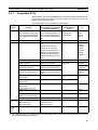
PLC Switch Settings
When the NT11 and PLC are connected to each other, set the conditions at
the PLC host link unit or the CPU as given in the table below.
The following is a general description of switch settings.
Refer to the manual for respective units for the details of the switch settings.
Item
Switch Setting
I/O port
Baud rate
RS-232C
Set the same baud rate as the NT11. (*1)
Transfer code
Parity
ASCII 7 data bits, 2 stop bits
Even
1-to-1/1-to-N
Instruction level
1-to-N (*2)
Level 1, 2, 3
Unit No.
00
*1 Set the host link baud rate up to 115,200 bps with the memory switch for
“host link baud rate”. For the details, refer to 3-7-2 Selecting the Host Link
Communication Speed (page 74).
*2 The 1-to-N setting enables BCC (Block Check Character). The 1-to-1 connection cannot be used to connect the NT11 to a host link unit.
27
Connection to a PLC by the Host Link (RS-232C Type)
Section 2-4
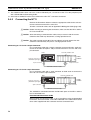
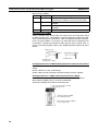
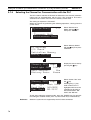
Connecting to a C-series Host Link Unit
C200H/C200HS/C200HE/HG/HX (-Z)E Rack-mounted Unit:
C200H-LK201-V1
Setting the Front Switches
Set each switch with a flat blade screwdriver so that the values or symbols in
the setting value window agree with the following.
LK201
XMT
RUN
RCV
ERROR
SW1
• Unit # (SW1, SW2)
Set these switches to 0.
SW2
0
0
5
2
SW3
• Command level, parity, and transfer code (SW4)
Set this switch to 2.
SW4
• Baud rate (SW3)
Set this switch to 5 to select 9,600 bps.
Set this switch to 6 to select 19,200 bps.
Setting the Rear Switches
ON
CTS selector switch
External
0 V (ON)
1
2
3
4
• 1-to-1/1-to-N selection (DIP switch)
Set pin 3 to ON.
• CTS selection (selector switch)
Set this always to 0 V (ON).
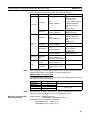
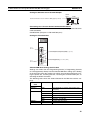
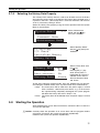
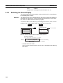
Connecting to a CVM1/CV-series Host Link Unit
CVM1/CV-series Rack-mounted Unit: CV500-LK201
A CVM1/CV-series Host Link Unit (CV500-LK201) has two connectors (communication ports 1 and 2). Either of these ports can be used for connection to
an NT11 by the RS-232C method. However, since the connectors at these
ports are of different types, a cable that matches the connector must be prepared.
• Communication port 1
Communication port 1 is a 25-pin connector for RS-232C use only.
• Communication port 2
Communication port 2 is a 9-pin connector that allows selection of the
RS-232C or RS-422A method. When this port is used with the RS-232C
method, the I/O port selector switch on the front of the Unit must be set to
RS-232C (the upper position).
28
Connection to a PLC by the Host Link (RS-232C Type)
Section 2-4
CPU Bus Unit Settings
When connecting to a CVM1/CV-series Host Link Unit, set the following communication conditions for the CPU Bus Unit settings.
Item
Setting at Host
Baud rate
Set the same baud rate as set at the NT11(*1)
Transfer code
Parity
ASCII, 7 data bits, 2 stop bits
Even
1-to-1, 1-to-N
1-to-N(*2)
Level 1, 2, 3
Command level
*1 Set the Host Link baud rate up to 115,200 bps with the memory switch at
the NT11. For details, refer to Setting the Host Link Method (page 74).
*2 The 1-to-N setting enables BCC (Block Check Character). It is not actually
possible to connect more than one NT11 in a single Host Link.
Set the CPU Bus Unit settings directly from a Programming Device (e.g.,
SYSMAC Support Software).
For details on the CPU Bus Unit settings, refer to the SYSMAC CVM1/CVseries Host Link Unit Operation Manual (W205-E1-@).
Setting the Front Switches
Communications port 1
(RS-232C)
Communications port 2
(RS-232C/RS-422A)
I/O port selector switch
RS-232C
• Unit # (SW3, SW4)
When using communication port 2, set these
switches to 0.
• I/O port selection (selector switch)
Set this to RS-232C.
• CTS selection (Pins 2 and 3)
Set pin 2 or 3 to ON. (Set this always to 0 V.)
To use communication port 1, turn ON pin 2.
To use communication port 2, turn ON pin 3.
RS-422A
• Communication condition setting (Pin 1)
Set this pin to OFF.
Communication is executed in accordance with the
CPU Bus Unit system settings made at the PLC. The
initial values for the system settings are as follows.
- Baud rate: 9,600 bps
- Parity: Even
- Xon/Xoff control: Not executed
- Communication method: Full duplex
- Stop bits: 2 stop bits
- Data length: 7 bits
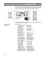
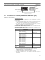
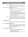
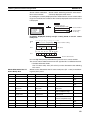
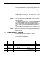
Connecting to a CS/CJ-series Serial Communications Unit
CS/CJ-series Rack-mounted Unit: CS1W-SCU21CJ-series:
CJ1W-SCU41 (Port 2 is an RS-232C Port.)
Setting the Front Switches
Set the unit number of the Serial Communications Unit by using the rotary
switch located on the front panel. Set each switch with a flat blade screwdriver
29
Connection to a PLC by the Host Link (RS-232C Type)
Section 2-4
so that the values or symbols in the setting value window agree with the following.
CS1W-SCU21
SCU21
RDY
ERH
SD2
RD2
RUN
ERC
SD1
RD1
UNIT0
No. 1
Set the unit number to 0 through F so
that it will not duplicate the numbers
used in other Units.
FE
C
CJ1W-SCU41
Set the unit number to 0 through F so
that it will not duplicate the numbers
used in other Units.
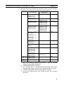
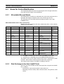
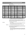
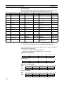
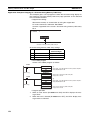
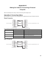
Allocation DM Area Settings for CPU Unit
Settings are written from the Programming Device (a Programming Console
or CX-Programmer) directly into the allocated DM Area (PLC Setup) of the
CPU Unit. After the settings are written, they become effective by turning the
power ON, restarting the Unit, restarting the communication port, or execution
of the STUP instruction.
The following table shows the words allocated in the DM Area and the settings.
m = DM30000 + 100 ´ unit number
Allocated DM word
Port 1
Port 2
Value
Settings
m
m+10
8000
Host Link mode, 2 stop bits, even parity, data
length 7 bits
m+1
m+11
0000
0007
Baud rate 9,600 bps
Baud rate 19,200 bps
0008
0009
Baud rate 38,400 bps
Baud rate 57,600 bps
m+2
m+12
000A
0000
Baud rate 115,200 bps
Transmit delay time 0 ms
m+3
m+13
0000
No CTS control Unit No. 0 for Host Link
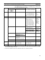
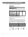
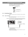
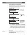
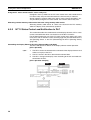
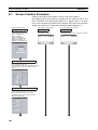
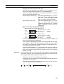
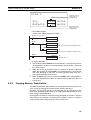
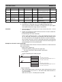
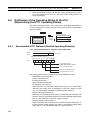
Connecting to a CPU Unit
CV-series and CVM1/CV-series (-EV@) CPU Units
CVM1-CPU01-EV2/CVM1-CPU11-EV2/CVM1-CPU21-EV2
PLC Setup
When connecting to a CVM1/CV-series CPU Unit, set the following communication conditions for the PLC Setup.
Item
Setting at Host
Baud rate
Set the same baud rate as set at the NT11(*1)
Stop bits
Parity
2 stop bits
Even
Data length
Unit #
ASCII 7 bits
00
*1 Set the Host Link baud rate at 9,600 bps with the memory switch at the
NT11. For details, refer to Setting the Host Link Method (page 74).
30
Connection to a PLC by the Host Link (RS-232C Type)
Section 2-4
Either set PLC Setup directly from a Programming Device (e.g., SYSMAC
Support Software), or transmit the PLC Setup made at a Programming Device
to the CPU Unit.
For details on the PLC Setup, refer to the SYSMAC CVM1/CV500/1000/2000
Operation Manual: Ladder Diagrams (W202-E1-@).
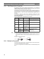
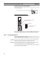
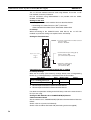
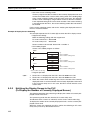
Setting the Front Switches
• Host Link Communication method
(selector switch)
Set this to RS-232C.
I/O port selector switch
RS-232C
RS-422A
• System setting (Pin 4)
To effect the existing DIP switch settings,
set SW4 to ON.
To effect the existing PLC Setup, set pin 4
to OFF.
Note
For CPU Units manufactured before or
during June 1995 (lot No. @@65), the
existing DIP switch settings differ from
the existing PLC Setup as follows.
- DIP switch settings:
2,400 bps, 1 stop bit, even parity, 7 bit
data length
- PLC Setup:
9,600 bps, 2 stop bits, even parity, 7 bit
data length
For CPU Units manufactured from July
1995 onward (lot No. @@75), the
stipulated values in the DIP switch
settings also are 9,600 bps and 2 stop
bits.
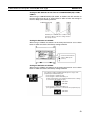
C-series C200HS, C200HX/HG/HE(-Z)E, CPM1, CPM2A, CPM2C, CQM1,
CQM1H CPU Units and SRM1
The connection method depends upon the model of PLC being used, as
shown in the following table.
PLC model
C200HS, CQM1
Connection method
Connect to the CPU Unit’s built-in RS-232C port.
C200HX/HG/HE(-Z)E
• Connect to the CPU Unit’s built-in RS-232C port.
• Connect to one of the RS-232C ports (port A or port B) on
a Serial Communications Board.
CQM1H
• Connect to the CPU Unit’s built-in RS-232C port.
• Connect to the peripheral port through a CS1W-CN118
Connecting Cable.
• Connect to the RS-232C port (port 1) on a Serial Communications Board.
CPM1
Connect to the peripheral port through a CPM1-CIF01 RS232C Adapter.
31
Connection to a PLC by the Host Link (RS-232C Type)
Section 2-4
PLC model
CPM2A, SRM1
Connection method
• Connect to the CPU Unit’s built-in RS-232C port.
• Connect to the peripheral port through a CPM1-CIF01 RS232C Adapter.
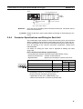
CPM2C
Connect to the CPU Unit’s RS-232C port or the peripheral
port through a Connecting Cable (CPM2C-CN111, CS1WCN118, or CS1W-CN114).
(The CPM2C-CN111 splits the Unit’s Communication Port
into a RS-232C port and a peripheral port. A CPM1-CIF01
RS-232C Adapter is also required to connect to this peripheral port.)
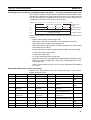
PLC Setup Settings
When connecting to a C200HS, C200HX/HG/HE(-Z)E, CPM1, CPM2A,
CPM2C, CQM1, or CQM1H CPU Unit, or SRM1, set the following communication conditions for the PLC Setup.
Item
Setting at Host
Communication mode
Baud rate
Host Link mode
Stop bits
Parity
2 stop bits
Even
Data length
Unit #
ASCII 7 bits
00
Set the same speed as set at the NT11(*1)
*1 Set the Host Link baud rate at 9,600 bps or 19,200 bps with the memory
switch at the NT11. For details, refer to Settings the Host Link Method
(page 74).
Set the PLC Setup settings directly from a Programming Device (e.g., the CXProgrammer Support Software).
For details on operations relating to the PLC Setup, refer to the manual for the
PLC which is used.
The PLC Setup area word addresses and settings to be made depending on
the Unit and port to which the connection is made are shown below.
CPM2A, CPM2C, CQM1H, or SRM1: Peripheral port connection
Word
Writing Value
DM6650
0001
DM6651
0303
0304
DM6653
32
0000
Settings
Host Link mode, no CTS control
Communication conditions set by the contents of DM
Data length 7 bits, 2 stop bits, even parity, baud rate:
9,600 bps
Data length 7 bits, 2 stop bits, even parity, baud rate:
19,200 bps
Unit # 00
Connection to a PLC by the Host Link (RS-232C Type)
Section 2-4
C200HS, C200HX/HG/HE(-Z)E, CPM2A, CPM2C, CQM1, CQM1H (other
than the CPU11), or SRM1: Built-in RS-232C port connection
Word
DM6645
DM6646
Writing Value
Settings
0001
Host Link mode, no CTS control
Communication conditions set by the contents of DM
0303
Data length 7 bits, 2 stop bits, even parity, baud rate:
9,600 bps
0304
Data length 7 bits, 2 stop bits, even parity, baud rate:
19,200 bps
DM6648
0000
Unit # 00
C200HX/HG/HE(-Z)E: Serial Communications Board port A
CQM1H: Serial Communications Board port 1
Word
DM6555
DM6556
DM6558
Writing Value
Settings
0001
Host Link mode, no CTS control
Communication conditions set by the contents of DM
0303
Data length 7 bits, 2 stop bits, even parity, baud rate:
9,600 bps
0304
Data length 7 bits, 2 stop bits, even parity, baud rate:
19,200 bps
0000
Unit # 00
C200HX/HG/HE(Z)E: Serial Communications Board port B
Word
DM6550
Writing Value
Settings
0001
Host Link mode, no CTS control
Communication conditions set by the contents of DM
DM6551
0303
Data length 7 bits, 2 stop bits, even parity, baud rate:
9,600 bps
0304
Data length 7 bits, 2 stop bits, even parity, baud rate:
19,200 bps
0000
Unit # 00
DM6553
CPM1: Peripheral port connection through a CPM1-CIF01 RS-232C Adapter
Word
DM6650
Writing Value
Settings
0001
Host Link mode
Communication conditions set by the contents of DM
DM6651
0303
Data length 7 bits, 2 stop bits, even parity, baud rate:
9,600 bps
0304
Data length 7 bits, 2 stop bits, even parity, baud rate:
19,200 bps
0000
Unit # 00
DM6653
Connecting to a CPM2C
The CPM2C PLCs do not have the same kind of port connectors found on
CS1-series PLCs. The CPM2C’s communication port handles both RS-232C
and peripheral port connections, which are divided internally. Therefore, when
using the CPM2C, it is necessary to select RS-232C or peripheral port connections, according to the kind of cable and port (on the cable) used, as
shown in the following table. Refer to the CPM2C Operation Manual for more
details.
33
Connection to a PLC by the Host Link (RS-232C Type)
Section 2-4
Port connecting to PT
PLC Setup
RS-232C port (D-Sub 9-pin) of CPM2C-CN111
Peripheral port of CPM2C-CN111
Built-in RS-232C port settings
Peripheral port settings
RS-232C port (D-Sub 9-pin) of CS1W-CN118
Peripheral port of CS1W-CN114
Built-in RS-232C port settings
Peripheral port settings
Peripheral port
CPM2C-CN111
CPM2C
RS-232C port
(D-Sub 9-pin, female)
CS1W-CN118
CPM2C
RS-232C port
(D-Sub 9-pin, female)
CS1W-CN114
CPM2C
Peripheral port
Setting the DIP Switches of a C200HX/HG/HE(-Z)E, CQM1, or CQM1H
When using a C200HX/HG/HE(-Z)E, CQM1, or CQM1H, the DIP switches on
the front panel must be set as shown below in order to make the settings in
the PLC Setup (in the DM Area) effective.
C200HX/HG/HE(-Z)E
CQM1
CQM1H
RS-232C port communication condition setting
Set pin 5 to OFF to make the settings made in
PLC Setup effective.
When using the CQM1H’s built-in peripheral port, turn ON SW7.
Setting the Switches of a CPM2A
When using a CPM2A, the switches on the front panel must be set as shown
below in order to make the PLC Setup settings effective.
Set the Communications
switch to OFF (down
position).
Setting the Switches of a CPM2C
When using a CPM2C, the switches on the front panel must be set as shown
below in order to make the PLC Setup settings effective.
34
Connection to a PLC by the Host Link (RS-232C Type)
Section 2-4
The settings for SW1 and SW2 depend upon the usage of the
peripheral port and RS-232C port.
• Connecting PT to peripheral port
• Connecting PT to built-in RS-232C port
(A device that requires non-standard communications settings
is connected to the peripheral port.)
SW1: OFF
SW2: ON
• Connecting PT to built-in RS-232C port
(A Programming Console is connected to the peripheral port.)
SW1: OFF
SW2: OFF
Setting the Switches on an RS-232C Adapter
When using a CPM1-CIF01 RS-232C Adapter, set the mode switch as shown
in the following diagram.
CPM1CIF01
CPM1
Set the mode setting switch to HOST (upper position).
CS/CJ-series CPU Unit model: CS1G/HCPU@@-E (-V1)
CS1G/H-CPU@@H
CJ1G-CPU@@
Connect to the built-in RS-232C port of the CPU Unit, or the RS-232C port of
the Communication Board. Note that the connection to a peripheral port must
be made via an RS-232C Adapter (CS1W-CN118) specially designed for connecting to a peripheral port.
PLC Setup
When connecting to a CS/CJ-series CPU Unit, set the following communication conditions for the PLC Setup. Since the settings shown below are the
PLC default settings for the CPU Unit, no change to the PLC Setup is necessary as long as the baud rate is maintained at 9,600 bps.
Item
Baud rate
Setting at Host
Stop bits
Set the same speed as set at the NT11(*1)
2 stop bits
Parity
Data length
Even
ASCII 7 bits
Unit No. for the Host Link
00
*1 Set the Host Link baud rate up to 115,200 bps with the memory switch at
the NT11. For details, refer to Settings the Host Link Method (page 74).
When the baud rate is set to 19,200 bps, the PLC Setup of the CPU Unit
need to be changed.
Either set the PLC Setup directly from a Programming Device (Programming
Console), or transmit the PLC Setup made at a Programming Device (CXProgrammer) to the CPU Unit.
35
Connection to a PLC by the Host Link (RS-232C Type)
Section 2-4
For details on PLC Setup, refer to the SYSMAC CS Series Operation Manual
(W339-E1-@) or SYSMAC CJ Series Operation Manual (W393-E1-@).
When using the built-in RS-232C port of a CS1G/H, CS1G/H-H, or CJ1G
Word address
CIO 160
8000
CIO 161
0000
Settings
Host Link mode, data length 7 bits,
2 stop bits, even parity
Baud rate: 9,600 bps.
0007
0008
Baud rate: 19,200 bps.
Baud rate: 38,400 bps.
0009
000A
Baud rate: 57,600 bps.
Baud rate: 115,200 bps.
0000
Unit #00
CIO 166
Writing Value
When using the peripheral port of a CS1G/H, CS1G/H-H, or CJ1G
Word address
CIO 144
CIO 145
CIO 150
36
Writing Value
8000
Settings
Host Link mode, data length 7 bits,
2 stop bits, even parity
0000
0007
Baud rate: 9,600 bps.
Baud rate: 19,200 bps.
0008
0009
Baud rate: 38,400 bps.
Baud rate: 57,600 bps.
000A
0000
Baud rate: 115,200 bps.
Unit #00
Connection to a PLC by the Host Link (RS-232C Type)
Section 2-4
Setting the Front Switches
Set pins 4 and 5 of the CPU Unit DIP switch in accordance with the port that
the NT11 is connected to.
CS1G/H, CS1G/H-H
RUN
ERR/ALM
INH
PRPHL/COMM
SYSMAC
CS1G
PROGRAMMABLE CONTROLLER
CPU42
OPEN
Peripheral port
This is used mainly for
connection to the
Programming Device.
(This also supports the
RS-232C Unit connection.)
MCPWR
OPEN
BUSY
DIP switches (inside the battery storage)
• Set pin 4 to ON (establishing communication in accordance with PLC Setup) when connecting the
NT11 to the peripheral port.
• Set pin 5 to OFF (establishing communication in accordance with PLC Setup) when connecting the
NT11 to the RS-232C port.
PERIPHERAL
RS-232C port
This is used mainly for
connection to the
RS-232C Unit.
(This also supports a
CX-Programmer
connection.)
PORT
CJ1G
Peripheral port
This is used mainly for connection
to the Programming Device.
(This also supports the RS-232C
Unit connection.)
DIP switches (inside the battery storage)
• Set pin 4 to ON (establishing communication in accordance with PLC Setup) when connecting the
NT11 to the peripheral port.
• Set pin 5 to OFF (establishing communication in accordance with PLC Setup) when connecting the
NT11 to the RS-232C port.
RS-232 port
This is used mainly for connection to the RS-232C
Unit.
(This also supports a CX-Programmer connection.)
Connecting to CS-series Serial Communications Board
Serial Communications Board equipped with a RS-232C port for CS-series
CPU Units: CS1W-SCB41/21
Allocation DM Area Settings for CPU Unit
Settings are written from the Programming Device (a Programming Console
or CX-Programmer) directly into the allocated DM Area (PLC Setup) of the
CPU Unit. After the settings are written, they become effective by turning the
power ON, restarting the Unit, restarting the communication port, or execution
of the STUP instruction.
37
Connection to a PLC by the Host Link (RS-422A Type)
Section 2-5
The following table shows the words allocated in the DM Area and the settings.
Allocated DM word
Port 1
Port 2
Settings
DM32000
DM32010
8000
DM32001
DM32011
0000
Host Link mode, 2 stop bits, even parity, data
length 7 bits
Baud rate 9,600 bps.
0007
0008
Baud rate 19,200 bps.
Baud rate: 38,400 bps.
0009
000A
Baud rate: 57,600 bps.
Baud rate: 115,200 bps.
0000
0000
Transmit delay time 0 ms.
No CTS control Unit No. 0 for Host Link
DM32002
DM32003
2-5
Value
DM32012
DM32013
Connection to a PLC by the Host Link (RS-422A Type)
Connect the NT11 to an OMRON PLC by using the RS-422A type host link
method.
If the distance between the NT11 and the PLC is greater than 15 m, this
method should be used. The maximum distance over which a connection can
be made is 500 m.
when using the RS-422A method, the host computer and PLC are usually
connected in a 1 to N ratio (more than one PLC), but in the special case of the
connection between the NT11 and PLC, the ratio is 1 to 1.
In order to make a connection to the PLC using the host link method (RS422A type), the “Comm. Type” memory switch of the NT11 must be set to the
host link, and the “Comm. Port” memory switch must be set to RS-422A. For
details on memory switch settings, refer to 3-7-1 Selecting the Host Communication Method (page 73).
2-5-1
Compatible PLCs
When Using the Host Link Method
Compatible Host Units
Some models and series of OMRON PLCs have the RS-422A type Host Link
function built in. With a CS series, CJ series, and CQM1H Board or Unit, and
CQM1H, the Host Link method can be used by installing a Serial Communications Board. In addition, some C200HX/HG/HE(-Z)E devices have an integral
CPU Unit that can be connected in the Host Link method by installing a Serial
Communications Board.
With the CPM2A and CPM2C, an RS-422A type of 1:1 NT Link can be connected through a CPM1-CIF11 RS-422A Adapter.
Check the model and series of the PLC and the type of the installed Board or
Unit before making a connection.
38
Connection to a PLC by the Host Link (RS-422A Type)
Section 2-5
The following table lists the Units that are equipped with an RS-422A Host
Link function compatible with the NT11.
PLC
Series
Units with Built-in Host Link Function
Host Link Unit/
CPU Unit
Serial
Communications
Board
CS Series
CS1W-SCB41-E
---
CJ Series
CJ1W-SCU41
---
C Series
C200H-LK202-V1
---
C200HW-COM03/06EV1
---
---
CPM1-10/20/30CDR-@
+CPM1-CIF11
CPM1A-10/20/30/40CD@-@
+CPM1-CIF11
CPM2A-30/40/60CD@-@
+CPM1-CIF11
(Peripheral port connection)
SRM1
Connectable
to
CS1G-CPU42/43/44/45-EV1
CS1H-CPU63/64/65/66/67-EV1
CS1G-CPU42H/43H/44H/45H
CS1H-CPU63H/64H/65H/66H/
67H
CJ1G-CPU44/45
CS1G
CS1H
CS1G-H
CS1H-H
C200HS-CPU01/03/21/23/31/
33-E
C200HS-CPU01/21-EC
C200HE-CPU11/32/42-E
C200HE-CPU11/32/42-ZE
C200HG-CPU33/43/53/63-E
C200HG-CPU33/43/53/63-ZE
C200HX-CPU34/44/54/64-E
C200HX-CPU34/44/54/64/65/
85-ZE
C200HE-CPU32/42-E
C200HE-CPU32/42-ZE
C200HG-CPU33/43/53/63-E
C200HG-CPU33/43/53/63-ZE
C200HX-CPU34/44/54/64-E
C200HX-CPU34/44/54/64/65/
85-ZE
---
C200HS
C200HE
C200HE-ZE
C200HG
C200HG-ZE
C200HX
C200HX-ZE
CPM1
---
CPM2A
---
CPM2C-10/20@@@@@@-@ (*1) ---
CPM2C
CQM1H-SCB41
CV500-LK201
--CVM1-CPU01-EV2
CVM1-CPU11-EV2
CVM1-CPU21-EV2
SRM1-C02-V1+CPM1-CIF11
CQM1H
CVM1
---
CVM1
Series (*2)
CPU Units Connectable with
Host Link Units or Expansion
Serial Communications Board
---
CQM1H-CPU51/61
CVM1-CPU01-EV2
CVM1-CPU11-EV2
CVM1-CPU21-EV2
---
CJ1G
C200HE
C200HE-ZE
C200HG
C200HG-ZE
C200HX
C200HX-ZE
SRM1
*1 Use a CPM2C-CN111 or CS1W-CN114/118 Connecting Cable, CPM1-CIF01 RS-232C Adapter, or CPM1CIF11 RS-422A Adapter to connect.
*2 CPU Units of CVM1/CV-series PLCs without the suffix -EV@ cannot be connected.
39
Connection to a PLC by the Host Link (RS-422A Type)
2-5-2
Section 2-5
Parts Required for Connection
The RS-422A cable used for RS-422A communications is not supplied by
OMRON. Make this cable in accordance with the environment (PLC used and
transmission distance between the NT11 and PLC).
One connector, one connector cover and one cable are required to make up a
connecting cable. One connector and one connector cover is supplied with
the PLC. However, a cable of the type recommended by OMRON must be
prepared.
For details on making the cable, refer to Appendix D Making the Cable
(page 153). The table below lists the components supplied with each unit and
the recommended cables.
Check the required parts and prepare them in advance.
Note
Name
Connector
set
Model
XM2S-0911S003
Maker
OMRON
Remarks
9-pin connector
Connector and Connector hood
Connector
XM2A-0901
Connector
hood
XM2S-0911
Connector
set
XM2S-0911S003
9-pin connector
Made by OMRON
9-pin connector
Made by OMRON
9-pin
Made by OMRON,
connector and
hood included
Cable
TKVVBS4P-03
Crimp terminals
1.25-N3A
(fork type)
Y1.25-3.5L
(fork type)
Tachii Electric Wire
Co., Ltd.
Japan Solderless Recommended cable size:
Terminal MFG
AWG22 to 18
Molex Inc.
(0.3 to 0.75 mm2)
1. Always use crimp terminals for wiring.
2. Before connecting or disconnecting cables between devices, make sure
that the power supply to all of the connected devices (NT11, PLC, etc.) is
OFF.
Examples of applicable terminals
Round type
Fork type
6.2 mm or less
2-5-3
6.2 mm or less
Method for Connection
For RS-422A type communication, an RS-422A cable is used as the transmission channel connecting the NT11 and PLC.
As shown in the figure below, the RS-422A cable is connected directly to the
NT11.
40
Connection to a PLC by the Host Link (RS-422A Type)
NT11
Section 2-5
Host link unit/CPU unit
C200H,
C200HS
RS-422A terminal
block
9-pin connector
RS-422A connector cable
(max. cable length : 500 m)
Reference
Carry out class 3 grounding at the FG terminal of the PLC. For details, refer to
the manual for the PLC.
!Caution Switch off the NT11 power supply before connecting or disconnecting a connector.
2-5-4
Connector Specifications and Wiring for Each Unit
The combination of pin numbers to which the connecting wires are connected
differs according to the connector specifications for each unit. Check the connector specifications of the unit to be connected and make the wiring connections by referring to the relevant connection combination among those
indicated below.
For details on making the cable, refer to Appendix D Making the Cable
(page 153).
[NT11 RS-422A terminal block specifications]
- Connected terminal block: RS-422A terminal block (M3.5 screws)
- Electrical characteristics: Conform to EIA RS-422A
- Signal direction:
Signal Name
Signal input and output is relative to the NT11
Abbreviation
Signal Direction
Input
SDA SDB RDA RDB
Send data A
SDA (SD–)
Send data B
Receive data A
SDB (SD+)
RDA (RD–)
❍
Receive data B
RDB (RD+)
❍
Output
❍
❍
• Connecting an NT11 to a C-series host link unit
[C-series host link connector specifications]
- Applicable host link units: C200H-LK202 (-V1)
- Electrical characteristics: Conform to EIA RS-422A
41
Connection to a PLC by the Host Link (RS-422A Type)
Section 2-5
- Signal direction: Signal input and output is relative to the host link unit.
1
5
Connector
Pin No.
6
9
Signal Name
Abbreviation
Signal Direction
Input
Output
1
3
Receive data B
Signal ground
RDB
SG
❍
–
5
6
Send data B
Receive data A
SDB
RDA
❍
7
9
Frame ground
Send data A
FG
SDA
–
❍
–
–
❍
[Wiring connections]
PLC (host link unit)
Shielding wire
Pin
number
NT11
1
3
5
6
7
9
Abbreviation
RS-422A
terminal
block
Abbreviation
SDA (−)
SDB (+)
RDA (−)
RDB (+)
Connector cover
RDB (+)
SG
SDB (+)
RDA (−)
FG
SDA (−)
FG
RS-422A
interface
RS-422A cable
2-5-5
PLC Switch Settings
When the NT11 and PLC are connected to each other, set the conditions at
the PLC host link unit or the CPU as given in the table below.
The following is a general description of switch settings.
Refer to the manual for respective units for the details of the switch settings.
Item
Switch Setting
I/O port
RS-422A
Baud rate
Transfer code
Set the same baud rate as the NT11
ASCII 7 data bits, 2 stop bits
Parity
1-to-1/1-to-N
Even
1-to-N (*1)
Instruction level
Unit No.
Level 1, 2, 3
00
*1: The 1-to-N setting enables BCC (Block Check Character). It is not possible to connect more than one NT11 in a single host link.
Connecting to a C-series Host Link Unit
C200H/C200HS/C200HE(-Z)E/C200HG(-Z)E/C200HX(-Z)E
Rack-mounting model: C200H-LK201-V1
Setting the Front Switches
Set each switch with a flat blade screwdriver so that the values or symbols in
the setting value window agree with the following:
42
Connection to a PLC by the Host Link (RS-422A Type)
Section 2-5
LK201
XMT
RUN
RCV
ERROR
SW1
• Unit # (SW1, SW2)
Set these switches to 0.
SW2
0
0
5
2
SW3
SW4
• Command level, parity, and transfer code (SW4)
Set this switch to 2.
• Baud rate (SW3)
Set this switch to 5 to select 9,600 bps.
Set this switch to 6 to select 19,200 bps.
Setting the Rear Switches
• Terminator setting (selector switch)
Set this switch to ON.
Terminator
1-to-1 (ON)
ON
1-to-N (OFF)
OFF
• 1-to-1/1-to-N protocol selection (selector switch)
Set this switch to 1-to-N (OFF).
Connecting to a CVM1/CV-series Host Link Unit
CVM1/CV-series Rack-mounting model: CV500-LK201
A CVM1/CV-series Host Link Unit (CV500-LK201) has two connectors (communication ports 1 and 2). To use the RS-422A type Host Link method, set
communication port 2 to RS-422A.
Communication port 2 is a 9-pin connector that allows selection of the RS232C or RS-422A method. When this port is used with the RS-422A method,
the I/O port selector switch on the front of the Unit must be set to RS-422A
(the lower position).
CPU Bus Unit Settings
When connecting to a CVM1/CV-series Host Link Unit, set the following communication conditions for the CPU Bus Unit settings.
Item
Setting at Host
Baud rate
Set the same speed as for the NT11. (*1)
Transfer code
Parity
ASCII, 7 data bits, 2 stop bits
Even
1-to-1/1-to-N
1-to-N(*2)
Level 1, 2, 3
Command level
*1 Set the Host Link baud rate at 9,600 bps or 19,200 bps with the Comm.
Speed memory switch at the NT11. For details, refer to Setting the Host
Link Method (page 74).
*2 The 1-to-N setting enables BCC (Block Check Character). It is not actually
possible to connect more than one NT11 in a single Host Link.
43
Connection to a PLC by the Host Link (RS-422A Type)
Section 2-5
Set the CPU Bus Unit settings directly from a Programming Device (e.g.,
SYSMAC Support Software).
For details on the CPU Bus Unit settings, refer to the SYSMAC CVM1/CVseries Host Link Unit Operation Manual (W205-E1-@).
Setting the Front Switches
• Unit # (SW3, SW4)
Set these switches to 0.
Communications port 1
(RS-232C)
Communications port 2
(RS-232C/RS-422A)
I/O port selector switch
RS-232C
• I/O port selection (selector switch)
Set this to RS-422A.
RS-422A
• Communication condition setting (pin 1)
Set this pin to OFF.
Communication is executed in accordance with the
CPU Bus Unit system settings made at the PLC. The
initial values for the system settings are as follows.
- Baud rate: 9,600 bps
- Parity: Even
- Xon/Xoff control: Not executed
- Communication method: Full duplex
- Stop bits: 2 stop bits
- Data length: 7 bits
• Terminating resistance setting (selector switch)
Set this to ON.
Connecting to a CJ-series Serial Communications Unit
CJ-series: CJ1W-SCU41 (Port 1 is an RS-422A/485 port.)
Setting the Front Switches
Set the unit number of the Serial Communications Unit with the rotary switch
on the front of the Unit. Set the unit number with a flat blade screwdriver. Also,
set the communications mode switch to select 4-wire (RS-422A) communications and turn ON the terminator switch to enable the terminating resistance.
Terminator switch
Turn ON to connect the terminator.
(Set terminator ON.)
Communications mode switch
Set the 2-wire/4-wire selector switch to
"4" to select 4-wire (RS-422A)
communications.
Unit number switch
Set the unit number between 0 and F
so that it will not duplicate the
numbers used in other Units.
Allocation DM Area Settings for CPU Unit
Settings are written from the Programming Device (a Programming Console
or CX Programmer) directly into the allocated DM Area (PLC Setup) of the
44
Connection to a PLC by the Host Link (RS-422A Type)
Section 2-5
CPU Unit. After the settings are written, they become effective by turning the
power ON, restarting the Unit, restarting the communication port, or execution
of the STUP instruction.
The following table shows the words allocated in the DM Area and the settings.
m = DM30000 + 100 ´ unit number
Allocated DM word
Port 1
Value
Settings
m
8000
m+1
0000
Host Link mode, 2 stop bits, even parity, data
length 7 bits
Baud rate 9,600 bps.
0007
0008
Baud rate 19,200 bps.
Baud rate: 38,400 bps.
0009
000A
Baud rate: 57,600 bps.
Baud rate: 115,200 bps.
0000
0000
Transmit delay time 0 ms.
No CTS control Unit No. 0 for Host Link
m+2
m+3
Connecting to a CPU Unit
CVM1/CV-series (-EV@) CPU Units
CVM1-CPU01-EV2/CVM1-CPU11-EV2/CVM1-CPU21-EV2
PLC Setup
When connecting to a CVM1/CV-series CPU Unit, set the following communication conditions for the PLC Setup.
Item
Setting at Host
Baud rate
Set the same baud rate as for the NT11. (*1)
Stop bits
Parity
2 stop bits
Even
Data length
Unit #
ASCII 7 bits
00
*1 Set the Host Link baud rate at 9,600 bps or 19,200 bps with the Comm.
Speed memory switch at the NT11. For details, refer to Setting the Host
Link Method (page 74).
Set the PLC Setup directly from a Programming Device (e.g., SYSMAC Support Software).
For details on the PLC Setup, refer to the SYSMAC CVM1/CV500/CV1000/
CV2000 Operation Manual: Ladder Diagrams (W202-E1-@).
45
Connection to a PLC by the Host Link (RS-422A Type)
Section 2-5
Setting the Front Switches
• Host Link communication method
selection (selector switch)
Set this to RS-422A.
• Communications type setting (pin 3)
Set pin 3 to OFF.
(for Host Link communication)
I/O port selector switch
RS-232C
RS-422A
• Host Link default value settings
(pin 4)
To effect the existing DIP switch settings,
set pin 4 to ON.
To effect the values set in the PLC
Setup, set pin 4 to OFF.
Note
For CPU Units manufactured before or
during June 1995 (lot No. @@65), the
existing DIP switch settings differ from
the PLC Setup default values as follows.
- Existing DIP switch settings:
2,400 bps, 1 stop bit, even parity, 7 bit
data length
- PLC Setup default values:
9,600 bps, 2 stop bits, even parity, 7 bit
data length
For CPU Units manufactured from July
1995 onward (lot No. @@75), the
stipulated values in the DIP switch
settings also are 9,600 bps and 2 stop
bits.
• Terminator setting (pin 6)
Set this switch to ON.
(Set terminator ON.)
C200HX/HG/HE(-Z)E, CPM1, CPM2A, CPM2C, CQM1H, or SRM1
The connection method depends upon the model of PLC being used, as
shown in the following table.
PLC model
C200HX/HG/HE(-Z)E
CQM1H
Connection method
• Connect to the RS-422A port (port A) on a Serial Communications Board.
• Connect to the RS-422A port (port 2) on a Serial Communications Board.
CPM1
• Connect to the peripheral port through a CPM1-CIF11 RS422A Adapter.
CPM2A, SRM1
• Connect to the peripheral port through a CPM1-CIF11 RS422A Adapter.
CPM2C
• Connect to the peripheral port (on a CPM2C-CN111 or
CS1W-CN114 Connecting Cable) through a CPM1-CIF11
RS-422A Adapter.
(The CPM2C-CN111 splits the Unit’s Communication Port
into a RS-232C port and a peripheral port.)
Reference
• There are no Serial Communications Boards for the C200HX/HG/HE(-Z)E
in which port B is the RS-422A port.
• There are no Serial Communications Boards for the CQM1H in which port
1 is the RS-422A port.
46
Connection to a PLC by the Host Link (RS-422A Type)
Section 2-5
PLC Setup Settings
When connecting to a C200HX/HG/HE(-Z)E or CPM1, CPM2A, CPM2C,
CQM1H CPU Units or SRM1, set the following communication conditions for
the PLC Setup.
Item
Setting at Host
I/O port
RS-422A
Communication mode
Baud rate
Host Link mode
Stop bits
Parity
2 stop bits
Even
Data length
Unit #
ASCII 7 bits
00
Set the same baud rate as for the NT11. (*1)
*1 Set the Host Link baud rate at 9,600 bps or 19,200 bps with the Comm.
Speed at the NT11. For details, refer to Setting the Host Link Method
(page 74).
Set the PLC Setup settings directly from a Programming Device (e.g., CXProgrammer).
For details on operations relating to the PLC Setup, refer to the manual for the
PLC that is used.
The PLC Setup addresses and settings to be made depending on the Unit to
which the connection is made are shown below.
When using port A of the Serial Communications Board of C200HX/HG/HE(Z)E
Word
Writing Value
Settings
DM6555
0001
Host Link mode, no CTS control
Communication conditions set by the contents of DM
DM6556
0303
Data length 7 bits, 2 stop bits, even parity, baud rate:
9,600 bps
0304
Data length 7 bits, 2 stop bits, even parity, baud rate:
19,200 bps
Unit # 00
DM6558
0000
When using a CPM1, CPM2A, CPM2C, SRM1
Word
Writing Value
Settings
DM6650
0001
Host Link mode, no CTS control
Communication conditions set by the contents of DM
DM6651
0303
Data length 7 bits, 2 stop bits, even parity, baud rate:
9,600 bps
Data length 7 bits, 2 stop bits, even parity, baud rate:
19,200 bps
Unit # 00
0304
DM6653
0000
47
Connection to a PLC by the Host Link (RS-422A Type)
Section 2-5
When using a CQM1H
Word
DM6550
DM6551
Writing Value
Settings
0001
Host Link mode, no CTS control
Communication conditions set by the contents of DM
0303
Data length 7 bits, 2 stop bits, even parity, baud rate:
9,600 bps
0304
Data length 7 bits, 2 stop bits, even parity, baud rate:
19,200 bps
DM6553
0000
Unit # 00
Connecting to a CPM2C
Only the CPM2C PLCs do not have the same kind of port connectors found
on CS/CJ-series PLCs. The CPM2C’s communication port handles both RS232C and peripheral port connections, which are divided internally. Therefore,
when using the CPM2C, it is necessary to select RS-232C or peripheral port
connections, according to the kind of cable and port (on the cable) used, as
shown in the following table. Refer to the CPM2C Operation Manual for more
details.
Peripheral port
CPM2C-CN111
CPM2C
CS1W-CN114 CPM2C
Peripheral port
RS-232C port
(D-Sub 9-pin, female)
Setting Switches on a C200HX/HG/HE(-Z)E Serial Communications Board
Set the switches on a C200HX/HG/HE(-Z)E Serial Communications Board as
follows.
Switch 1:Set to 4 (4-wire, for RS-422A)
Switch 2:Set to ON for terminator ON (terminating resistance applied)
Setting Switches on a CQM1H Serial Communications Board
Set the switches on a CQM1H Serial Communications Board as follows.
Wire selection (WIRE): Set to 4 (4-wire, for RS-422A)
Terminator (TERM): Set to ON for termination ON.
Serial Communications Board
(Inner Board slot 1)
Terminator Switch (TERM)
Set to ON (right side).
Wire Selection Switch (WIRE)
Set to 4 (right side).
48
Connection to a PLC by the Host Link (RS-422A Type)
Section 2-5
Setting the Switches on an RS-422A Adapter
CPM1CIF11
CPM1
Set the terminator selector switch to ON (upper position).
Connecting to a CS-series Serial Communications Board
Serial Communications Board with RS-422A/485 port equipped for CS-series
CPU Unit Model:
CS1W-SCB41 (The port 2 is RS-422A/485 port.)
Setting the Front Switches
RDY
COMM1
COMM2
Port 1
RS-232C
PORT1
Terminal resistance setting switch (TERM)
Set to ON (Terminal resistance is present.) (right side)
OFF
2
Port 2
RS-422A/485
ON TERM
4
WIRE
PORT2
(RS422/
RS485)
Two-wire/four-wire changeover switch (WIRE)
4 (4-wire) (right side)
SCB41
Allocated DM Area Settings for CPU Unit
Settings are written from the Programming Device (a Programming Console
or CX-Programmer) directly into the allocated DM Area settings (PLC Setup)
of the CPU Unit. After the settings are written, they become effective by turning the power ON, restarting the Unit, restarting the communication port, or
executing the STUP instruction.
The following table shows the words allocated in the DM Area and the settings.
Allocated DM
word
Port 2
Value
Settings
DM32010
8000
DM32011
0000
Host Link mode, 2 stop bits, data length 7 bits,
even parity,
Baud rate 9,600 bps.
0007
0008
Baud rate 19,200 bps.
Baud rate: 38,400 bps.
0009
000A
Baud rate: 57,600 bps.
Baud rate: 115,200 bps.
0000
0000
Transmit delay time 0 ms.
No CTS control Unit No. 0 for Host Link
DM32012
DM32013
49
Connection to a PLC by the NT Link (RS-232C Type)
2-6
Section 2-6
Connection to a PLC by the NT Link (RS-232C Type)
Connect the NT11 to an OMRON PLC by the NT link method.
To connect the NT11 to a PLC by the NT link method, the NT11 memory
switch for “host communication” must be set for the NT link. For the “host
communication” setting, refer to 3-7-1 Selecting the Host Communication
Method (page 73).
2-6-1
Compatible PLCs
Some models and series of OMRON PLCs have the host link function built in.
Check the model and series of the PLC against the type of host link unit
before marking the connections.
The compatible PLCs are listed in the table below.
Using the 1:1 NT Link
Compatible Host Units
Some models and series of OMRON PLCs have the 1:1 NT Link function built
in. With CQM1H PLCs, a Serial Communications Board can be added to provide 1:1 NT Link communications. Some C200HX/HG/HE(-Z)E CPU Units
can be connected by the 1:1 NT Link by installing a Communication Board.
Check the model and series of the PLC against the model of CPU Unit before
making the connections.
50
Connection to a PLC by the NT Link (RS-232C Type)
Section 2-6
The hosts that can be connected to the NT11 by the 1:1 NT Link using the
RS-232C ports of both Units are indicated in the table below.
PLC Series
C Series
CPU Units with Built-in
NT Link Function
CPU Units Connectable
with Expansion
Communication Board(*1)
Connectable to
C200HS-CPU21-E, -EC
C200HS-CPU23-E
C200HS-CPU31-E
C200HS-CPU33-E
---
C200HS
C200HE-CPU42-(Z)E
C200HE-CPU32-(Z)E
C200HE-CPU42-(Z)E
C200HE (-Z)E
C200HG-CPU43-(Z)E
C200HG-CPU63-(Z)E
C200HG-CPU33-(Z)E
C200HG-CPU43-(Z)E
C200HG-CPU53-(Z)E
C200HG-CPU63-(Z)E
C200HG (-Z)E
C200HX-CPU44-(Z)E
C200HX-CPU64-(Z)E
X200HX-CPU65-ZE
C200HX-CPU85-ZE
C200HX-CPU34-(Z)E
C200HX-CPU44-(Z)E
C200HX-CPU54-(Z)E
C200HX-CPU64-(Z)E
C200HX-CPU65-ZE
C200HX-CPU85-ZE
C200HX (-Z)E
CPM1-10CDR-@ (*2)
---
CPM1
CPM2A-30CD@@-@
CPM2A-40CD@@-@
CPM2A-60CD@@-@
---
CPM2A
CPM2C-10@@@@@@-@
---
CPM2C
CQM1-CPU41-EV1
CQM1-CPU42-EV1
CQM1-CPU43-EV1
CQM1-CPU44-EV1
CQM1-CPU45-EV1
---
CQM1
CQM1H-CPU21-E
CQM1H-CPU51-E
CQM1H-CPU61-E
CQM1H-CPU51 (*4)
CVM1-CPU01-EV2
CVM1-CPU11-EV2
CVM1-CPU21-EV2
---
CVM1
SRM1-C02-V2
---
SRM1
CPM1-20CDR-@ (*2)
CPM1-30CDR-@ (*2)
CPM1A-10CD@-@ (*2)
CPM1A-20CD@-@ (*2)
CPM1A-30CD@-@ (*2)
CPM1A-40CD@-@ (*2)
(*3)
CPM2C-20@@@@@@-@
CVM1 Series
(*5)
CompoBus/S
Master Unit
CQM1H-CPU61
CQM1H
(*4)
*1 One of the following Communication Boards is required: C200HWCOM02/COM04/COM05/COM06-EV1.
*2 A CPM1-CIF01 adapter is required.
*3 Use a CPM2C-CN111 or CS1W-CN114/118 Connecting Cable, CPM1CIF01 RS-232C Adapter, or CPM1-CIF11 RS-422A Adapter to connect.
*4 A CQM1H-SCB41 Serial Communications Board is required.
*5 CPU Units of CVM1/CV-series PLCs without the suffix -EV@ cannot be
connected.
51
Connection to a PLC by the NT Link (RS-232C Type)
Reference
Section 2-6
CS/CJ-series CPU Unit cannot be connected with the 1:1 connection NT link
method. Use the Host Link method (up to 115,200 bps).
Settings at The Host
The setting methods for each Unit are as follows:
Connecting to a C-series C200HS, C200HX/HG/HE(-Z)E, CPM1, CPM2A,
CPM2C, CQM1, CQM1H, or SRM1
PLC Setup Settings
Write the PLC Setup (in the DM Area) settings directly from a Programming
Device (e.g., SYSMAC Support Software) in accordance with the host model
and port.
Host Model
RS-232C port of C200HS, C200HX/
HG/HE(-Z)E, CPM2A, CPM2C,
CQM1, CQM1H, SRM1
Word
DM6645
Port A of C200HX/HG/HE(-Z)E (*1)
DM6555
Writing Value
Setting
4000
Use 1:1 NT
Link
Port 1 of CQM1H (*2)
Port B of C200HX/HG/HE(-Z)E (*1)
DM6550
CPM1
DM6650
*1 RS-232C port of the Communication Board
*2 RS-232C port of the Serial Communications Board
For details on operations relating to the PLC Setup, refer to the manual for the
PLC that is used.
Connecting to a CPM2C
The CPM2C PLCs do not have the same kind of port connectors found on CS/
CJ-series PLCs. The CPM2C’s communication port handles both RS-232C
and peripheral port connections, which are divided internally. Therefore, when
using the CPM2C, it is necessary to select RS-232C or peripheral port connections, according to the kind of cable and port (on the cable) used, as
shown in the following table. Refer to the CPM2C Operation Manual for more
details.
Port connecting to PT
RS-232C port (D-Sub 9-pin) of CPM2C-CN111
PLC Setup
Built-in RS-232C port settings
Peripheral port of CPM2C-CN111
RS-232C port (D-Sub 9-pin) of CS1W-CN118
Peripheral port settings
Built-in RS-232C port settings
Peripheral port of CS1W-CN114
Peripheral port settings
Peripheral port
CPM2C-CN111
CPM2C
RS-232C port
(D-Sub 9-pin, female)
52
CS1W-CN118
CPM2C
RS-232C port
(D-Sub 9-pin, female)
CS1W-CN114
Peripheral port
CPM2C
Connection to a PLC by the NT Link (RS-232C Type)
Section 2-6
Setting the DIP Switches on the Front of a C200HX/HG/HE(-Z)E, CQM1,
CQM1H
When using a C200HX/HG/HE(-Z)E, CQM1, or CQM1H, the DIP switches on
the front panel must be set as shown below in order to make the settings in
the PLC Setup (data memory) effective.
C200HX/HG/HE(-Z)E
CQM1
CQM1H
RS-232C port communication condition setting
Set pin 5 to OFF to make the settings made in
PLC Setup effective.
Setting the Switches of a CPM2A
When using a CPM2A, the switches on the front panel must be set as shown
below in order to make the PLC Setup settings effective.
Set the Communications
switch to OFF (down
position).
Setting the Switches of a CPM2C
When using a CPM2C, the switches on the front panel must be set as shown
below in order to make the PLC Setup settings effective.
The settings for SW1 and SW2 depend upon the usage of the
peripheral port and RS-232C port.
• Connecting PT to peripheral port
• Connecting PT to built-in RS-232C port
(A device that requires non-standard communications settings
is connected to the peripheral port.)
SW1: OFF
SW2: ON
• Connecting PT to built-in RS-232C port
(A Programming Console is connected to the peripheral port.)
SW1: OFF
SW2: OFF
53
Connection to a PLC by the NT Link (RS-232C Type)
Section 2-6
Setting the Switches on an RS-232C Adapter
When using a CPM1-CIF01 RS-232C Adapter, set the mode switch as shown
in the following diagram.
CPM1CIF01
Set the mode setting switch to NT (lower position).
Connecting to CVM1/CV Series (-EV@)
Set the DIP switch on the front panel as follows:
I/O port selection (selector switch)
Set this to RS-232C.
DIP switch setting (Pin 3)
6
5
4
3
2
1
Set Pin 3 to use NT Link
(ON, right side).
ON
OFF
ON
When using a CVM1/CV-series PLC, CPU Unit execution processing (execution control 2) in the PLC Setup must be set to Simultaneous processing.
2-6-2
Connecting the NT11
Refer to the illustrations below to select the appropriate cable for the unit connectors and connect the NT11 to the PLC.
To make a connector cable, refer to Appendix D Making the Cable (page 153).
!Caution After connecting a communication cable, always secure it with the screws.
Otherwise the cable may disconnect, causing operation to fail.
!Caution The cable’s tensile load is 30 N. Do not subject it to loads greater than this.
Otherwise a discontinuity may occur, causing operation to fail.
Use a connector cable with a 9-pin connector on both ends to connect the
NT11 to a PLC with a 9-pin connector.
54
Connection to a PLC by the NT Link (RS-422A Type)
Section 2-7
NT11
CPU unit
C200HS,
CQM1
Host I/F connector
(RS-232C 9-pin type)
9-pin connector
9-pin connector
RS-232C connector cable
2-7
Connection to a PLC by the NT Link (RS-422A Type)
Using the 1:1 NT Link Method
Compatible Host Units
Some models and series of OMRON PLCs have the RS-422A 1:1 NT Link
function built in.
• The C200HX/HG/HE(-Z)E CPU Units can be connected by the RS-422A
1:1 NT Link method by installing a Serial Communications Board.
• The CQM1H CPU Units can be connected by the RS-422A 1:1 NT Link
method by installing a Serial Communications Board.
Check the model and series of the PLC and the type of installed Serial Communications Board before making connections.
The following table lists the Units that are equipped with an RS-422A 1:1 NT
Link function compatible with the NT11.
PLC Series
C Series
CPU Units with Built-in RS-422A 1:1 NT
Link Function
C200HE-CPU32-(Z)E(*1)
Model Name
C200HE (-Z)E
C200HE-CPU42-(Z)E(*1)
C200HG-CPU33-(Z)E(*1)
C200HG-CPU43-(Z)E
C200HG (-Z)E
(*1)
C200HG-CPU53-(Z)E(*1)
C200HG-CPU63-(Z)E(*1)
C200HX-CPU34-(Z)E(*1)
C200HX (-Z)E
C200HX-CPU44-(Z)E(*1)
C200HX-CPU54-(Z)E(*1)
C200HX-CPU64-(Z)E(*1)
C200HX-CPU65-ZE(*1)
C200HX-CPU85-ZE(*1)
CVM1
Series (*3)
CQM1H-CPU51/61 (*2)
CQM1H
CVM1-CPU01-EV2
CVM1-CPU11-EV2
CVM1-CPU21-EV2
CVM1
*1 One of the following Serial Communications Boards is required:
C200HW-COM03-EV1 or C200HW-COM06-EV1.
*2 A CQM1H-SCB41 Serial Communications Board is required.
*3 CPU Units of CVM1/CV-series PLCs without the suffix -EV@ cannot be
connected.
55
Connection to a PLC by the NT Link (RS-422A Type)
Section 2-7
The 1:1 NT Link method cannot be used using RS-485. To use the 1:1 NT
Link method, connect by RS-422A.
NT link connection using RS-422A/485 is not possible with the CPM1,
CPM2A, and CPM2C.
Settings at the Host
The setting methods for each model of Unit are described below.
• Connecting to a CVM1/CV-series (-EV@) CPU Units
CVM1-CPU01-EV2/CVM1-CPU11-EV2/CVM1-CPU21-EV2
PLC Setup
When connecting to the CVM1/CV-series CPU Unit by the 1:1 NT Link
method, no particular settings are required at the PLC Setup.
Setting the Front Switches
• Host Link communication method selection
(selector switch)
Set this to RS-422A.
• Communications type setting (pin 3)
Set this switch to ON.
(for communication by NT link)
I/O port selector switch
RS-232C
RS-422A
• Terminator setting (pin 6)
Set this switch to ON.
(Set terminator ON.)
Connecting to a C-series C200HX/HG/HE(-Z)E or CQM1H
PLC Setup Settings
Write the PLC Setup (data memory) settings directly from a Programming
Device (e.g., CX-Programmer) in accordance with the host model.
Host Model
Port A of C200HX/HG/HE(-Z)E
Word
DM6555
Writing Value
Setting
4000
Use 1:1 NT Link
Port 2 of CQM1H*2
DM6550
4000
*1
*1 RS-422A port of the Serial Communications Board
*2 RS-422A port of the Serial Communications Board
For details on operations relating to the PLC Setup, refer to the manual for the
PLC you are using.
Setting the DIP Switches on a C200HX/HG/HE(-Z)E Serial
Communications Board
Set the switches on a C200HX/HG/HE(-Z)E Serial Communications Board as
follows.
Switch 1: Set to 4 (4-wire, for RS-422A)
Switch 2: Set to ON for terminator ON (terminating resistance applied)
56
Connecting a Printer
Section 2-8
Setting Switches on a CQM1H Serial Communications Board
Set the switches on a CQM1H Serial Communications Board as follows.
Wire selection (WIRE): Set to 4 (4-wire, for RS-422A)
Terminator (TERM): Set to ON for termination ON.
Serial Communications Board
(Inner Board slot 1)
Terminator Switch (TERM)
Set to ON (right side).
Wire Selection Switch (WIRE)
Set to 4 (right side).
2-8
Connecting a Printer
Daily reports and display histories can be printed onto a printer connected to
the NT11.
2-8-1
How to Connect
Connect the printer to the NT11 with a Centronics cable. The length of the
cable should not exceed 3 meters.
!Caution If the connection cable is connected or disconnected while the power of the
printer is on, the NT11 may malfunction. Make sure to turn off the power of the
printer before connecting or disconnecting the connection cable.
EPSON ESC/P
Printer (25-pin)
• Recommended printer
EPSON ESC/P Printer (25-pin)
If using other printer, such printer should conform to ESC/P 24-J81, which is
the printer control standard of Epson.
57
Connecting a Printer
58
Section 2-8
SECTION 3
System Menu Operation
This section describes the operation of the System Menu focusing on the procedure to start up the NT11.
Functions which will be convenient to use the NT11 and those which are useful for the system maintenance are also
explained here.
3-1
Operation Flow by the System Menu . . . . . . . . . . . . . . . . . . . . . . . . . . . . . . .
60
3-2
Starting the NT11 . . . . . . . . . . . . . . . . . . . . . . . . . . . . . . . . . . . . . . . . . . . . . .
60
3-2-1
Changing the System Settings etc. . . . . . . . . . . . . . . . . . . . . . . . . . .
61
Operation Modes and the System Menu . . . . . . . . . . . . . . . . . . . . . . . . . . . . .
61
3-3-1
System Menu and the Operation Modes. . . . . . . . . . . . . . . . . . . . . .
61
3-3-2
Menu Tree. . . . . . . . . . . . . . . . . . . . . . . . . . . . . . . . . . . . . . . . . . . . .
62
3-3-3
Operations with the System Menu . . . . . . . . . . . . . . . . . . . . . . . . . .
62
Initializing Memory . . . . . . . . . . . . . . . . . . . . . . . . . . . . . . . . . . . . . . . . . . . .
64
3-4-1
Initialization of the Screen Data . . . . . . . . . . . . . . . . . . . . . . . . . . . .
64
3-4-2
Initialization by Using the DIP Switch (Forced Initialization). . . . .
65
3-5
Transferring the System Program . . . . . . . . . . . . . . . . . . . . . . . . . . . . . . . . . .
66
3-6
Registering the Screen Data . . . . . . . . . . . . . . . . . . . . . . . . . . . . . . . . . . . . . .
69
3-7
Setting the Conditions of Communications with the PLC by Using the
Memory Switches . . . . . . . . . . . . . . . . . . . . . . . . . . . . . . . . . . . . . . . . . . . . . .
71
3-7-1
73
3-3
3-4
Selecting the Host Communication Method. . . . . . . . . . . . . . . . . . .
3-7-2
Selecting the Host Link Communication Speed. . . . . . . . . . . . . . . .
74
3-7-3
Selecting the Automatic Restart Function . . . . . . . . . . . . . . . . . . . .
75
3-7-4
Selecting the Channel for Communication with the PLC . . . . . . . .
76
3-7-5
Selecting the History Data Property . . . . . . . . . . . . . . . . . . . . . . . . .
77
3-8
Starting the Operation . . . . . . . . . . . . . . . . . . . . . . . . . . . . . . . . . . . . . . . . . . .
77
3-9
Backlight OFF. . . . . . . . . . . . . . . . . . . . . . . . . . . . . . . . . . . . . . . . . . . . . . . . .
78
3-9-1
Turning the Backlight Back ON . . . . . . . . . . . . . . . . . . . . . . . . . . . .
78
3-9-2
Backlight OFF Function . . . . . . . . . . . . . . . . . . . . . . . . . . . . . . . . . .
78
3-10 System Maintenance . . . . . . . . . . . . . . . . . . . . . . . . . . . . . . . . . . . . . . . . . . . .
80
3-10-1 I/O Check . . . . . . . . . . . . . . . . . . . . . . . . . . . . . . . . . . . . . . . . . . . . .
80
3-10-2 PT Setting Check . . . . . . . . . . . . . . . . . . . . . . . . . . . . . . . . . . . . . . .
84
59
Operation Flow by the System Menu
3-1
Section 3-1
Operation Flow by the System Menu
Follow the procedure below when using the NT11 for the first time or when
changing the system.
Create the Screen Data
Create the screen data to be displayed on the NT11 by using a support tool.
For the screen data creation, refer to the “NT-series NT11 Support Tool Operation Manual” (V030-E1-1).
Start Up the NT11 (Display the System Menu.) (page 60)
Turn ON the power to the NT11.
When no screen data has been registered, the “SYSTEM MENU” will be displayed. If the NT11 enters the RUN mode, press appropriate function keys to
display the System Menu.
Initialize Memory (page 64)
Select a System Menu and initialize the NT11 unit memory.
Transfer the System Program
Connect the NT11 to the system transfer tool and transfer the system program
from the system transfer tool to the NT11.
For details on connecting the NT11 to the system transfer tool, refer to 3-5
Transferring the System Program (page 66).
Transfer the Screen Data (page 69)
Connect a support tool to the NT11 and transfer the screen data from the support tool to the NT11.
For the connection of a support tool, refer to 2-3 Connecting to the NT Support Tool (page 22).
Memory Switch Setting (page 71)
Select the System Menu and set the conditions for communications with the
PLC using the memory switch.
Start the Operation (page 77)
Connect to the PLC and start the operation.
System Maintenance (page 78)
If an error has occurred during operation, check the I/Os, settings, etc. referring to this guide.
3-2
Starting the NT11
When the NT11 is started, it will enter the RUN mode if system settings and
screen data registration have been completed. If no screen data has been
registered or the screen data are destroyed, the System Menu will be displayed.
Before turning ON the power, check the following DIP switch settings on the
NT11.
• SW2-2 “Screen data forced initialize effective/ineffective” is set to OFF
(ineffective).
• DIP SW2-6, “system program erase”, is OFF.
For the DIP switch settings of the unit, refer to 2-1-2 DIP Switch Settings
(page 18).
60
Operation Modes and the System Menu
3-2-1
Section 3-3
Changing the System Settings etc.
Follow the procedure below to change the system settings or screen data
contents.
Procedure
1. Switch on the power to the NT11 with two function keys held down to display the System Menu, then change the system settings. For the method
for calling the System Menu, refer to 3-3-3 Operations with the System
Menu (page 62).
Reference
If the NT11 has failed to start up normally; an error message is displayed or
no screen is displayed, memory needs to be initialized.
For the memory initializing procedure, refer to 3-4 Initializing Memory
(page 64).
3-3
Operation Modes and the System Menu
The NT11 operates in either “RUN”, “Transmit”, or “Maintenance” mode. The
operation modes can be switched by using the System Menu.
3-3-1
System Menu and the Operation Modes
Select an operation mode by locating the cursor on the required item with the
[] [¯] keys, then press [Enter] to confirm the selection. The operation modes
with respect to the System Menu are related to each other as shown below.
For the operations with the System Menu, refer to 3-3-3 Operations with the
System Menu (page 62).
RUN mode
The NT11 runs in this
state. Controls from the
PLC are enabled and
various indications and
I/O operations are made.
Transmit Mode
To change
system settings
or screen data
contents
Screen data and other
data are transmitted
between the NT11 and
a support tool.
No
Have system
settings and screen
data registration
been completed?
Yes
Have two function
keys been
pressed?
Yes
SYSTEM MENU
Quit
Transmit Mode
Maintenance Mode
No
Maintenance Mode
The NT11
maintenance
operations such as
memory initialize and
setting check are
executed.
Installed
Power
ON
System
program
installed/not
installed
Not installed
System Transfer Mode
System Program
isn't installed.
Press ENTER key
to start install
ENTER
This is the mode in which
the system program is
transferred form the
system transfer tool to the
NT11.
61
Operation Modes and the System Menu
3-3-2
Section 3-3
Menu Tree
The System Menu allows to effect various NT11 functions by using the System keys. The NT11’s functions with respect to the System Menu are related
as shown below.
For the operations with the System Menu, refer to 3-3-3 Operations with the
System Menu (page 62).
[System Menu]
1.0
Quit
Transmit Mode
Maintenance Mode
Maintenance
Mode
Key Input Check (page 82)
PT Setting (page 84)
Device Check
I/O Check
LED Check (page 80)
LCD Check (page 81)
I/F Check
Print Out Check
Initialize Memory (page 64)
Memory SW1
Memory Switch
Tool I/F Check (page 83)
Backlight OFF (page 78)
Auto-restart (page 75)
Display History (page 77)
Memory SW2
Save or Cancel
Com. Type (page 73)
Baud Rate (page 74)
Com. Port (page 76)
3-3-3
Operations with the System Menu
The following gives the procedure to call the System Menu, select the menu
items, and other operations with the System Menu.
Note
Displaying the System
Menu
Make sure that DIP SW2-4 “Switching to the System Menu enabled/disabled”
is set to OFF (enabled). If the setting is ON (disabled), the System Menu will
not be displayed by following the procedure given below.
The system menu can be displayed by switching on the power while any two
of the four function keys are held down.
Hold down any
two of the four
function keys.
62
SYSTEM MENU
Quit
Transmit Mode
Maintenance Mode
Operation Modes and the System Menu
Section 3-3
Basic key operations in the maintenance mode
Operation
Function
Any two function keys
[ENTER] key
Cancel
Set/execute
Arrow keys
Cursor motion
Note that on the screen for confirming erasure of the system program, the
“Cancel” and “Set/execute” keys are displayed in reverse video in order to prevent mistaken deletion of the program.
Selecting the Menu Items
Press the
or
key on the panel of the NT11 to move the highlighting up
or down. When the required item is highlighted, press the “ENTER” key to
select it.
Menu items allow to make the ON/OFF selection or to call subsequent menu
or screen.
Example 1
To call the “Maintenance Mode Menu” by selecting the “Maintenance Mode”
on the System Menu screen:
[System Menu]
1.0
Quit
Transmit Mode
Maintenance Mode
Select “Maintenance
Mode” with the
key,
then press “ENTER”.
PT Setting
I/O Check
Initialize Memory
Memory Switch
System Menu Items
The System Menu items and their functions are given below.
Menu Item
Quit
Function
The System Menu screen is cleared and the NT11 will return to the
RUN mode.
Transmit
Mode
The Transmit Mode screen will be displayed to allow the transmission
of the screen data between the NT11 and the support tool. For the
transmission of the screen data, refer to 3-6 Registering the Screen
Data (page 69).
Maintenance The Maintenance Mode menu will be displayed to allow the mainteMode
nance of the NT11 system.
Switching from the System Menu to the RUN mode
The NT11 will exit the System Menu and switch to the RUN mode in the cases
mentioned below.
• Selecting “Quit” in the System Menu.
• The screen (System keys) is not pressed for over 10 seconds.
63
Initializing Memory
3-4
Section 3-4
Initializing Memory
If the NT11 is used for the first time or if the screen data is ruined and the
NT11 cannot be normally started, the memory needs to be initialized.
The memory initialization is required in the cases mentioned below.
• When the NT11 is used for the first time or when an error message indicating that the screen data is ruined etc. when the NT11 is started.
• When the screen has disappeared during the start-up or operation.
Use the NT11 DIP SW2-2 “Screen data forced initialize effective/ineffective”;
initializes the memory.
3-4-1
Reference
When an error has occurred, the error messages such as “Screen data corrupted” will be displayed. For the error messages displayed on the screen,
refer to 6-2 Responding to Displayed Error Messages (page 138).
Note
Initializing the screen data memory will erase entire screen data registered in
the NT11. Make sure that there are backup copies of the screen data on
floppy disks before starting the initialization.
Initialization of the Screen Data
The screen data can be initialized by either of the following two methods.
• Initialization by using the System Menu
• Initialization by using the DIP switch
Initialization by using the System Menu
Initialize the image data memory by following the procedure given below.
[System Menu]
Quit
Transmit Mode
Maintenance Mode
PT Setting
I/O Check
Initialize Memory
Memory Switch
64
Select “Maintenance
Mode” with the
key,
then press “ENTER”.
Select “Initialize Memory”
with the
key, then press
“ENTER”.
Initializing Memory
Section 3-4
[Initialize Memory]
Quit
Screen Data
History Data
Initialize
Screen Data.
Are you sure?
(Yes:ENT No:F3+F4)
Initializing...
Completed.
Please transmit
screen data
(Quit:F3+F4)
Select “Screen Data” with
the
key, then press
“ENTER”.
Press “ENTER”.
The message shown to
the left is displayed during
initialization.
On completion of initialization, the message shown
to the left is displayed.
You can quit without initializing the memory by simultaneously pressing any
two of the function keys while the “Initialize Screen Memory?” screen is displayed.
When the screen data memory initialization has been completed, transfer the
screen data from the support tool.
3-4-2
Initialization by Using the DIP Switch (Forced Initialization)
Note
Be sure to turn the power OFF before setting the NT11 DIP switch.
Set the DIP switch as follows to initialize the screen data memory.
Operation
1. Set DIP-SW2-2 on the NT11 to ON and turn the power ON.
65
Transferring the System Program
Section 3-5
Initialize
Screen Data.
Are you sure?
(Yes:ENT No:F3+F4)
Initializing...
Completed.
Press “ENTER”.
The message shown to
the left is displayed during
initialization.
On completion of initialization, the message shown to
the left is displayed.
Set DIP-SW2-2 to off
and Power OFF/ON.
2. Turn the NT11 power to OFF.
3. Set NT11 DIP SW2-2 to OFF and turn the power ON.
You can quit without initializing the memory by simultaneously pressing any
two of the function keys while the “Initialize Screen Memory?” screen is displayed.
Set DIP-SW2-2 to off
and Power OFF/ON.
Reference
To change the system settings or to register the screen data, set DIP-SW2-2
to OFF and call the System Menu screen by turning on the power to the NT11
while pressing two of the four function keys.
The NT11 DIP-SW2-2 is used to set “Screen data forced initialize effective/
ineffective”. Setting this to ON selects “effective”, and OFF “ineffective”.
3-5
Transferring the System Program
The system program of NT11 can be changed by the system transfer tool.
The system transfer tool is automatically installed in the personal computer
when the NT11 support tool is installed.
For details on how to start up the system transfer tool, and the system transfer
tool operation, refer to the NT-series Support Tool Operation Manual (V061E1-@).
66
Transferring the System Program
Note
Section 3-5
An NT11 which has no system program registered in it will be able to execute
only installation function.
For details on system transfer tool operations, refer to the NT-series Support
Tool Operation Manual (V061-E1-@).
Transferring the system program from the system transfer tool
In order to transfer the system program from the system transfer tool, first connect the NT11 to a personal computer running the system transfer tool by
using the appropriate cable, then proceed as follows.
Reference
Operation
The NT11 uses one connector for the connection to both a PLC and a computer. If it has been connected to a PLC, disconnect the PLC and connect the
system transfer tool (computer) to the NT11, and then, transmit the screen
data.
1. Connect the NT11 to the personal computer running the system transfer
tool, then switch on the power to the NT11.
2. Switch on the power to the personal computer and start up the system
transfer tool.
3. When the power to the NT11 is switched ON, the screen shown below is
displayed.
System Program
isn't installed.
Press ENTER key
to start install
4. Press the “ENTER” key to enter the system transfer mode, as shown below.
[INSTALL MODE]
1.0
5. The NT11 is now on standby for reception. Start transfer of the program by
using the system transfer tool.
When the NT11 starts reception, the screen shown below is displayed.
[INSTALL MODE]
1.0
downloading...
6. When transfer of the system program is completed, the NT11 displays the
screen shown below.
67
Transferring the System Program
Section 3-5
Downloading is
completed.
Press any key to run
7. Pressing any key when using the system transfer tool will return you to the
main menu screen.
8. You can quit the system transfer mode and return to the RUN mode by simultaneously pressing any two of the four function keys on the panel of the
NT11. The same result is achieved when the NT11 receives a transfer end
instruction from the system transfer tool.
Points to observe during transfer of the system program
If any of the following events, or a system error, occurs during transfer of the
system program, the program will not be installed in the NT11 correctly.
• The power to the NT11 is switched off, or the NT11 is reset, during transfer.
• The power to the personal computer that is running the system transfer
tool is switched off, or the personal computer is reset, during transfer.
• The cable connecting the personal computer running the system transfer
tool and the NT11 becomes disconnected or sustains a wire breakage
during transfer.
• Transfer is terminated by pressing any two of the function keys on the
panel of the NT11.
• Transfer is terminated by pressing the ESC key of the personal computer
running the system transfer tool.
In the event of any of the above, there is a possibility that the NT11 will not
operate or that unpredictable malfunctions will occur.
To prevent this, switch DIP switch SW2-6 ON to erase the system program
after the problem has occurred. For details on erasing the system program
with the DIP switch, refer to “Method for Erasing the System Program”
(page 68).
Method for Erasing the System Program
In order to erase the system program, the system program area must be
cleared. On shipment there is no data in the system program area and therefore the system program can be transferred without having to erase an existing system program first; however, if a system program already exists it must
be erased before the new one can be transferred.
The following is the procedure for erasing the system program.
Operation
1. Set DIP SW2-6 to the ON position and turn on the power or reset: the following screen will be displayed.
Erase system program
Are you sure?
(Yes:F3+F4, No:ENT)
68
Registering the Screen Data
Section 3-6
2. Press the “return” key if you want to quit without erasing the program. If you
do want to erase the program, press any two of the function keys simultaneously: this will start erasure of the program.
During erasure, the screen shown below is displayed:
Erasing...
3. On completion of erasure, the screen shown below is displayed. At this
point set DIP SW2-6 to the OFF position and reset the NT11.
Erasing is completed
Set DIP-SW2-6 to off
and Power OFF/ON
3-6
Registering the Screen Data
The screen data is created by using the support tool and registered to the
NT11 screen data memory. This section describes the procedure to register
the screen data to the NT11. For the screen data creation and the support tool
operation, refer to the NT-series Support Tool Operation Manual (V061-E1-1).
Transmission – Transmission in File Units
The NT11 uses several screens which are switched on its display. The screen
data of one NT11 unit corresponds to the screens created by using the support tool. Select a file which contains the screen data to be transmitted when
selecting the screen data to be transmitted to the NT11 so that the required
screen data can be transmitted to the NT11.
It is not possible to send screen data in screen units.
Screen data file
NT11
Screen 1
Screen 1
Screen 2
Screen 2
:
Screen N
:
All screen data are
transmitted by one operation.
Screen N
Memory table
Memory table
Mark data
Mark data
System memory
Direct connection
information
System memory
Direct connection
information
If an error message and the System Menu are displayed immediately after the
NT11 has been started, the screen data memory needs to be initialized.
69
Registering the Screen Data
Section 3-6
Transmitting the Screen Data from the Support Tool
To transmit the screen data from the support tool to the NT11, connect the
NT11 to the computer on which the support tool is being used, and follow the
procedure below.
Reference
Operation
The NT11 uses one connector for the connection to both a PLC and a computer. If it has been connected to a PLC, disconnect the PLC and connect the
support tool (computer) to the NT11, and then, transmit the screen data.
1. Connect the NT11 to the computer on which the support tool is being used,
and turn ON the NT11.
2. Turn ON the computer and start up the support tool.
3. Enter the “Transmit Mode” by operating the menu of the NT11 as mentioned below.
[System Menu]
1.0
Quit
Transmit Mode
Maintenance Mode
Select “Transmit Mode” with
the
key, then press
“ENTER”.
[Transmit Mode]
4. Specify downloading screen data from the NTST or Transfer Utility. (With
the NTST, select “connect - Download - Application.”)
5. The NT11 will display the following screen when the screen data is being
transmitted.
[Transmit Mode]
Tool→NT11
(Screen Data)
0KB
6. When the screen data transmission is completed, the support tool will display the following screen.
7. Press any key on the support tool to return to the File Selection screen.
70
Setting the Conditions of Communications with the PLC by Using the Memory Switches
Section 3-7
8. You can quit the Transmit Mode and return to the RUN mode by simultaneously pressing any two of the four function keys on the panel of the
NT11. The same result is achieved when the NT11 receives a transfer end
instruction from the support tool.
Precautions to be Observed During the Screen Data Transmission
When any of the following or a system error occurs during the screen data
transmission, the transmitted screen data will not be registered correctly to
the NT11. If an error message is displayed in the System Menu and the Transmit Mode cannot be selected, the screen data memory needs to be initialized.
• The power to the NT11 is interrupted or the NT11 is reset.
• The power to the computer on which the support tool is running is interrupted or the computer is reset.
• The cable connecting the NT11 to the computer on which the support tool
is running is disconnected or has a broken wire.
• Screen data transfer is terminated by pressing any two of the function
keys on the panel of the NT11.
• The ESC key on the support tool is pressed to end the transmission.
When the power to the NT11 is turned ON or reset, the screen data is
checked. However, if any of the above occurs during the screen data transmission, the screen may disappear and other unexpected problems may
occur.
In the case of such problems, set DIP-SW2-2 to ON to initialize the memory.
For the memory initialization by using the DIP switch, refer to 3-4-2 Initialization by Using the DIP Switch (Forced Initialization) (page 65).
3-7
Setting the Conditions of Communications with the PLC
by Using the Memory Switches
The communications between the NT11 and a PLC are called the host communications.
The NT11 can be connected to a PLC by the host link or NT link. The link can
be selected by setting the memory switch. Also, the host link baud rate, automatic reset function, etc. are set with the memory switches.
This section describes the communications condition settings by using the
memory switches.
Memory Switches
The NT11 has the memory areas used to store the PLC connection method,
communications conditions, system settings, etc. which can be used as the
switches and called the “memory switches”. Since the memory switches use
the flash memory, the stored data can be held even when the power supply is
turned OFF.
Setting Functions and the Memory Switch Menu
The memory switches can be set easily by using the memory switch menu in
the System Menu.
The following settings can be made with the memory switches. Refer to the
subsequent pages for the details of each setting and function.
71
Setting the Conditions of Communications with the PLC by Using the Memory Switches
Section 3-7
[ Memory switch menu ]
[Memory SW1] Page:
Backlight OFF: 10min
Auto-restart:
Yes
History Data:
Keep
key [Memory SW2]
key
Page:
Com. Type: Host Link
Baud Rate: 9600BPS
Com. Port: RS-232C
Backlight OFF
3-9-2 Backlight OFF Function (page 78)
Auto-restart
3-7-3 Selecting the Automatic Restart Function
(page 75)
Comm. Type Host Link 3-7-1 Selecting the Host Communication Method
(page 73)
72
Baud Rate
3-7-2 Selecting the Host Link Communication Speed
(page 74)
Comm. Port
3-7-4 Selecting the Channel for Communication with
the PLC (page 76)
History Data
3-7-5 Selecting the History Data Property (page 77)
Setting the Conditions of Communications with the PLC by Using the Memory Switches
3-7-1
Section 3-7
Selecting the Host Communication Method
The NT11 can be connected to a PLC by the host link or NT link. Either link
can be selected by setting the “Comm. Type” memory switch. The factory setting has been made to the “Host link”.
Select the host communication method by the menu operation from the System Menu as mentioned below.
[System Menu]
1.0
Quit
Transmit Mode
Maintenance Mode
PT Setting
I/O Check
Initialize Memory
Memory Switch
[Memory SW1] Page:
Backlight OFF: 10min
Auto-restart:
Yes
History Data: Erase
[Memory SW2] Page:
Com. Type: Host Link
Baud Rate: 9600BPS
Com. Port: RS-232C
Select “Maintenance
Mode” with the
key,
then press “ENTER”.
Select “Memory Switch”
with the
key, then press
“ENTER”.
Display the next screen by
pressing the
key.
Pressing the [+/–] key
while “Comm. Type” is
highlighted will cause the
selection for this item to
alternate between “Host
Link” and “NT Link 1:1”.
To quit after setting the selection made, press the “ENTER” key. To quit without setting the selection made, press any two function keys simultaneously.
Reference
The communication method must be selected according to the method that
the connecting PLC supports.
73
Setting the Conditions of Communications with the PLC by Using the Memory Switches
3-7-2
Section 3-7
Selecting the Host Link Communication Speed
When the host link is used, the baud rate of the communications with the PLC
can be set. Use the “Baud Rate” switch and select 9,600 bps or 19,200 bps.
The factory setting has been made at 9,600 bps.
Select the baud rate of the communication with the PLC by the menu operation from the System Menu as mentioned below.
[System Menu]
1.0
Quit
Transmit Mode
Maintenance Mode
Select “Maintenance Mode”
with the
key, then press
“ENTER”.
PT Setting
I/O Check
Initialize Memory
Memory Switch
Select “Memory Switch” with
the
key, then press
“ENTER”.
[Memory SW1] Page:
Backlight OFF: 10min
Auto-restart:
Yes
History Data: Erase
Display the next screen by
pressing the
key.
[Memory SW2] Page:
Com. Type: Host Link
Baud Rate: 9600BPS
Com. Port: RS-232C
Select “Baud Rate” with the
key.
Pressing the [+/–] key while
“Baud Rate” is highlighted
will cause the selection for
this item to switch as follows: 9,600 bps,
19,200 bps, 38,400 bps,
57,600 bps, and
115,200 bps.
To quit after setting the selection made, press the “ENTER” key. To quit without setting the selection made, press any two function keys simultaneously.
Note
74
If the NT link has been selected, the Baud Rate setting does not make any
effect.
Setting the Conditions of Communications with the PLC by Using the Memory Switches
3-7-3
Section 3-7
Selecting the Automatic Restart Function
The “Auto-restart” memory switch is used to set whether or not the communication is automatically reset after the occurrence of a communication error.
The factory setting has been made at “No”.
Select the Automatic Reset Function of the communication with the PLC by
the menu operation from the System Menu as mentioned below.
[System Menu]
1.0
Quit
Transmit Mode
Maintenance Mode
PT Setting
I/O Check
Initialize Memory
Memory Switch
[Memory SW1] Page:
Backlight OFF: 10min
Auto-restart:
Yes
History Data: Erase
Select “Maintenance
Mode” with the
key,
then press “ENTER”.
Select “Memory Switch”
with the
key, then press
“ENTER”.
Select “Auto-restart” with
the
key.
Pressing the [+/–] key
while “Automatic Reset” is
highlighted will cause the
selection for this item to
alternate between “No”
and “Yes”.
To quit after setting the selection made, press the “ENTER” key. To quit without setting the selection made, press any two function keys simultaneously.
• “Yes”: If a communication error has occurred, corresponding error message is displayed and the operation stops.
• “No”: If a communication error has occurred, corresponding error message will not be displayed and the operation will be automatically reset.
75
Setting the Conditions of Communications with the PLC by Using the Memory Switches
3-7-4
Section 3-7
Selecting the Channel for Communication with the PLC
The NT11 allows selection of RS-232C or RS-422A as the channel (communication port) for communication with the PLC. The channel to be used is
selected at the “Comm. Port” item in the memory switch menu.
The setting on shipment is “RS-232C”.
Select the channel by performing the following operations, starting from the
system menu.
[System Menu]
1.0
Quit
Transmit Mode
Maintenance Mode
PT Setting
I/O Check
Initialize Memory
Memory Switch
[Memory SW1] Page:
Backlight OFF: 10min
Auto-restart:
Yes
History Data: Erase
[Memory SW2] Page:
Com. Type: Host Link
Baud Rate: 9600BPS
Com. Port: RS-232C
Select “Maintenance
Mode” with the
key,
then press “ENTER”.
Select “Memory Switch”
with the
key, then press
“ENTER”.
Display the next screen by
pressing the
key.
Select “Comm. Port” with
the
key.
Pressing the [+/–] key
while “Comm. Port” is
highlighted will cause the
selection for this item to
alternate between “RS232C” and “RS-422”.
To quit after setting the selection made, press the “ENTER” key. To quit without setting the selection made, press any two function keys simultaneously.
Reference
76
Select the system that is supported by the PLC to be connected.
Starting the Operation
3-7-5
Section 3-8
Selecting the History Data Property
The “History Data” memory switch is used to set whether to erase the history
data when the power supply is turned ON. The history data is backed up by a
capacitor in the NT11. (The backup time is 5 minutes minimum and 16 hours
at 25°C.) The factory setting is “Erase”.
Select the History Data property using the menu operation from the System
Menu as shown below.
[System Menu]
1.0
Quit
Transmit Mode
Maintenance Mode
PT Setting
I/O Check
Initialize Memory
Memory Switch
[Memory SW1] Page:
Backlight OFF: None
Auto-restart: No
History Data: Erase
Select “Maintenance
Mode” with the
key,
then press “ENTER”.
Select “Memory Switch”
with the
key, then press
“ENTER”.
Select “History Data” with
the
key.
Pressing the [+/–] key
while “History Data” is
highlighted will cause the
selection for this item to
alternate between “Keep
and “Erase”.
To quit after setting the selection made, press the “ENTER” key. To quit without setting the selection made, press any two function keys simultaneously.
• Keep:
The history data will be held when the power supply is turned
OFF. If, however, a data history error occurs, e.g., as the result of
the capacitor being completely discharged, the system program
will delete the history data even if “Keep” is set.
• Erase: The history data will be deleted when the power supply is turned
OFF.
3-8
Starting the Operation
After completing the screen data transmission, connect the NT11 to the PLC
and start the operation.
!Caution Carefully check the operation of all screen data and host programs before
using them. If incorrect, the system may operate unpredictably.
Otherwise the system may operate unpredictably.
77
Backlight OFF
Section 3-9
Switching to the RUN
mode
Reference
Press the Quit in the System Menu. The start-up screen in the RUN mode will
be displayed.
If the NT11 has failed to start correctly; e.g., the start-up screen is not displayed, an error message is displayed, or the screen is not displayed at all,
refer to 6-2 Responding to Displayed Error Messages (page 138) and take
appropriate action.
Confirming the Communications between the NT11 and the PLC
Execute the PLC program and confirm that the following operations are normally performed.
• Confirm that the NT11 screens switch according to the PLC program execution.
If the screens do not switch correctly, check the connection between the
NT11 and the PLC and also check the settings.
Refer to SECTION 2 Hardware Settings and Connections.
• Confirm that the information selected by the NT11 function keys has been
set in the PLC by displaying the contents of the words and bits using a
peripheral tool (CX-Programmer etc.). If the information sent from the
NT11 has not been correctly received by the PLC, check the screen data
settings (specifically the switch settings).
For the details of the screen data creation, refer to the NT-series Support
Tool Operation Manual (V061-E1-1).
Reference
3-9
The start-up screen must be designated when the screen data is created by
using the support tool. If the start-up screen has not been designated, the
screen with screen number 1 will be displayed. If no screen data has been
registered at screen number 1, the “Screen not registered.” error message will
be displayed. For the screen number setting, refer to 4-2 Screen Display
(page 87).
Backlight OFF
In order to prevent the formation of an afterimage on the screen, and to maximize the service life of the backlight, the NT11 has a function for turning off
the backlight.
3-9-1
Turning the Backlight Back ON
After the backlight has been switched off by actuation of the backlight OFF
function, it will come back on in response to any key operation on the panel of
the NT11, if a screen is switched or redisplayed by the PLC, or if a backlight
ON instruction is received from the PLC.
The backlight will not come back on merely because the numerals or characters displayed on the screen change.
3-9-2
Backlight OFF Function
There are two methods for implementing the backlight OFF function:
• Method whereby the backlight is automatically switched off when there
have been no operations for a set length of time.
(Designated with the memory switches)
• Method whereby the backlight is switched off by an instruction from the
PLC. (Designated in the PT status control area)
78
Backlight OFF
Section 3-9
For details on the method for switching the backlight off with an instruction
from the PLC, refer to 5-5 NT11 Status Control (page 129).
The settings relating to the backlight OFF function that can be made with the
memory switches are: whether or not the backlight OFF function is used, and
- if it is used - what length of time will elapse before the backlight goes OFF.
The setting on shipment specifies that the backlight will go OFF after a period
of ten minutes during which there are no operations.
Select the backlight OFF time by performing the following operations, starting
from the system menu.
[System Menu]
1.0
Quit
Transmit Mode
Maintenance Mode
PT Setting
I/O Check
Initialize Memory
Memory Switch
[Memory SW1] Page:
Backlight OFF: 10min
Auto-restart:
Yes
History Data: Erase
Select “Maintenance
Mode” with the
key,
then press “ENTER”.
Select “Memory Switch”
with the
key, then press
“ENTER”.
Pressing the [+/–] key
while “Backlight OFF” is
highlighted will cause the
selection for this item to
change cyclically in the
sequence “10 min”
“60 min” “None”.
• To quit after setting the selection made, press the “ENTER” key.
• To quit without setting the selection made, press any two function keys
simultaneously.
• If “None” is selected, the backlight OFF function does not operate. As long
as no operations are performed, the same screen will be displayed indefinitely.
• If “10 min” is selected, the backlight will be switched OFF if no operations
are performed for ten minutes.
• If “60 min” is selected, the backlight will be switched OFF if no operations
are performed for one hour.
Reference
Correct Use
In order to maximize the service life of the backlight, select “10 min” or
“60 min” if possible.
After images may remain if the same pattern is displayed for a long period.
To prevent the formation of an afterimage, either use the screen saver function or periodically switch screens.
79
System Maintenance
Section 3-10
3-10 System Maintenance
In order to facilitate maintenance, the NT11 is provided with functions including the I/O check function and a function for confirming the NT11 settings.
3-10-1 I/O Check
The I/O check function checks whether the inputs and outputs for the following
items are normal.
• LEDs
• LCD
• Key input
• Communication interface
LED check
Carry out the LED check by performing the following operations, starting from
the system menu.
[System Menu]
1.0
Quit
Transmit Mode
Maintenance Mode
PT Setting
I/O Check
Initialize Memory
Memory Switch
[I/O Check]
Quit
I/F Check
Device Check
[Device Check]
LED Check
LCD Check
Key Input Check
Select “Maintenance
Mode” with the
key,
then press “ENTER”.
Select “I/O Check” with
the
key, then press
“ENTER”.
Select “Device Check”
with the
key, then press
“ENTER”.
Select “LED Check” with
the
key, then press
“ENTER”.
The “RUN” LED on the panel of the NT11 will blink.
• To quit the LED check, press any two of the function keys simultaneously.
80
System Maintenance
LCD check
Section 3-10
Check the LCD of the NT11 by performing the following operations, starting
from the system menu.
[System Menu]
1.0
Quit
Transmit Mode
Maintenance Mode
PT Setting
I/O Check
Initialize Memory
Memory Switch
[I/O Check]
Quit
I/F Check
Device Check
[Device Check]
LED Check
LCD Check
Key Input Check
Select “Maintenance
Mode” with the
key,
then press “ENTER”.
Select “I/O Check” with
the
key, then press
“ENTER”.
Select “Device Check”
with the
key, then press
“ENTER”.
Select “LCD Check” with
the
key, then press
“ENTER”.
• In the LCD check, all of the dots that comprise the screen are displayed,
one at a time, starting at the top left corner of the screen.
The LCD check is completed when all the dots are displayed.
• To abort the LCD check, press any two function keys simultaneously.
81
System Maintenance
Key input check
Section 3-10
Check the numeric keys, arrow keys, and function keys of the NT11 by performing the following operations, starting from the system menu.
[System Menu]
1.0
Quit
Transmit Mode
Maintenance Mode
Select “Maintenance
Mode” with the
key,
then press “ENTER”.
Select “I/O Check” with
the
key, then press
“ENTER”.
PT Setting
I/O Check
Initialize Memory
Memory Switch
Display the next page by
pressing the
key.
[I/O Check]
Quit
I/F Check
Device Check
Press “ENTER”.
[Device Check]
LED Check
LCD Check
Key Input Check
All the keys to be checked are displayed on the screen.
F1 F2 F3 F4
0
1
.
+/-
2
3
clr
4
5
6
7
8
9
Display when
the numeric key
[9] is pressed.
ENTER
• Press each of the numeric keys, arrow keys, and function keys on the
panel of the NT11 in turn.
If the corresponding key in the display is highlighted when the panel key is
pressed, it indicates that the key is operating normally.
• To quit the key input check, press any two of the function keys simultaneously.
82
System Maintenance
Section 3-10
Check on communication with the support tool
Check the communication between the NT11 and support tool by performing
the following operations, starting from the system menu.
[SYSTEM MENU]
Quit
Transmit Mode
Maintenance Mode
PT Setting
I/O Check
Initialize Memory
Memory Switch
[I/O Check]
Quit
I/F Check
Device Check
[I/F Check]
Quit
Tool I/F Input Check
Print Out Check
Select “Maintenance
Mode” with the
key,
then press “ENTER”.
Select “I/O Check” with
the
key, then press
“ENTER”.
Select “I/F Check” with the
key, then press
“ENTER”.
Select “Tool I/F Input
Check” with the
key,
then press “ENTER”.
TOOL I/F INPUT CHECK
• The data received from the connected support tool is displayed in hexadecimal notation.
• To quit the check on communication with the support tool, press any two
function keys simultaneously.
83
System Maintenance
Section 3-10
Note
The NT11 uses the same connector for connection to the support tool to the
PLC. If this cable is connected to equipment other than the personal computer
running the support tool, disconnect it from this equipment and connect it to
the support tool before starting the communications check.
3-10-2 PT Setting Check
Display the settings of the NT11 on the screen by performing the following
operations, starting from the system menu.
[System Menu]
1.0
Quit
Transmit Mode
Maintenance Mode
PT Setting
I/O Check
Initialize Memory
Memory Switch
Select “Maintenance
Mode” with the
key,
then press “ENTER”.
Press “ENTER”.
Control Area
DM 00000
Notify Area
DM 00010
• The current settings of the NT11 are displayed.
• To quit the PT setting display, press any two function keys simultaneously.
84
SECTION 4
NT11 Functions
This section describes the functions of the NT11.
4-1
4-2
4-3
4-4
4-5
4-6
Outline of Functions . . . . . . . . . . . . . . . . . . . . . . . . . . . . . . . . . . . . . . . . . . . .
86
4-1-1
NT11 Screen . . . . . . . . . . . . . . . . . . . . . . . . . . . . . . . . . . . . . . . . . . .
86
4-1-2
Characters and Figures Which can be Displayed . . . . . . . . . . . . . . .
86
Screen Display . . . . . . . . . . . . . . . . . . . . . . . . . . . . . . . . . . . . . . . . . . . . . . . .
87
4-2-1
Classification of Screens. . . . . . . . . . . . . . . . . . . . . . . . . . . . . . . . . .
87
4-2-2
Screen Attributes . . . . . . . . . . . . . . . . . . . . . . . . . . . . . . . . . . . . . . .
88
Areas for Control/Notification . . . . . . . . . . . . . . . . . . . . . . . . . . . . . . . . . . . .
89
4-3-1
Allocatable Bits and Words . . . . . . . . . . . . . . . . . . . . . . . . . . . . . . .
89
4-3-2
Data Exchange in the Host Link/NT Link . . . . . . . . . . . . . . . . . . . .
89
4-3-3
NT11 Status Control and Notification to PLC . . . . . . . . . . . . . . . . .
90
Memory Tables . . . . . . . . . . . . . . . . . . . . . . . . . . . . . . . . . . . . . . . . . . . . . . . .
94
4-4-1
Character-String Memory Table . . . . . . . . . . . . . . . . . . . . . . . . . . . .
94
4-4-2
Numeral Memory Table . . . . . . . . . . . . . . . . . . . . . . . . . . . . . . . . . .
95
Bar Graphs . . . . . . . . . . . . . . . . . . . . . . . . . . . . . . . . . . . . . . . . . . . . . . . . . . .
96
4-5-1
Bar Graph Functions. . . . . . . . . . . . . . . . . . . . . . . . . . . . . . . . . . . . .
96
Numeral Setting . . . . . . . . . . . . . . . . . . . . . . . . . . . . . . . . . . . . . . . . . . . . . . .
97
4-6-1
The Numeral Setting Function . . . . . . . . . . . . . . . . . . . . . . . . . . . . .
97
4-6-2
Using Numeric Keys. . . . . . . . . . . . . . . . . . . . . . . . . . . . . . . . . . . . .
98
4-7
Menu Screen Function . . . . . . . . . . . . . . . . . . . . . . . . . . . . . . . . . . . . . . . . . .
99
4-8
Password Screen Display Function. . . . . . . . . . . . . . . . . . . . . . . . . . . . . . . . .
100
4-9
Display History Screen Function . . . . . . . . . . . . . . . . . . . . . . . . . . . . . . . . . .
101
4-10 Daily Report/Display History Printing Function . . . . . . . . . . . . . . . . . . . . . .
102
4-10-1 Printing Daily Reports . . . . . . . . . . . . . . . . . . . . . . . . . . . . . . . . . . .
102
4-10-2 Printing Display Histories. . . . . . . . . . . . . . . . . . . . . . . . . . . . . . . . .
104
85
Outline of Functions
4-1
4-1-1
Section 4-1
Outline of Functions
NT11 Screen
This section gives the outline of the screen which is the basis of all NT11 functions.
For specific operation procedure using host link/NT link such as screen
switching, refer to 4-2 Screen Display (page 87).
Composition of the
Screen
The NT11 screen is composed of horizontal 160 dots x vertical 64 dots. Each
dot is set by the combination of the X (horizontal) and Y (vertical) coordinates.
The origin of coordinates (0, 0) is set at the top left corner of the screen.
0 X coordinate (horizontal)
159
0
Y coordinate
(vertical)
Coordinates
(x, y)
63
Screen Management
159, 63
The screens displayed on the NT11 are managed by the screen numbers.
Screen numbers are set when the screen data are created by using the support tool. Up to 250 screens can be set by allocating arbitrarily selected numbers 1 to 250.
The display screens can be switched or the start-up screen can be set by designating the screen number from the PLC.
Special Screen Number
4-1-2
Screen number “0” is reserved for the system as the no-display screen. Select
this to display nothing on the NT11 screen.
Characters and Figures Which can be Displayed
The NT11 screen can display characters, bar graphs, and other various elements.
This section describes the types and attributes of the characters and figures
which can be displayed and do not need to be changed at all.
For the settings, display, and use of the characters, numeric values, and
graphs which change according to the system operation status and other conditions, refer to 4-3 Areas for Control/Notification (page 89) and 5-3 Memory
Table Entries and Bar Graph (page 115).
The power of expression of the screen can be increased by giving various
attributes such as the enlarged or reverse display to the characters and figures.
The character and figure attributes can be set in the edit screen when creating
the screen data by using the support tool.
86
Screen Display
Section 4-2
Types and Attributes of Characters and Figures
The following types of characters can be input by using the support tool and
be displayed during operation.
Character
Type
Normal height
characters
Dots
Character Set
(vertical x
horizontal)
8 x 16
Alphanumerics and
symbols
Marks
8 x 16
Maximum Number of
Characters Displayed in One
Screen (without overwriting)
20 characters x 4 lines
(80 characters)
Create by using the
support tool
• Marks
A mark is a graphic pattern created by 8 (horizontal) x16 (vertical) by using
the support tool. Marks can be handled the same as the normal size characters. Up to 64 patterns can be defined within the total screen data.
• Enlarged display of the characters and marks
The characters and marks can be enlarged to the following scales.
PT
PT
x1 scale
Double
width scale
• Reverse and flashing display
Reverse display:
The display brightness of the character and
the background is reversed comparing with
the normal display.
Flashing display:
Characters are displayed as they flash. The
normal display alternates with no-display.
Reverse and flashing display: The reverse display alternates with the normal display.
4-2
Screen Display
This section describes the screen information required for the operation with
the NT11.
4-2-1
Classification of Screens
The NT11 is provided with the following types of screens which are classified
by the display method.
• Normal screen
• System screen
The screen type is determined by the screen number.
Normal screens (screen numbers 1 to 250)
These screens can be used without restriction by the user to create various
kinds of monitor and setting screens, including fixed displays, character displays, numeral displays, and bar graph displays.
System screen (screen number 0)
The system screen is reserved by the NT11 for system applications.
Screen No. 0 ..... Blank screen
87
Screen Display
4-2-2
Section 4-2
Screen Attributes
Assigning an attribute to a screen makes it capable of a special function when
it is displayed. For example, when an attempt is made to display a screen for
which the “password” attribute is set, a message requesting input of the password will be displayed and the specified screen will not be displayed until the
password has been input.
Set screen attributes for each screen by using the “screen selection” screen
of the support tool.
It is possible to set more than one of the following attributes for a screen.
Numeral setting attribute
This attribute makes it possible to use numeric keys on the panel of the NT11
to input numerical values on screens on which numerical values have to be
set.
For numeral setting, the write channel, display position, and display method
must be set.
Password attribute
This attribute ensures security by requesting the input of a password before
the screen is displayed.
If an incorrect password is input, the screen will not be displayed.
The password is set as a four-digit numerical value.
Display history attribute
The following three types of data are recorded each time a screen is displayed:
Display time:
Time when the screen was displayed
(month, day, hour, minute)
Screen number: Screen number of the displayed screen
Screen comment: The comment set for the displayed screen
The recorded data can be printed out using the printing function of the NT11.
Menu screen attribute
This attribute makes it possible to switch to another screen by using the
numeric keys.
Assigning the screen numbers of destination screens to numeric keys [1]
through [4] enables switching to these screens by numeric key input.
88
Areas for Control/Notification
4-3
Section 4-3
Areas for Control/Notification
This section describes the basics for operating the NT11 through communications with the PLC using the host link/NT link.
4-3-1
Allocatable Bits and Words
The following bits and words are allocated to the PLC and used for the NT11
operation. The range of respective area varies with the type of PLC.
The allocations must be made without exceeding respective area range.
[OMRON PLCs]
Words Allocated for the PT Status Control Area
Words can be allocated for the PT status control area (host « PT) in the following host (PLC) areas.
Symbol
C-series PLCs
None
IR Area
Allocation CV-series PLCs
OK
CIO Area
Allocation
CS/CJ-series PLCs
OK
CIO Area
Allocation
OK
H
HR Area
OK
---
---
HR Area
Not for Host
Link
A
L
AR Area
LR Area
OK
OK
Auxiliary Area
---
No
---
AR Area
OK
Not for Host
Link
T
TC Area,
Timer PVs
No
Timer Area,
Timer PVs
No
TC Area,
Timer PVs
No
TU
---
---
---
---
TC area,
Timer Completion Flags
No
C
No
W
---
---
---
---
TC Area,
Counter PVs
TC Area,
Counter Completion Flags
WR Area
No
---
Counter Area,
Counter PVs
---
No
CU
TC Area,
Counter PVs
---
TK
---
---
---
---
Task Flags
D
E
DM Area
OK
OK
DM Area
EM Area,
current bank
OK
DM Area
Not for Host EM Area,
Link
current bank
OK
Not for Host
Link
---
---
---
Not for Host
Link
E0_ to
EC_
Area *2
EM
,
current bank
---
---
LR Area
*1
EM Area,
EM banks 0 to C
No
Not for Host
Link
No
*1 LR 00000 to LR 00199 are converted to CIO 01000 to CIO 01199.
*2 The EM Area is supported only by the C200HX/HG/HE(-Z)E PLCs.
The Auxiliary Area of the CVM1 and CV-series PLCs is allocated to system
functions, and cannot be used for purposes other than system use.
The range of each memory area differs according to the PLC.
4-3-2
Data Exchange in the Host Link/NT Link
There are two main methods for data exchange when using the host link/NT
link, as follows:
• Using the PT status control area/PT status notify area
• Allocating numeral memory table entries/character string memory table
entries
89
Areas for Control/Notification
Section 4-3
Using the PT status control area/PT status notify area
Contiguous areas (4 words for the PT status control area and 3 words for the
PT status notify area) must be allocated in the PLC memory in advance.
Screen switching, memory table copy and PT status change operations, etc.,
are possible by using the PT status control area and PT status notify area.
Allocating numeral memory table entries/character string memory table entries
Allocating memory table entries to a data area secured in the PLC memory
allows the display to be automatically updated.
4-3-3
NT11 Status Control and Notification to PLC
This section describes the fundamentals of the display elements, NT11 status
control, and notification which are the basics of the NT11 functions.
For the detail method of use of the PT status control area and the PT status
notify area, refer to 5-5 NT11 Status Control (page 129) and 5-6 Notification of
the Operating Status to the PLC (Determining the NT11 Operating Status)
(page 132).
Controlling the Display Elements by Using Allocated Bits and Words
The NT11 will operate as follows in the display element control operation.
[NT11 operation]
1,2,3...
1. The NT11 checks the allocation bits and words of the display elements and
makes an inquiry to the PLC.
2. The PLC answers the NT11 about the bit and word data.
3. The NT11 changes the display status according to the bits and words obtained from the PLC.
[NT11 operation example]
NT11
PLC
TIM003?
DM0100 to DM0102?
Character-string memory table entry 2 Numeral memory table entry 0
First word:
DM0100
Number of saved words: 1
Number of saved words: 3
First word:
TIM003
90
("a", "b")
("c", "d")
("e", "f")
Areas for Control/Notification
Section 4-3
Controlling the NT11 Status by Using Allocated Bits and Words ..... PT Status Control Area (PLC to PT)
The PT status control area (PLC to PT) is provided to control the NT11 status
from the PLC. When data is written to this area in the PLC, the NT11 will read
the data and operates according to the data. The PT status control area is
configured as four consecutive words as shown below.
Word 15 14 13 12 11 10 9 8 7 6 5 4 3 2 1 0 Bit
Screen No. (4-digit BCD)
n
n+1
0
n+2
Copy type
Copy source memory table entry No. (3-digit BCD)
Copy memory
table settings
Copy destination memory table entry No. (3-digit BCD)
PT status control
PT status control bit
n+3
Screen switch
setting
The first word (word n) of the PT status control area must be set with the support tool.
• Screen switch settings (refer to page 110)
Specify the screen No. to switch the screen displayed on the NT11.
• Copy memory table settings (refer to page 121)
Specify the memory table entry No. to copy the contents of a memory table
entry internally in the NT11.
Set the copy type to match the type of memory table entry to be copied:
0: Character-string memory table
1: Numeral memory table
• PT status control bits (refer to page 129)
Set the bits ON or OFF according to the following table to control the backlighting. For the bit configuration, refer to 5-5-1 Controllable NT11 Functions (page 129).
The PT status control area (PLC to PT) can be allocated to the following
PLC areas.
Words Allocated for the PT Status Control Area
Words can be allocated for the PT status control area (host « PT) in the following host (PLC) areas.
Symbol
C-series PLCs
None
IR Area
Allocation CV-series PLCs
OK
CIO Area
Allocation
CS/CJ-series PLCs
OK
CIO Area
Allocation
OK
H
HR Area
OK
---
---
HR Area
Not for Host
Link
A
L
AR Area
LR Area
OK
OK
Auxiliary Area
---
No
---
AR Area
T
TC Area,
Timer PVs
No
Timer Area,
Timer PVs
No
TC Area,
Timer PVs
OK
Not for Host
Link
No
TU
---
---
---
---
TC area,
Timer Completion Flags
No
C
TC Area,
Counter PVs
No
Counter Area,
Counter PVs
No
TC Area,
Counter PVs
No
CU
---
---
---
---
No
W
---
---
---
---
TC Area,
Counter Completion Flags
WR Area
TK
---
---
---
---
Task Flags
Not for Host
Link
No
D
DM Area
OK
DM Area
OK
DM Area
OK
LR Area
*1
91
Areas for Control/Notification
Section 4-3
Symbol
C-series PLCs
E
EM Area *2,
current bank
Allocation CV-series PLCs
OK
EM Area,
current bank
Allocation
CS/CJ-series PLCs
Not for Host EM Area,
Link
current bank
Allocation
Not for Host
Link
E0_ to
EC_
---
---
Not for Host
Link
---
---
EM Area,
EM banks 0 to C
*1 LR 00000 to LR 00199 are converted to CIO 01000 to CIO 01199.
*2 The EM Area is supported only by the C200HX/HG/HE(-Z)E PLCs.
The Auxiliary Area of the CVM1 and CV-series PLCs is allocated to system
functions, and cannot be used for purposes other than system use.
The range of each memory area differs according to the PLC.
Notifying the Display Elements by Using Allocated Bits and Words
The NT11 will operate as follows in the display element notification operation.
[NT11 operation]
The NT11 will write any changes in the contents of the numeral or characterstring memory table entry being displayed or pressing of a system keys to the
bits and words area in the PLC.
[NT11 operation example]
NT11
PLC
DM0110:0432
Numeral memory table entry 100 Numeral memory table entry 0
0 4 3 2
Number of saved words: 1
Copy
First word:
DM0110
Notifying the NT11 Status by Using Allocated Bits and Words ..... PT Status Notify Area (PT to PLC)
The PT status notify area (PT to PLC) is provided to notify the NT11 status
changes to the PLC. When any NT11 status has changed, such change is
written to this area in the PLC, and the PLC will read the data from this area to
check the NT11 status.
The PT status notify area is configured as three consecutive words as shown
below.
Word 15 14 13 12 11 10 9 8 7 6 5 4 3 2 1 0 Bit
m+1
m+2
Screen being displayed
Screen No. (4-digit BCD)
m
0
Numeral memory table entry No. (3-digit BCD)
PT status
0
0
Content upgrade
memory table entry
PT status
The first word (word m) of the PT status notify area must be set with the support tool.
• Currently displayed screen (refer to page 112)
The screen number displayed on the NT11 is written to this word.
Simultaneously, the PT status screen switch strobe flag is set to ON (1).
After this is notified to the PLC, this flag reverts to OFF (0). Checking the
status of this flag will provide a simple method of checking if the NT11 display has switched.
92
Areas for Control/Notification
Section 4-3
• Content upgrade memory table entry (refer to page 126)
The number of the numeral memory table entry is written to the word when
the numeral memory table entry contents change due to the System keys
operation on the NT11.
The contents of the word to which the numeral memory table entry has been
allocated also change.
As the number of the numeral table entry is written, the PT status numeral setting strobe flag is simultaneously set ON (1). After this is notified to the PLC,
this flag reverts to OFF (0). Checking the status of this flag will provide a simple method of checking if a number has been input from the NT11.
Note that this function is not available with the character-string memory table.
• PT status (refer to page 132)
The NT11 operation status and other information are written with the ON
or OFF of the bits as shown below.
PT status notify bits
15 14 13 12 11 10 9 8 Bit
Word m+2
0
0
0
0
PT operation status (1 (ON): RUN / 0 (OFF): STOP)
Screen switching strobe
Numeral setting strobe flag
Password input error flag
The PT status control area (PLC to PT) can be allocated to the following PLC
areas.
Words can be allocated for the PT status notify area (PT ® host) in the following host (PLC) areas.
Words Allocated of the PT
Status Notify Area
Symbol
C-series PLCs
None
IR Area
Allocation CV-series PLCs
OK
CIO Area
Allocation
CS/CJ-series PLCs
OK
CIO Area
Allocation
OK
H
HR Area
OK
---
---
HR Area
Not for Host
Link
A
L
AR Area
LR Area
OK
OK
Auxiliary Area
---
No
---
AR Area
OK
Not for Host
Link
T
TC Area,
Timer PVs
No
Timer Area,
Timer PVs
No
TC Area,
Timer PVs
No
TU
---
---
---
---
TC Area,
Timer Completion Flags
No
C
No
W
---
---
---
---
TC Area,
Counter PVs
TC Area,
Counter Completion Flags
WR Area
No
---
Counter Area,
Counter PVs
---
No
CU
TC Area,
Counter PVs
---
TK
---
---
---
---
Task Flags
D
E
DM Area
OK
OK
DM Area
EM Area,
current bank
OK
DM Area
Not for Host EM Area,
Link
current bank
OK
Not for Host
Link
---
---
---
Not for Host
Link
E0_ to
EC_
Area *2
EM
,
current bank
---
---
LR Area
*1
EM Area,
EM banks 0 to C
No
Not for Host
Link
No
*1 LR 00000 to LR 00199 are converted to CIO 01000 to CIO 01199.
93
Memory Tables
Section 4-4
*2 The EM Area is supported only by the C200HX/HG/HE (-Z)E and CS/CJseries PLCs.
The Auxiliary Area of the CVM1 and CV-series PLCs is allocated to system
functions, and it cannot be used for purposes other than system use.
The range of each memory area differs according to the PLC. Refer to Appendix D Making the Cable on page 153.
!Caution Set so that there is no overlap between the PT status control area and PT status notify area. Otherwise the system may operate unpredictably.
4-4
Memory Tables
The NT11 has the “character-string memory table” for the character data and
the “numeral memory table” for numeric data which can be written and
updated by the PLC.
The contents of the memory tables can be set by using the support tool when
displaying the memory tables on the screen or by editing the table.
4-4-1
Character-String Memory Table
The character-string memory table is an NT11 internal memory used to store
the character data. Up to 128 character-string memory table entries can be
used, and up to 20 characters (20 bytes) can be stored in one memory table
entry. Character-string memory table entries at up to 8 positions can be registered in one screen.
Displaying a Character-string
The character-string memory table entries are registered with table entry
numbers 0 to 127.
When creating the screen data by using the support tool, set the position on
the screen to display a character-string and also set a character-string number to be displayed.
When the NT11 is operated, the screen displays the contents of the character-string memory table entry.
Characters and Figures Which can be Displayed
The power of expression of the screen can be increased by giving various
attributes such as the enlarged or reverse display to the characters of a character-string memory table entry.
The character attributes can be set in the edit screen when creating the
screen data by using the support tool.
The following types of characters can be displayed on the NT11:
Character
Type
Normal height
characters
Marks
Dots
(vertical x
horizontal)
8 x 16
8 x 16
Character Set
Alphanumerics and
symbols
Create by using the
support tool
Maximum Number of
Characters Displayed in One
Screen (without overwriting)
20 characters x 4 lines
(80 characters)
• Enlarged display of the characters and marks
The characters and marks can be enlarged to the following scales.
Double width scale.
94
Memory Tables
Section 4-4
• Reverse and flashing display
Reverse display:
The display brightness of the character and
the background is reversed comparing with
the normal display.
Flashing display:
Characters are displayed as they flash. The
normal display alternates with no-display.
Reverse and flashing display: The reverse display alternates with the normal display.
4-4-2
Numeral Memory Table
The numeral memory table is an NT11 internal memory used to store the
numeral data. Up to 128 numeral memory table entries can be used, and up
to eight digits (four bytes) of numeral data (including signs) can be stored in
one numeral memory table entry. Numeral memory table entries at up to 8
positions can be registered in one screen.
Displaying a Numeral
The numeral memory table entries are registered with table entry numbers 0
to 127.
When creating the screen data by using the support tool, set the position on
the screen to display a numeral and also set a numeral number to be displayed.
When the NT11 is operated, the screen displays the contents of the numeral
memory table entry.
Also, by relating the numeral memory table entries with the bar graphs, the
bar graphs corresponding to the data of the numeral memory table entries
can be displayed.
Numerals Which can be Displayed
The power of expression of the screen can be increased by giving various
attributes such as the enlarged or reverse display to the numerals of the
numeral memory table entry.
The numeral attributes can be set in the edit screen when creating the screen
data by using the support tool.
The following types of numerals can be displayed on the NT11:
• Digits of the whole numbers:
1 to 8 digits
• Digits of the decimal fraction:
0 to 7 digits
• Character sizes:
Normal
• Enlarged display:
Double width
• Sign display setting
• Decimal/hexadecimal display setting
• Zero suppress setting
Reference
Zero suppress setting
The numeral data are displayed in designated display areas as right-aligned.
If the number of digits of a numeral data is smaller than that of the display
area, number “0”s will be displayed at the vacant digits. These “0”s will not be
displayed if the zero suppress setting is made for “Yes”.
95
Bar Graphs
4-5
Section 4-5
Bar Graphs
The contents of the numeral memory table entries of the NT11 can be displayed as bar graphs as well as numeral data.
4-5-1
Bar Graph Functions
The bar graph function displays a value in a bar graph form as a percentage
to the specified value according to the contents of a numeral memory table
entry. Up to 4 bar graphs can be registered in one screen.
• Reference table entry
Numeral memory table entries used as the reference for the bar graph display can be set.
Note
Bar Graph Attributes
The bar graph display cannot use hexadecimal numbers. If hexadecimal numbers are set in the reference numeral memory table entry, the bar graph cannot be displayed.
The following attributes can be set with the NT11 for the bar graph display:
Use the support tool to make settings for the bar graph display when creating
the screen data.
• Position and size
The display position and size (length) of a bar graph can be set.
The width of the bar graph can be set in the range of 8 dots.
• Orientation and incremental direction
The type of bar graph displayed by the NT11 has a horizontal orientation
and increments to the right.
Direction: →
• Graph frame
Select whether or not the graph frame (boundary line of a graph display area) which indicates the effective display range is displayed.
← This frame is not displayed if
"Graph frame: No" has been set.
• Setting the 100% value and % display
Set a value which corresponds to 100% for the “100% value”. The available
value range is “1 to 99999999” (max. eight digits). For the “% display”,
whether or not the proportion (percentage) of the reference numeral memory table value to the “100% value” is displayed in a numeral can be selected. The display value is calculated as follows:
“% display” value = Numeral memory table value ¸ “100% value” x 100
For the font and attributes used for the numeral display, refer to “Numerals
which can be displayed” (page 95).
96
Numeral Setting
Section 4-6
• Display of negative values (less than 0%)
The bar graph is displayed in the range of 0% to 100%. The end of the bar
graph indicates 0%. Values below 0% are indicated as 0%.
% display
60 %
0%
100 %
• Display method when the percentage value is in the range 100% to 999%
% display
1-dot-wide space
999 %
↔
Graph width: 8 dots
100 %
0%
• Display method when the percentage value is 1000% or greater
The bar graph will be displayed the same as (2) above.
The percentage value is indicated by three asterisks:
***%
4-6
Numeral Setting
The NT11 features a numeral setting function which makes it easy to input
numerical value on the screen.
4-6-1
The Numeral Setting Function
The numeral setting function is used to enter numerical values directly into a
numeral memory table entry from the screen. Screen upgrading and PLC notification are executed simultaneously.
Numerical values are input from the screen by using the numeric keys. A maximum of 8 numeral settings can be registered for one screen.
Basic Procedure
The procedure for numeral setting is as follows.
1,2,3...
1. Input the numerical value using numeric keys.
2. The input numerical value is displayed in the numeral setting area on the
screen.
3. Confirm the input numerical value (by pressing the [ENTER] key); it will be
written to the numeral memory table entry, and simultaneously notified to
the PLC.
Numerical values are
displayed in the numeral
setting area.
NT11
Notification
PLC
Write
1234
1234
Numeral memory
table entry
Input the numerical values using
the numeric keys on the screen.
Host
When the [ENTER] key is pressed, the
input value is written to the numeral
memory table and simultaneously notified
to the PLC.
If there is more than one numeral setting area, the one in which the numerical
value is to be input can be selected by using , , , or key.
97
Numeral Setting
Section 4-6
If the numeral setting area is changed during numerical value input (before
pressing the “ENTER” key), the numerical value being input is invalidated.
To clear a numerical value, press the [CLR] key.
Restrictions on Input
Using the numeral setting function, decimal values of up to 8 digits (7 digits if
a negative value) can be input.
The number of digits and area for the numeral setting function are set using
the support tool.
It is also possible to set the following attributes:
Number of integer digits:
1 to 8
Number of decimal fraction digits: 0 to 7
Type of character:
Half-size characters
Character enlargement:
Horizontal x2
Sign display designation
Zero suppress designation
The details for numeral attributes etc., are largely the same as for numeral display (refer to Numerals Which can be Displayed (page 95)).
Note
4-6-2
To ensure greater safety for numeric inputs, perform upper/lower limit checks
on the system.
Using Numeric Keys
To input numerical data at a numeral setting area during operation, first select
the numeral setting at which the data is to be input, and then input the numerical value by pressing the numeric keys.
Selecting the Numeral Setting Area for Data Input
If there is more than one numeral setting area on the screen, select the one
where numerical data is to be input using the arrow keys. The numeral setting
area currently selected for input is indicated by a frame (cursor) displayed
around the input area.
To select other numeral setting areas, use the
,
,
and
arrow keys.
By using these keys, the cursor can be shifted between multiple numeral setting areas (to select the one where data is to be input) in the way shown in the
figure below.
Inputting Numerical
Values
6563
3200
4568
0000
5107
4624
Input numerical values using the following numeric keys: numerals (0 to 9),
decimal point (.), sign (+, –), clear (CLR), and return ([ENTER]).
• Inputting the integer and decimal fraction parts
Input the integer and decimal fraction separately. First input the integer,
then press the decimal point key (.) and input the decimal fraction.
If the integer or decimal fraction exceed their respective allowable numbers
of display digits, they are shifted to the left.
98
Menu Screen Function
4-7
Section 4-7
Menu Screen Function
The NT11 has a function whereby screens can be switched even in the
absence of a screen switching instruction from the PLC, by using numeric
keys on the screen. This function is called the menu screen function.
When screen data is created with the support tool, specify “menu screen” as
the screen attribute and assign switching destination screen numbers to
numeric keys 1 through 4.
If one of these numeric keys is pressed during operation, the screen whose
number was assigned to the key will be displayed. At the same time, the
screen number of the destination screen is notified to the PLC.
MENU 1:
2:
3:
4:
Screen A
Screen B
Screen C
Screen D
key [1]
key [2]
key [3]
key [4]
Screen A
Screen B
Screen C
Screen D
• Up to four destination screens can be registered per screen using the
menu screen function. The screen numbers of the destination screens are
assigned to numeric keys [1] to [4].
• For details on menu screen setting, refer to the NT11 support tool operation manual.
For the details of the menu screen setting, refer to the “NT-series Support Tool
Operation Manual” (V061-E1-@).
99
Password Screen Display Function
4-8
Section 4-8
Password Screen Display Function
For the purposes of security, the NT11 has a function that requires a password to be input before the specified screen can be displayed.
This section explains how to set and use passwords.
Screen transition in password input
Input the set
password.
INPUT PASSWORD
PLC
Password setting
screen displayed
by designation
from the PLC.
Specified screen
is displayed.
->
Correct password input
The screen which
was set for the
password screen is
displayed.
Three successive failures
at password input
PLC
Password input error flag
(bit 9) in the PT status notification bits comes ON.
Notes on password input
• The password is set as a four-digit numerical value.
• The password for a password screen is input using the numeric keys on
the panel of the NT11.
• When a password is input, it is not displayed on the screen. Only a box
shaped cursor is displayed.
• The input password is checked after input of the fourth digit. There is no
need to press the “ENTER” key.
• If the correct password is not input in three successive attempts, the
password input error flag (bit 9) in the PT status notification bits comes
ON and the specified screen is not displayed.
Password screen setting
The password and switching destination screen setting for the password
screen are set using the support tool.
• Setting items
• Number used as the password
• Display start position
• Switching destination screen
Procedure for displaying the password screen
Explained here is the procedure for displaying the password screen by specification from the PLC.
The password screen is displayed by writing the screen number of the screen
for which the password setting was made into the screen switch setting word
of the PT status control area.
[Screen switch setting word of the PT status control area]
15 14 13 12 11 10 9
Word
100
8
7
6
5
4
Screen No. (BCD, 4 digits)
3
2
1
0
Display History Screen Function
Section 4-9
• Setting with the support tool
Make the following settings with the support tool.
PT status control area allocated word:
CIO/IR 0120
PT status notify area allocated word:
CIO/IR 0130
Password screen number:
10
Screen number displayed on password input error:
20
• PLC program (for CQM1H)
Create the following PLC ladder program.
000200
@MOV(21)
#0010
0120
(1)
@MOV(21)
#0020
0120
(2)
013209
Password screen for screen No. 10
PT status control word
Designate screen No. 20
PT status control word
• Program operation
1,2,3...
1. When CIO/IR 000200 comes ON, “10” is set in the screen switch setting
word of the PT status control area. As a result, the password screen for
screen number 10 is displayed.
2. If the correct password is not input in three successive attempts, CIO/
IR 013209 (the password input error flag (bit 4) in the PT status notification
bits) comes ON.
On occurrence of a password input error, “20” is set in the screen switch
setting word of the PT status control area and the screen whose screen
number is 20 is displayed.
4-9
Display History Screen Function
The display history screen function is a function that records the display
times, screen numbers, and screen comments of screens for which the display history attribute has been set using the support tool, in the order in which
they were displayed.
The recorded data can be printed out by using the display history printing
function.
Recording a display history
The procedure for recording a display history is presented below.
Operation
1. Set the screen attribute.
When creating screens with the support tool, set the display history attribute for those screens whose display history is to be recorded.
The display history will only be recorded for screens for which the display
history attribute is set.
2. Compilation of display history records
When a screen for which the display history attribute is set is displayed
during operation, this is recorded in the display history in the NT11.
• When compiling the display history, the following data relating to displayed screens is recorded in the memory:
Display time:
Time when the screen was displayed
(month, day, hour, minute)
101
Daily Report/Display History Printing Function
Section 4-10
Screen number:
Screen number of the displayed screen
Screen comment:
The comment set for the displayed screen
The screen number of the screen for which the display attribute is registered
is recorded in the record data area each time the screen is designated by the
PLC.
A maximum of 256 records can be made in the display history (the number
varies according to the memory capacity).
When the quantity of history data has reached the storage capacity, no new
history data will be recorded.
The recorded data is deleted when the power is switched OFF.
If the recorded data is required, print it out before switching the power OFF.
Printing out the display history
The recorded display history can be printed out at a printer connected to the
NT11. For details on how to do this, refer to 4-10 Daily Report/Display History
Printing Function (page 102).
4-10 Daily Report/Display History Printing Function
The NT11 can print daily reports and display histories in response to instructions from the PLC.
This section describes the procedure for printing daily reports and display histories.
Reference
• Printers of the following type can be connected to the NT11:
Models compatible with EPSON standard code (ESC/P)
• The history data can be backed up by a capacitor for 16 hours at 25°C. To
enable backing up the history data, the setting must be changed from the
System Menu. Refer to page 77 for details.
4-10-1 Printing Daily Reports
The contents of the designated word are read and printed out in accordance
with a format registered in advance with the support tool.
The method used to print the daily report is described below.
Printing format
Create the printing format by using the support tool.
• The following types of characters and numerals can be printed:
• Fixed characters
Character attribute: Normal, Reverse
Character size:
Equal, Wide
• Variable characters (characters printed after reading the contents of a
designated word device)
Character attribute: Normal
Character size:
Equal, Wide
• Variable numerical values (numerical values printed after reading the
contents of a designated word device)
102
Display sign:
Yes
Zero suppression:
Yes
Number of digits:
2 words (8 digits)
Daily Report/Display History Printing Function
Section 4-10
• Items set with the support tool
• Printing format
• Numerical value/character-string storage word (type of word and head
word)
• Display start position (Designate the top left position. Any line and column can be specified.)
• Number of integral digits displayed (1 to 8)
• Number of digits displayed after the decimal point (0 to 7)
• Number of characters (Specified as the number of words: 1 word = 2
characters.)
• Example printout
LINE1
Machine: NT20S
Production qty: 23
Variable characters
LINE2
Fixed characters
Fixed characters
Printing procedure
Variable characters
Numerical value
Machine: NT11
Production qty: 50
Explained here is the procedure for printing a daily report in response to an
instruction from the PLC.
The printing instruction from the PLC takes effect by setting the status of bit 4
(daily report printing) of the PT status control area.
To designate printing, bit 4 of the PT status control area is set to “1”. One
report is printed each time bit 4 is set to “1”. To print the report again, the bit
status must be returned to “0” and then set to “1” again.
[PT status control bits of the PT status control area]
Word
15 14 13 12 11 10 9
0 0 0 0 0 0
8
7
0
6
0
5
4
3
0
2
0
1
0
0
0
Daily report printing bit
• Setting at the support tool
Perform the following setting with the support tool.
PT status control area allocated word: CIO/IR 0120
• PLC program
Create the following PLC ladder program for CQM1H:
00110
00111
@ORW(35)
120
#0010
120
(1)
@ANDW(34)
120
#FFEF
120
(2)
PT status control word
Set the daily report printing bit only to "1".
PT status control word
PT status control word
Set the daily report printing bit only to "0".
PT status control word
• Program operation
103
Daily Report/Display History Printing Function
1,2,3...
Section 4-10
1. When CIO/IR 00110 comes ON, the daily report printing bit (bit 4) of the
PT status control area is set to “1”. The status of bits other than bit 4 remains unchanged.
When bit 4 is set to “1”, the daily report is printed.
2. When CIO/IR 00111 comes ON, the daily report printing bit (bit 4) of the
PT status control area is set to “0”. The status of bits other than bit 4 remains unchanged.
4-10-2 Printing Display Histories
The data recorded by the display history screen function can be printed.
This section explains the procedure for printing display histories.
Printing format
In display history printing, the display number, display time, and comment for
the displayed screen are printed in a fixed format.
• Items set with the support tool
• Attribute of the displayed screen
• Comment for the displayed screen
• Example printout
Reference
NO.
DATA-TIME SCREEN COMMENT
0001
0002
0003
0004
0005
0006
02/04-08:32
02/04-10:21
02/04-10:48
02/04-11:50
02/05-14:28
02/06-13:17
0001
0005
0019
0005
0019
0040
LINE ERROR
MOTOR ERROR
COMPRESSER ERROR
MOTOR ERROR
COMPRESSER ERROR
PRESS
The NT11 does not incorporate a clock.
Time data is recorded by referring to the PLC clock data.
Printing procedure
Explained here is the procedure for printing a display history in response to an
instruction from the PLC.
The printing instruction from the PLC takes effect by setting the status of bit 5
(display history printing) of the PT status control area.
To designate printing, bit 5 of the PT status control area is set to “1”. One
report is printed each time bit 5 is set to “1”. To print the report again, the bit
status must be returned to “0” and then set to “1” again.
[PT status control bits of the PT status control area]
Word
15 14 13 12 11 10 9
0 0 0 0 0 0
8
7
0
6
0
5
4
3
0
2
0
1
0
0
0
Display history printing bit
• Setting at the support tool
Perform the following setting with the support tool.
PT status control area allocated word: CIO/IR 0120
• PLC program
Create the following PLC ladder program:
104
Daily Report/Display History Printing Function
Section 4-10
0110
0111
@ORW(35)
123
#0020
123
(1)
@ANDW(34)
123
#FFDF
123
(2)
PT status control word
Set the display history printing bit only to "1".
PT status control word
PT status control word
Set the display history printing bit only to "0".
PT status control word
• Program operation
1,2,3...
1. When CIO/IR 0110 comes ON, the display history printing bit (bit 5) of the
PT status control area is set to “1”. The status of bits other than bit 5 remains unchanged.
When bit 5 is set to “1”, the display history is printed.
2. When CIO/IR 0111 comes ON, the display history printing bit (bit 5) of the
PT status control area is set to “0”. The status of bits other than bit 5 remains unchanged.
105
Daily Report/Display History Printing Function
106
Section 4-10
SECTION 5
Using Host Link/NT Link
This section describes how the NT11 can be used when using the host link/NT link.
5-1
Screen Creation Procedure . . . . . . . . . . . . . . . . . . . . . . . . . . . . . . . . . . . . . . .
5-2
Outline of Host Link/NT Link Operation . . . . . . . . . . . . . . . . . . . . . . . . . . . .
109
5-2-1
Equipment and Settings Used in This Chapter . . . . . . . . . . . . . . . . .
109
5-2-2
Switching the Screen Display. . . . . . . . . . . . . . . . . . . . . . . . . . . . . .
110
5-2-3
Notifying the Display Screen to the PLC
(To Display the Number of Currently Displayed Screen) . . . . . . . .
112
Memory Table Entries and Bar Graph . . . . . . . . . . . . . . . . . . . . . . . . . . . . . .
115
5-3-1
Allocation Words and Display of Memory Table Entries. . . . . . . . .
117
5-3-2
Changing Displayed Numerals or Character Strings
(Changing the Contents of Allocated Words....Direct Specification)
120
5-3-3
Copying Memory Table Entries . . . . . . . . . . . . . . . . . . . . . . . . . . . .
121
5-3-4
Upgrading Bar Graphs (Changing the Contents of Allocated Words)
125
5-3
5-4
5-5
5-6
108
Numeral Setting . . . . . . . . . . . . . . . . . . . . . . . . . . . . . . . . . . . . . . . . . . . . . . .
126
5-4-1
Notification of Numbers to the PLC. . . . . . . . . . . . . . . . . . . . . . . . .
126
NT11 Status Control . . . . . . . . . . . . . . . . . . . . . . . . . . . . . . . . . . . . . . . . . . . .
129
5-5-1
Controllable NT11 Functions . . . . . . . . . . . . . . . . . . . . . . . . . . . . . .
129
5-5-2
How to Control NT11 Functions . . . . . . . . . . . . . . . . . . . . . . . . . . .
130
Notification of the Operating Status to the PLC
(Determining the NT11 Operating Status) . . . . . . . . . . . . . . . . . . . . . . . . . . .
132
5-6-1
Ascertainable NT11 Statuses (Notified Operating Statuses) . . . . . .
132
5-6-2
Reading the NT11 Operating Statuses . . . . . . . . . . . . . . . . . . . . . . .
133
107
Screen Creation Procedure
5-1
Section 5-1
Screen Creation Procedure
Follow the procedure shown below to create screens for the NT11.
The following gives the procedure assuming that the setting for the PT has
been completed. The operating procedure for a Support Tool is not given
here. For the operating procedure for the Support Tool, refer to the NT-series
Support Tool Version 4.7 for Windows Operation Manual (V061-E1-@).
Creating a New Screen
Correcting an Existing File
Importing DOS Version Data
Tool Setting (PT model)
File Designation
File Designation
Set the PT model as follows:
NT11: Set NT11-V1.
NT21: Set NT21.
NT31: Set NT31-V2.
NT31C: Set NT31C-V2.
NT631: Set NT631-V2.
NT631C: Set NT631C-V2.
Designate a work file.
Designate the work file to be data converted.
System Setting (Memory Switch Setting)
Set the memory switches that determine the
basic operation of the PT.
The numeral/character string/bit memory table
entry settings should also be made at this
stage.
Setting for PT Status Control/Notify Area
Allocate words for the PT status control area
and PT status notify area, necessary for the
direct connection function, in the host.
For details, refer to 4-3 Areas for Control/
Notification (page 89).
108
NT-series Support Tool
NT-series Support Tool
Outline of Host Link/NT Link Operation
Setting the Clock Data Area
Section 5-2
(NT21 only)
Set the address of the first word to allocate as the Clock
Data Area in the host so that the clock data can be read
from the host.
Creating and Correcting a Screen SECTION 4 NT11 Functions.
After designating a screen, set the screen properties and
register elements for the screen or correct the screen. If
necessary, create marks, image data, and library data, and
set the initial values of memory table entries.For details of
screens and elements, refer to
Saving a File
Save the created screen data to a file.
Transmitting the Screen Data
Transmit the created screen data to the PT. After
setting the PT in the Transmit mode, execute the
screen data transmission operation with the Support
Tool.
NT11
Support Tool
[Transmit Mode]
!Caution Carefully check the operation of all screen data and host programs before
using them. Otherwise the system may operate unpredictably.
5-2
Outline of Host Link/NT Link Operation
This section describes the basics for operating the NT11 through communications with the PLC using the host link/NT link.
5-2-1
Equipment and Settings Used in This Chapter
The following equipment and settings are used in the examples in this Chapter:
[Equipment] PT:
NT11-SF121-EV1
109
Outline of Host Link/NT Link Operation
Section 5-2
PLC:
CQM1H
Support tool: NT Support Tool for Windows Ver. 4.7
5-2-2
Switching the Screen Display
The following describes the procedure used to switch the NT11 screen display
by controlling from the PLC.
Reference
The display screen can be switched also by pressing a numeric key during the
operation after registering a screen number to the numeric key. For this function, refer to 4-7 Menu Screen Function (page 99).
To switch the NT11 screen display by controlling from the PLC, write a screen
number at the “screen switch setting” in the PT status control area.
NT11
PLC
PT status control area
Screen switch setting
Designated screen
Screen number
Copy memory
table setting
PT status control setting
[Screen switch setting in the PT status control area]
PT status notify bits
15 14 13 12 11 10 9 8 7 6 5 4 3 2 1 0 Bit
Word n
Screen No. (4-digit BCD)
Screen switch setting
Screen number: 0000 (screen clear, no-display)
0001 to 0250
• Available allocation words
The PT status control area (PLC to PT) can be allocated to the following
PLC areas.
110
Outline of Host Link/NT Link Operation
Section 5-2
Words Allocated for the PT Status Control Area
Words can be allocated for the PT status control area (host « PT) in the following host (PLC) areas.
Symbol
C-series PLCs
None
IR Area
Allocation CV-series PLCs
OK
CIO Area
Allocation
CS/CJ-series PLCs
OK
CIO Area
Allocation
OK
H
HR Area
OK
---
---
HR Area
Not for Host
Link
A
L
AR Area
LR Area
OK
OK
Auxiliary Area
---
No
---
AR Area
T
TC Area,
Timer PVs
No
Timer Area,
Timer PVs
No
TC Area,
Timer PVs
OK
Not for Host
Link
No
TU
---
---
---
---
TC area,
Timer Completion Flags
No
C
TC Area,
Counter PVs
No
Counter Area,
Counter PVs
No
TC Area,
Counter PVs
No
CU
---
---
---
---
No
W
---
---
---
---
TC Area,
Counter Completion Flags
WR Area
TK
---
---
---
---
Task Flags
D
E
DM Area
OK
OK
DM Area
EM Area,
current bank
OK
DM Area
Not for Host EM Area,
Link
current bank
OK
Not for Host
Link
---
---
---
Not for Host
Link
E0_ to
EC_
EM Area *2,
current bank
---
LR Area*1
EM Area,
EM banks 0 to C
Not for Host
Link
No
*1 LR 00000 to LR 00199 are converted to CIO 01000 to CIO 01199.
*2 The EM Area is supported only by the C200HX/HG/HE(-Z)E PLCs.
The Auxiliary Area of the CVM1 and CV-series PLCs is allocated to system
functions, and cannot be used for purposes other than system use.
The range of each memory area differs according to the PLC. Refer to Appendix D Making the Cable on page 153.
Procedure
1. Use the support tool to allocate the PT status control area (PLC to PT) to
the PLC memory.
2. Create a PLC program to write the number of the displayed screen to the
“screen switch setting word” in the PT status control area.
Reference
Use a 4-digit BCD (binary-coded decimal) value to set a screen number.
If a screen has been switched by operating the PT status control area (PLC to
PT), the contents of the “currently displayed screen word” in the PT status
notify area (PT to PLC) also change.
• Screen switching timing
The NT11 screen switches when the contents of the “screen switch setting”
have changed. To re-specify the number of the currently specified screen,
first write the value 0000 to clear the screen before writing the appropriate
screen number.
111
Outline of Host Link/NT Link Operation
Section 5-2
• Use of the screen switching strobe
Create a program to read the number of the currently displayed screen and
to write the number to the “screen switch setting word” at the leading edge
of the “screen switching strobe” of the PT status notify area. This program
enables screen switching by using the Menu screen on the NT11 and eliminates repeated setting of the same screen number. If the screen switching
is not executed on the NT11, the screen switching strobe does not need to
be checked.
For the screen switching strobe, refer to the “notifying the displayed screen to
the PLC” mentioned below.
Example of Display Screen Switching
This example operates the PLC switch (bit) to switch the NT11 display screen.
• Support tool settings
Make the following settings with the support tool:
PT status control area: Word 0100
PT status notify area:
Word 0110
Screen number to be created: Screen No. 2 and No. 3
• PLC ladder program
Create a PLC ladder program as follows:
00002
@MOV(21)
#0002
100
(1)
Screen number
Screen switch setting word
@MOV(21)
#0003
100
(2)
@MOV(21)
110
100
(3)
Screen number
Screen switch setting word
00003
Screen number
Screen switch setting word
11212
Screen switch strobe flag
• Program operation
1,2,3...
1. Screen No. 2 is displayed on the NT11 when bit 00002 turns ON.
2. Screen No. 3 is displayed on the NT11 when bit 00003 turns ON.
3. When the screen switch strobe flag turns ON, the number of the currently
displayed screen is read and written to the currently displayed screen word
in the PT status notify area. In this case, the NT11 will not write the same
screen twice.
5-2-3
Notifying the Display Screen to the PLC
(To Display the Number of Currently Displayed Screen)
The following describes the processing to display the number of currently displayed screen of the NT11.
This processing reads the data from the PLC status notify area.
To indicate that the screen has switched, use the screen switch strobe flag.
To display the number of the currently displayed screen, use the currently displayed screen word.
When the screen has switched, the NT11 notifies the following to PT status
notify area (PT to PLC) allocated to the PLC.
112
Outline of Host Link/NT Link Operation
Section 5-2
Screen switch notification:
Screen switch strobe flag of the PT status word
New screen number:
Currently displayed screen word
By reading the currently displayed screen word when the screen switch strobe
flag has turned ON, the number of the currently displayed screen on the NT11
is displayed.
NT11
PLC
PT status notify area
Currently displayed screen
Screen number
Content upgrade memory table entry
Currently
displayed
screen
PT status
Screen switch
strobe flag
[Currently displayed screen] and [PT status] words in the PT status
notify area
15 14 13 12 11 10 9 8 7 6 5 4 3 2 1 0 Bit
Word
m
Screen No. (4-digit BCD)*
Screen switch setting
* Screen number: 0001 to 0250
PT status 0
m+2
PT status
0
15 14 13 12 11 10 9 8 Bit
-
m+2
0
0
-
0
0
0
Screen switch strobe
Use a 4-digit BCD (binary-coded decimal) value to set a screen number.
The screen switch strobe bit reverts to OFF (0) after this is notified to the PLC.
• Available allocation words
The PT status notify area (PT to PLC) can be allocated to the following
PLC areas.
Words can be allocated for the PT status notify area (PT ® host) in the following host (PLC) areas.
Words Allocated of the PT
Status Notify Area
Symbol
C-series PLCs
None
H
IR Area
HR Area
A
AR Area
L
LR Area
T
TC Area,
Timer PVs
TU
C
Allocation
OK
OK
CV-series PLCs
Allocation
CS/CJ-series PLCs
Allocation
CIO Area
---
OK
---
CIO Area
HR Area
OK
Auxiliary Area
No
AR Area
OK
---
---
LR Area*1
Not for Host
Link
No
Timer Area,
Timer PVs
No
TC Area,
Timer PVs
No
---
---
---
---
No
No
---
Counter Area,
Counter PVs
---
No
CU
TC Area,
Counter PVs
---
W
---
---
---
---
TC Area,
Timer Completion Flags
TC Area,
Counter PVs
TC Area,
Counter Completion Flags
WR Area
TK
D
--DM Area
--OK
--DM Area
--OK
Task Flags
DM Area
No
OK
---
OK
Not for Host
Link
OK
No
No
Not for Host
Link
113
Outline of Host Link/NT Link Operation
Section 5-2
Symbol
C-series PLCs
E
EM Area *2,
current bank
Allocation CV-series PLCs
OK
EM Area,
current bank
Allocation
CS/CJ-series PLCs
Not for Host EM Area,
Link
current bank
Allocation
Not for Host
Link
E0_ to
EC_
---
---
Not for Host
Link
---
---
EM Area,
EM banks 0 to C
*1 LR 00000 to LR 00199 are converted to CIO 01000 to CIO 01199.
*2 The EM Area is supported only by the C200HX/HG/HE (-Z)E PLCs.
The Auxiliary Area of the CVM1 and CV-series PLCs is allocated to system
functions, and it cannot be used for purposes other than system use.
The range of each memory area differs according to the PLC. Refer to Appendix D Making the Cable on page 153.
Procedure
1. Use the support tool to allocate the PT status notify area (PT to PLC) to
the PLC memory.
2. Create a PLC program to read the “currently displayed screen word” in the
PT status notify area when the “screen switch strobe flag” in the PT status
notify area has turned ON.
Reference
• The contents of the “currently displayed screen word” are updated also by
switching the screen by using the menu screen function of the NT11.
• For details on the menu screen function, refer to 4-7 Menu Screen Function (page 99).
Example of Reading the Number of Currently Display Screen
This example gives a PLC program that reads the screen number each time
the screen is switched. In this example, the number of the previous screen is
also stored.
• Support tool settings
Make the following settings with the support tool:
PT status notify area: Word 0110
• PLC ladder program
11212
Screen switch
strobe flag
@MOV(21)
DM0100
DM0101
(1)
@MOV(21)
110
DM0100
(2)
Word for storing the number of the previous screen
Word for notifying the number of the currently displayed screen
Word for storing a new screen number
• Program operation
1. When the NT11 screen display switches and the screen switch strobe flag
(bit 11212) turns ON, the contents of DM0100 are transferred to DM0101.
The number of the previously displayed screen is stored in word 0101.
2. The new screen number notified by the NT11 is read and transferred to
DM0100. The number of the currently displayed screen is stored in
DM0100.
114
Memory Table Entries and Bar Graph
5-3
Section 5-3
Memory Table Entries and Bar Graph
This section describes allocation of the memory table entry to PLC words, and
changes to the contents of words necessary to display characters, numerals,
and graphs by communicating with the PLC using the host link/NT link.
For the functions relating to memory tables and bar graphs, refer to 4-3 Areas
for Control/Notification (page 89) and 4-5 Bar Graphs (page 96), respectively.
Writing Words to the Character-String Memory Table Entries
Since the character-string memory table entries can be allocated to the words
in the PLC, the PLC can write data to the character-string memory table
entries or the initial values can be set when creating the screen data.
NT11
Display area where the character-string
memory table entry 2 is allocated
PLC
Character-string
memory table
Word
FA
The contents are the same while they are displayed.
Can be updated by the PLC.
During the operation, the display contents are automatically updated so that
the contents of the character-string memory table entry being displayed are
the same as that of the PLC word.
Setting the Words of the Character-String Memory Table Entry
When creating the screen data by using the support tool, make the following
settings for each numbered character-string:
• Initialization setting
Set whether or not the PLC words are initialized with the character-string
memory table initial value registered to the screen data memory when the
main power supply is turned ON or reset.
• Number of registration words
Set the number of words within 8 words required for registering the character-string data. One word can store two characters.
• Setting the words for the character-string memory table entries
The character-string memory table entries can be allocated to the following
PLC words. Set the word type and the first word.
Allocated Words
One to twenty words can be allocated at the host to each character string
table entry. Words can be allocated in the following host (PLC) areas.
Symbol
C-series PLCs
None
IR Area
Allocation CV-series PLCs
OK
CIO Area
Allocation
CS/CJ-series PLCs
OK
CIO Area
Allocation
OK
H
HR Area
OK
---
---
HR Area
A
AR Area
OK
Auxiliary Area
No
AR Area
Not for Host
Link
OK
L
LR Area
OK
---
---
LR Area*1
Not for Host
Link
T
TC Area,
Timer PVs
No
Timer Area,
Timer PVs
No
TC Area,
Timer PVs
No
TU
---
---
---
---
TC Area,
Timer Completion Flags
No
115
Memory Table Entries and Bar Graph
Section 5-3
Symbol
C-series PLCs
C
TC Area,
Counter PVs
Allocation CV-series PLCs
No
Counter Area,
Counter PVs
Allocation
CS/CJ-series PLCs
No
TC Area,
Counter PVs
Allocation
No
CU
---
---
---
---
TC Area,
Counter Completion Flags
No
W
---
---
---
---
WR Area
Not for Host
Link
TK
D
--DM Area
--OK
--DM Area
--OK
Task Flags
DM Area
No
OK
E
EM Area *2,
current bank
---
OK
EM Area,
current bank
Not for Host EM Area,
Link
current bank
Not for Host
Link
---
---
---
Not for Host
Link
E0_ to
EC_
EM Area,
EM banks 0 to C
*1 LR 00000 to LR 00199 are converted to CIO 01000 to CIO 01199.
*2 The EM Area is supported only by the C200HX/HG/HE(-Z)E PLCs.
If the “number of registration words x 2” (“word setting window”) set with the
support tool is larger than the “number of character digits” (“character-string
display setting” window), the character-string may be broken halfway.
The range of respective area varies with the type of PLC. Refer to Appendix H
Special Characters (page 163).
Writing Numerals to Numeral Memory Table Entries
Since numeral memory table entries can be allocated to PLC words, it is possible to write data into the numeral memory tables from the PLC and to set the
initial values during screen data creation.
NT11
The numeral display area where the
numeral memory table entry 2 is
allocated
Numeral memory
table
PLC
Word
Defect
The bar graph display area where the
numeral memory table entry 4 is
allocated
The contents are the same while they are
displayed.
Can be updated by the PLC.
During the operation, the display contents are automatically updated so that
the contents of the numeral memory table entry being displayed are the same
as that of the PLC word.
Setting the Words of the Numeral Memory Table Entry
When creating the screen data by using the support tool, make the following
settings for each numbered numeral:
• Initialization setting
Set whether or not the PLC words are initialized with the numeral memory
table initial value registered to the screen data memory when the main
power supply is turned ON or reset.
• Number of registration words
Set the number of words within 2 words required for registering the numeral data. One word can store up to 4 digits. Two words can store up to 8 digits.
• Setting the words for the numeral memory table entries
116
Memory Table Entries and Bar Graph
Section 5-3
The numeral memory table entries can be allocated to the following PLC
words. Set the word type and the first word.
Symbol
C-series PLCs
None
IR Area
Allocation CV-series PLCs
OK
CIO Area
Allocation
CS/CJ-series PLCs
OK
CIO Area
Allocation
OK
H
HR Area
OK
---
---
HR Area
Not for Host
Link
A
L
AR Area
LR Area
OK
OK
Auxiliary Area
---
No
---
AR Area
T
TC Area,
Timer PVs
1-word
Timer Area,
entries only Timer PVs
1-word
TC Area,
entries only Timer PVs
OK
Not for Host
Link
1-word
entries only
TU
---
---
---
No
C
TC Area,
Counter PVs
1-word
Counter Area,
entries only Counter PVs
Not for Host TC Area,
Link
Counter PVs
1-word
entries only
CU
---
---
---
---
No
W
---
---
---
---
TC Area,
Counter Completion Flags
WR Area
TK
---
---
---
---
Task Flags
D
E
DM Area
OK
OK
DM Area
EM Area,
current bank
OK
DM Area
Not for Host EM Area,
Link
current bank
OK
Not for Host
Link
---
---
---
Not for Host
Link
E0_ to
EC_
*2
EM Area ,
current bank
---
---
LR Area
*1
TC Area,
Timer Completion Flags
EM Area,
EM banks 0 to C
Not for Host
Link
No
*1 LR 00000 to LR 00199 are converted to CIO 01000 to CIO 01199.
*2 The EM Area is supported only by the C200HX/HG/HE(-Z)E PLCs.
The range of respective area varies with the type of PLC. Refer to Appendix H
Special Characters (page 163).
5-3-1
Allocation Words and Display of Memory Table Entries
The character-string memory table entries and numeral memory table entries
can be allocated to the following PLC words.
Set the word type and the first word. The number of words required for allocating a memory table entry and the areas to which a memory table entry can be
allocated vary between the character-string memory table and the numeral
memory table.
• Number of words required for the allocation
The number of words used for allocating one memory table entry is as
mentioned below.
Numeral memory table entry:1 word (max. 4 digits) or 2 words (max. 8 digits)
Character-string memory table entry: 1 to 10 words (2 to 20 characters)
• Available allocation words
The memory table entries can be allocated to the following PLC areas:
117
Memory Table Entries and Bar Graph
Section 5-3
Allocated Words
Either one or two words can be allocated at the host for each numeral memory entry. Words can be allocated in the following host (PLC) areas.
Symbol
C-series PLCs
None
IR Area
Allocation CV-series PLCs
OK
CIO Area
Allocation
CS/CJ-series PLCs
OK
CIO Area
Allocation
OK
H
HR Area
OK
---
---
HR Area
A
AR Area
OK
Auxiliary Area
No
AR Area
Not for Host
Link
OK
L
LR Area
OK
---
---
LR Area*1
Not for Host
Link
T
TC Area,
Timer PVs
1-word
Timer Area,
entries only Timer PVs
1-word
TC Area,
entries only Timer PVs
1-word
entries only
TU
---
---
---
No
C
CU
TC Area,
Counter PVs
---
1-word
Counter Area,
entries only Counter PVs
-----
W
---
---
---
TC Area,
Timer Completion Flags
Not for Host TC Area,
Link
Counter PVs
--TC Area,
Counter Completion Flags
--WR Area
TK
D
--DM Area
--OK
--DM Area
--OK
No
OK
E
EM Area *2,
current bank
OK
EM Area,
current bank
Not for Host EM Area,
Link
current bank
Not for Host
Link
E0_ to
EC_
---
---
---
---
Not for Host
Link
---
1-word
entries only
No
Not for Host
Link
Task Flags
DM Area
EM Area,
EM banks 0 to C
*1 LR 00000 to LR 00199 are converted to CIO 01000 to CIO 01199.
*2 The EM Area is supported only by the C200HX/HG/HE(-Z)E PLCs.
The range of respective area varies with the type of PLC. Refer to Appendix H
Special Characters (page 163).
• Contents of the numeral memory table entries
Numerals are stored in the allocated words as shown below.
[Stored as a single word]
15
to
12 11
Digit 4
to
8 7
Digit 3
to
4 3
Digit 2
to
0 Bit
Digit 1
Example: 1234
15
to
12 11
1
to
8 7
2
to
4 3
3
to
0 Bit
4
[Stored as a double words]
Word
15
Start
Start+ 1
to
12 11
Digit 4
Digit 8
to
8 7
Digit 3
Digit 7
to
4 3
Digit 2
Digit 6
to
0 Bit
Digit 1
Digit 5
Example: 12345678
Word
Start
Start+ 1
118
15
to
5
1
12 11
to
6
2
8 7
to
7
3
4 3
to
8
4
0 Bit
Memory Table Entries and Bar Graph
Section 5-3
• Displaying the numeral memory table entry
Numerals can be displayed in three different ways according to the contents of the numeral memory table entry, as mentioned below.
The most significant digit (digit 4 of a single word or digit 8 of a double
word) is processed in different ways.
Decimal display without signs:
If the most significant digit is “F”, it is handled as “0”, and the most significant digit
other than “F” and other digits are handled as stored in the allocated words.
Decimal display with signs:
If the most significant digit is “F”, it is handled as “–” (minus sign), and the most
significant digit other than “F” and other
digits are handled as stored in the allocated words.
[Numeral memory table display examples]
• When the data are numeral data (0 to 9)
Start
3
4
5
6
Start + 1
F
0
1
2
Decimal without sign 123456
Decimal with sign
−123456
Hexadecimal
F0123456
• When the data contain characters (A to F)
Start
3
B
5
6
Start + 1
F
0
1
2
Decimal without sign 123B56
Decimal with sign
−123B56
Hexadecimal
F0123B56
If the hexadecimal data (A to F) are stored when the decimal display has
been set, the alphabets are displayed.
If the number of display digits has been set to be smaller than the maximum number of digits of the registration words (4 digits for 1 word; 8 digits
for 2 words), the contents of the allocated words are not displayed and “*”
symbols will be displayed at all digits.
If the most significant digit is “F” when “decimal with signs” has been set,
the numeral is handled as a negative number. The maximum number of
digits of the negative number becomes smaller than that of the positive
number by 1 digit.
Reference
The actual display will vary according to the “zero suppress” setting and decimal fraction setting as well as the contents mentioned above. Refer to the “NTseries Support Tool Operation Manual” (V061-E1-@).
• Contents of the character-string memory table entry
A character-string is stored in the allocated words beginning with the first
word in half-size characters.
Two half-size characters are stored in one word. One memory table entry
can store up to 10 words (20 characters).
Start
Start + 1
Code 1 Code 2 Code 3 Code 4
Start + 9
Code 19 Code 20
119
Memory Table Entries and Bar Graph
Section 5-3
[Character-string memory table display example]
To display the characters in order, allocate the characters as follows.
A" = 41H,
5-3-2
B" = 42H Start
4
1
4
2
C" = 43H,
D" = 44H Start +1
4
3
4
4
E" = 45H,
F" = 46H Start +2
4
5
4
6
G" = 47H,
H" = 48H Start +3
4
7
4
8
"ABCDEFGH"
Changing Displayed Numerals or Character Strings
(Changing the Contents of Allocated Words....Direct
Specification)
The following describes the procedure to change displayed numerals or character-strings by changing the contents of the allocated words.Numerals and
character-strings can be changed also by making a copy of the memory table
entries. Refer to “Copying a memory table entry” explained later.
To change the numerals or character-strings displayed on the NT11, make
changes with the numeral or character-string memory table entry. To make
changes with the numeral or character-string memory table entry of the NT11,
change the contents of words by the PLC.
NT11
PLC
Allocated word
12345678
abcdef
Reference
Procedure
(numeral table)
Numeral memory
Start
table entry 1
Start+
12345678
Allocated word (character-string memory table entry)
1
Start
Character-string
memory table entry 4 Start+
1
abcdef
Start+
2
When it is necessary to display changing data such as monitored data of
words in the PLC, use the numeral and character-string memory tables. This
must be used to change the display contents (contents of memory table entry
or words).
1. Use the support tool to allocate the numeral and character-string memory
table entries to the PLC memory.
2. Register the memory table entries for the numerals and character-strings
to be displayed when creating the screen data by using the support tool.
To display a character-string, use “character display” and specify the character-string memory table entry by using the support tool.
To display numerals, use “numeral display” and specify the numeral memory table entry by using the support tool.
3. Create a PLC program to write the contents of numerals and characterstrings to be displayed on the NT11 to the PLC words.
Application Example of the Numeral Memory Table Entries Allocated to the PLC Words
This example gives the procedure to directly display the contents of the words
allocated as the numeral memory table entries in the PLC memory. The NT11
screen display will change as the contents of the PLC word change.
• Support tool settings
Allocate the memory as shown below by using the support tool.
Numeral memory table entry No. 1: DM0000 (allocated words: 2 words)
Numeral memory table entry No. 2: DM0002 (allocated words: 1 word)
Screen numbers to be created: No. 1
120
Memory Table Entries and Bar Graph
Section 5-3
Line 1
Numeral memory
table entry No. 1
(8-digit input)
Qty.
15289 units
Defects
23 units
Numeral memory
table entry No. 2
(4-digit input)
• PLC ladder program
Create a PLC ladder program as follows:
25502 1 second clock
DIFU(13)
00100
00100
(1)
INC(38)
DM0000
Word for least significant 4 digits of No. 1
INC(38)
DM0001
(2)
Word for most significant 4 digits of No. 1
25506 (=)
00001
@INC(38)
DM0002
(3)
Word for No. 2
• Program operation
1. The contents of word DM0000 are incremented by 1 each second. The value displayed on the NT11 in numeral memory table entry No. 1 increases
by 1 each second.
2. When the counter in (1) above causes an increase in the most significant
digits, the contents of word DM0001 are incremented by 1 each second.
The value displayed on the NT11 in numeral memory table entry No. 1
most significant digits increases by 1.
3. When bit 00001 turns ON, the contents of DM0002 are incremented by 1.
The value displayed on the NT11 in numeral memory table entry No. 2 increases by 1.
5-3-3
Copying Memory Table Entries
The following describes the procedure to change displayed numerals or character -strings by copying the contents of the memory table entry.
Numerals and character-strings can be changed also by changing the contents of the allocated words. Refer to “Changing displayed numerals or character -strings” explained before.
To change the numerals or character-strings displayed on the NT11, copy the
data between the numeral or character-string memory tables by using the
“copy memory table setting” of the PT status control area.
121
Memory Table Entries and Bar Graph
Section 5-3
NT11
PLC
PT status control area
Memory
table copy
source
A
A
A
Screen switch setting
Copy memory
table setting
Copy
destination (for
display)
PT status control setting
Copy source
number
Copy destination
number
Write a memory table entry number etc. to the copy memory table setting
area in the PT status control area in the PLC memory. Data will be copied
between the memory table entries in the NT11 and the displayed value will
change accordingly.
Reference
This procedure is convenient to switch predetermined values or characterstrings according to the situation. By preparing several units of contents, various contents can be displayed by switching them to suit the situation.
[“Copy memory table setting” of the PT status control area]
15 14 13 12 11 10 9 8 7 6 5 4 3 2 1 0 Bit
Word
n+1
n+2
0
Copy source memory table No. (3-digit BCD)
Copy type
Copy destination memory table No. (3-digit BCD)
Copy memory
table setting
Copy type:
0: Copy between the character-string memory table entries
1: Copy between the numeral memory table entries
Copy source and destination memory table entry numbers:
Character-string memory table: 000 to 128
Numeral memory table: 000 to 128
• Available allocation words
The PT status control area can be allocated to the following PLC areas:
Words Allocated for the PT Status Control Area
Words can be allocated for the PT status control area (host « PT) in the following host (PLC) areas.
Symbol
C-series PLCs
Allocation
CV-series PLCs
Allocation
CS/CJ-series PLCs
Allocation
None
H
IR Area
HR Area
OK
OK
CIO Area
---
OK
---
CIO Area
HR Area
OK
Not for Host
Link
A
L
AR Area
LR Area
OK
OK
Auxiliary Area
---
No
---
AR Area
T
TC Area,
Timer PVs
---
No
Timer Area,
Timer PVs
---
No
TC Area,
Timer PVs
TC area,
Timer Completion Flags
OK
Not for Host
Link
No
TU
---
---
LR Area
*1
No
C
TC Area,
Counter PVs
No
Counter Area,
Counter PVs
No
TC Area,
Counter PVs
No
CU
---
---
---
---
TC Area,
Counter Completion Flags
No
W
---
---
---
---
WR Area
TK
---
---
---
---
Task Flags
Not for Host
Link
No
D
DM Area
OK
DM Area
OK
DM Area
OK
122
Memory Table Entries and Bar Graph
Section 5-3
Symbol
C-series PLCs
E
EM Area *2,
current bank
Allocation CV-series PLCs
OK
EM Area,
current bank
Allocation
CS/CJ-series PLCs
Not for Host EM Area,
Link
current bank
Allocation
Not for Host
Link
E0_ to
EC_
---
---
Not for Host
Link
---
---
EM Area,
EM banks 0 to C
*1 LR 00000 to LR 00199 are converted to CIO 01000 to CIO 01199.
*2 The EM Area is supported only by the C200HX/HG/HE(-Z)E PLCs.
The range of respective area varies with the type of PLC. Refer to Appendix H
Special Characters (page 163).
Reference
1. Use the support tool to allocate the PT status control area (PLC to PT) to
the PLC memory.
2. Register the memory table entries for the numerals and character-strings
to be displayed when creating the screen data by using the support tool.
To display a character-string, use “character display” and specify the character-string memory table entry by using the support tool.
To display numerals, use “numeral display” and specify the numeral memory table entry by using the support tool.
3. Set the copy source data to the memory table entry when creating the
screen data by using the support tool.
Use “table edit”.
4. Create a PLC program to write the copy type, copy destination memory table entry number, and copy source memory table entry number to the
“copy memory table entry” setting word in the PT status control area.
• Order for writing to the PT status control area (PLC to PT)
First write the “copy destination memory table entry number”, and then,
write the “copy source memory table entry number” to the PT status control
area (PLC to PT).
The NT11 reads the area sometimes when the PLC is writing the settings.
If the “copy source memory table entry number” has been written first and
is changed, an unexpected memory table entry may possibly be changed.
• Allocated words that the NT11 reads
The NT11 reads the allocated words in the PLC for the memory table entries which need to be displayed. If the copy source memory table entry is
allocated to a PLC word, it may sometimes be used at the initialization only.
• Use of the “copy type”
Copy will not be executed when the “copy type” is other than “0” or “1”. The
memory table entry copy is executed only when the contents of the area
are changed. To repeat copying of the same copy source and same copy
destination, write a value other than “0” or “1” for the copy type, and then,
write a correct value again.
• Copying a numeral memory table entry
If the display method or the number of registered words include discrepancies, a numeral memory table entry may not be copied and displayed correctly.
123
Memory Table Entries and Bar Graph
Section 5-3
Application Example of Copying of a Character-String Memory Table Entry
This example gives a PLC program to switch the character-string display on
the screen by using the memory table entry copy operation as the allocated
bit is turned ON and OFF.
• Support tool settings
Allocate the memory as shown below by using the support tool.
PT status control area allocation: Word 0100
Contents registered to the screen: Character-string memory table entry
No. 4
Line 1
Normal
Character-string memory table entry 4
Character-string memory table entry settings
No.
Contents
Number of
Character Digits
4
10
Normal
Error
6 digits
6 digits
11
Normal
6 digits
• PLC ladder program
Create a PLC ladder program as follows:
09000
Error flag
09000
Error flag
@MOV(21)
#0004
102
(1)
Copy type, copy destination memory table entry No.
Copy destination word
@MOV(21)
#0010
101
Copy source memory table entry No.
Copy source word
@MOV(21)
#0004
102
(2)
Copy type, copy destination memory table entry No.
Copy destination word
@MOV(21)
#0011
101
Copy source memory table entry No.
Copy source word
• Program operation
1. When an error occurs (bit 09000 turns ON), the NT11 displays the message “Error”.
2. When the error is cleared (bit 09000 turns OFF), the NT11 display message reverts to “Normal”.
124
Memory Table Entries and Bar Graph
5-3-4
Section 5-3
Upgrading Bar Graphs
(Changing the Contents of Allocated Words)
The following describes the procedure to upgrade the bar graph display on the
NT11 by changing the contents of the allocated words.
To change the bar graph display on the NT11, change the contents of the PLC
words to which the numeral memory table entries have been allocated.
• Available allocation words
The numeral memory table entries can be allocated to the following PLC
areas:
Allocated Words
Either one or two words can be allocated at the host for each numeral memory entry. Words can be allocated in the following host (PLC) areas.
Symbol
C-series PLCs
Allocation
CV-series PLCs
Allocation
CS/CJ-series PLCs
Allocation
None
H
IR Area
HR Area
OK
OK
CIO Area
---
OK
---
CIO Area
HR Area
OK
Not for Host
Link
A
L
AR Area
LR Area
OK
OK
Auxiliary Area
---
No
---
AR Area
T
TC Area,
Timer PVs
---
1-word
Timer Area,
entries only Timer PVs
-----
1-word
TC Area,
entries only Timer PVs
--TC Area,
Timer Completion Flags
OK
Not for Host
Link
1-word
entries only
No
C
TC Area,
Counter PVs
1-word
Counter Area,
entries only Counter PVs
Not for Host TC Area,
Link
Counter PVs
1-word
entries only
CU
---
---
---
---
TC Area,
Counter Completion Flags
No
W
---
---
---
---
WR Area
TK
---
---
---
---
Task Flags
Not for Host
Link
No
D
E
DM Area
OK
OK
DM Area
EM Area,
current bank
OK
DM Area
Not for Host EM Area,
Link
current bank
OK
Not for Host
Link
---
---
---
Not for Host
Link
TU
E0_ to
EC_
Area *2
EM
,
current bank
---
LR Area
*1
EM Area,
EM banks 0 to C
*1: LR 00000 to LR 00199 are converted to CIO 01000 to CIO 01199.
*2: The EM Area is supported only by the C200HX/HG/HE(-Z)E PLCs.
The range of respective area varies with the type of PLC. Refer to Appendix H Special Characters (page 163).
Reference
• The bar graph display cannot use hexadecimal numbers. If hexadecimal
numbers are set, the bar graph will not be displayed.
By writing a negative number (whose most significant digit is “F”) to the allocated word of a graph set as “Sign display “No””, the graph display will
become 0% and the % display will show “*** %”.
• For the procedure to write numeral values to the allocated words of the
numeral memory table entries, refer to 5-3-1 Allocation Words and Display of Memory Table Entries (page 117).
125
Numeral Setting
Section 5-4
For the procedure to change the contents of the numeral memory table entry (PLC words), refer to 5-3-2 Changing Displayed Numerals or Character
Strings (Changing the Contents of Allocated Words....Direct Specification)
(page 120).
5-4
Numeral Setting
This section describes the method used to find the numeral input using the
numeral setting function, when communicating with the PLC using the host
link/NT link.
For details on the numeral setting function, refer to 4-6 Numeral Setting
(page 97).
5-4-1
Notification of Numbers to the PLC
This section describes how the numerical data input at an NT11 is ascertained by the PLC.
In order to determine when numerical data has been input at the NT11, the
numeral setting strobe flag in the PT status notify area is used. In order to
determine the upgraded numeral memory table entry number, the “content
upgrade memory table entry” in the PT status notify area is used.
When numerical data is input at the NT11, this is automatically notified to the
PT status notify area (PT ® PLC) allocated in the PLC memory as follows.
Notification of upgrade:
PT status numeral setting strobe flag
turned ON (1)
Upgraded numeral table entry number:Stored in the “content upgrade
memory table entry”
When the PLC reads the “content upgrade memory table entry” at the leading
edge of the numeral setting strobe flag, it determines the numeral memory
table entry number in which the numerical data that was changed at the NT11
is stored.
PLC
NT11
Numeral memory table entry 1
12345678 PT status notify area
12345678
Currently displayed screen
Content upgrade
memory table
Table No.
PT status
Allocated word (numeral table 1)
Numeral setting
strobe flag
Start
Start + 1
12345678
[“Content upgrade memory table entry” in the PT status notify area and
PT status]
15 14 13 12 11 10 9 8 7 6 5 4 3 2 1 0 Bit
Word
m+1
0
Numeral memory table entry No. (BCD, 3 digits)
PT status
m+2
0
Content upgrade memory table entry
PT status
0
Numeral memory table entry No.: 000 to 127
15 14 13 12 11 10 9 8 Bit
m+2
-
0
0
-
0
-
0
PT status
Numeral setting strobe flag
126
Numeral Setting
Section 5-4
Data is written to the content upgrade memory table entry as three digits of
BCD (binary coded decimal) data.
When the numeral setting strobe flag bit has been notified to the PLC it
returns to the OFF (0) status.
For details on the method for storing a number in the word allocated for the
numeral memory table entry, see “Allocation Words and Display of the Memory Table Entries” (page 4).
• Restrictions on allocating words
The PT status notify area can be allocated to the PLC memory areas listed
in the following table.
Words can be allocated for the PT status notify area (PT ® host) in the following host (PLC) areas.
Words Allocated of the PT
Status Notify Area
Symbol
C-series PLCs
Allocation
CV-series PLCs
Allocation
CS/CJ-series PLCs
Allocation
None
H
IR Area
HR Area
OK
OK
CIO Area
---
OK
---
CIO Area
HR Area
OK
Not for Host
Link
A
L
AR Area
LR Area
OK
OK
Auxiliary Area
---
No
---
AR Area
T
TC Area,
Timer PVs
---
No
Timer Area,
Timer PVs
---
No
TC Area,
Timer PVs
TC Area,
Timer Completion Flags
OK
Not for Host
Link
No
C
TC Area,
Counter PVs
No
Counter Area,
Counter PVs
No
TC Area,
Counter PVs
No
CU
---
---
---
---
TC Area,
Counter Completion Flags
No
W
---
---
---
---
WR Area
TK
---
---
---
---
Task Flags
Not for Host
Link
No
D
E
DM Area
OK
OK
DM Area
EM Area,
current bank
OK
DM Area
Not for Host EM Area,
Link
current bank
OK
Not for Host
Link
---
---
---
Not for Host
Link
TU
E0_ to
EC_
Area *2
EM
,
current bank
---
---
---
LR Area
*1
EM Area,
EM banks 0 to C
No
*1 LR 00000 to LR 00199 are converted to CIO 01000 to CIO 01199.
*2 The EM Area is supported only by the C200HX/HG/HE (-Z)E PLCs.
The range of each memory area differs according to Appendix H Special
Characters (page 163) for more details.
Procedure
1. Use the support tool to allocate the PT status notify area (PT ® PLC) to the
PLC memory.
2. Using the support tool, create a numeral setting screen and allocate the
numeral memory table entry to the PLC memory.
3. Create a PLC program for reading the “content upgrade memory table entry” in the PT status notify area when the numeral setting strobe flag in the
PT status notify area comes ON (1).
4. Read the allocated word for the numeral memory table entry number read
in step 3.
127
Numeral Setting
Section 5-4
Application Example
This example shows the reading of the numeral memory table entry number
after a value has been changed by inputting numerical data at the NT11.
• Setting at the support tool
Make the following settings using the support tool.
Allocated word for the PT status notify area: CIO/IR 0110
Numeral memory table entry No.3: DM 0005 (saved word: One)
Numeral memory table entry No.4: DM 0006 (saved word: One)
Data registered for the screens:
Numeral setting 1 ... Reference table entry “numeral memory table entry No. 3”
Numeral setting 2 ... Reference table entry “numeral memory table entry No. 4”
Numeral memory table entry number 3 (4-digit input)
Line 1
Qty.
800 unit
Defect limit
30 unit
Numeral memory table entry number 4 (4-digit input)
• PLC program
Create the following PLC ladder program.
11211
@MOV(21)
111
DM0105
(1)
Notification word for content upgrade memory table entry
Word that stores the numeral memory table entry number
Numeral setting
strobe flag
• Program operation
1. When the numeral setting strobe flag (bit 11211) comes ON (1), the contents of CIO/IR 0111 (the word where the content upgrade memory table
entry is located) are transferred to DM 0105. The number of the numeral
memory table entry that contains the upgraded data is stored in DM 0105
(in this case it is 003 or 004).
If the numeral memory table entry is allocated to a PLC word, the value input to it can be read easily by referring to the allocated word.
In this case, the contents of numeral memory table entry No. 3 are stored
in DM 0005 and the contents of numeral memory table entry No. 4 are
stored in DM 0006.
128
NT11 Status Control
5-5
Section 5-5
NT11 Status Control
The statuses of the NT11 can be controlled from the PLC by writing control
data to the “PT status control bits” of the PT status control area allocated in
the PLC memory.
Screen off
PLC
NT11
PT status control area
Screen switch setting
Copy memory
table setting
PT status control
bits
5-5-1
Control data
Controllable NT11 Functions
[“PT status control bits” of the PT status control area]
PT status control bits
15 14 13 12 11 10 9 8 7 6 5 4 3 2 1 0 Bit
Word
n+3
0
0
0
0
0
0
0
0
0
0
0
0
0
PT status control
designations
Control details
1 (ON)
0 (OFF)
Screen display (Note)
YES
NO
Print display history
YES
NO
Print daily report
YES
NO
Note: When "screen display = yes" is set, the
backlight is lit; when "screen display =
no" is set, the backlight is off.
The NT11 functions that can be controlled from the PLC are listed below:
Whether the screen is displayed or not
Whether display histories are printed or not
Whether daily reports are printed or not
Note
Since the PT status control bits remain unaffected even if the NT11 status
changes in accordance with the screen attribute and memory switch settings,
it can happen that the status indicated by the PT status control bits does not
agree with the actual status of the NT11. For example, the screen may be off
although the screen display setting is “ON”. In situations like this, control the
NT11 by using the PT status control bits.
• Screen display (bit 15)
The screen display bit determines whether the backlight is lit or unlit
(whether the screen is displayed or not). It is used to prolong the service
life of the backlight and prevent the formation of an afterimage. When bit
15 is set to OFF (0), the backlight is switched off.
Once the screen has been switched off, it can be switched back on either
by switching bit 15 ON (setting it to “1”) or by pressing an NT11 key; this
will cause the backlight to come back on.
129
NT11 Status Control
Section 5-5
Reference
1. Instead of switching bit 15 ON, a screen number can be specified to switch
to that screen, in which case the screen will be displayed. For details on
screen switching, refer to 5-2-2 Switching the Screen Display (page 110).
2. By setting an NT11 memory switch, it is possible to make the backlight go
off automatically after no operations have been performed for a set length
of time.
• Display history print (bit 5)
”Display history printing” designates printing of the display history data recorded in the NT11 at a printer. When bit 5 is set ON (set to “1”), all the
recorded display history data is printed out once. To print it out a second
time, bit 5 must be switched OFF (set to “0”) and then switched back ON
(to “1”).
Reference
For details on the data recorded in the display history and the printing format,
refer to 4-10 Daily Report/Display History Printing Function (page 102).
• Daily report print (bit 4)
“Daily report print” designates printing of the contents of PLC words and
set characters in accordance with a format set using the support tool.
When bit 4 is switched ON (set to “1”), the contents of the specified words
are read from the PLC and output to the printer once in the specified format.
To output the data to the printer again, bit 4 must be switched OFF (set to
“0”) and then switched back ON (to “1”).
Reference
5-5-2
Settings such as the printing format and word settings are made by using the
support tool. For details on the support tool setting procedures relating to the
daily report printing function, refer to 4-10 Daily Report/Display History Printing Function (page 102).
How to Control NT11 Functions
This section describes how to control the functions of the NT11.
• Restrictions on allocating words
The PT status control area (PLC ® PT) can be allocated to the PLC memory areas listed in the following table.
Words Allocated for the PT Status Control Area
Words can be allocated for the PT status control area (host « PT) in the following host (PLC) areas.
Symbol
C-series PLCs
None
IR Area
Allocation CV-series PLCs
OK
CIO Area
Allocation
CS/CJ-series PLCs
OK
CIO Area
Allocation
OK
H
HR Area
OK
---
---
HR Area
Not for Host
Link
A
L
AR Area
LR Area
OK
OK
Auxiliary Area
---
No
---
AR Area
OK
Not for Host
Link
T
TC Area,
Timer PVs
No
Timer Area,
Timer PVs
No
TC Area,
Timer PVs
No
TU
---
---
---
---
TC area,
Timer Completion Flags
No
C
TC Area,
Counter PVs
No
Counter Area,
Counter PVs
No
TC Area,
Counter PVs
No
130
LR Area
*1
NT11 Status Control
Section 5-5
Symbol
C-series PLCs
CU
---
Allocation CV-series PLCs
-----
Allocation
CS/CJ-series PLCs
--TC Area,
Counter Completion Flags
Allocation
No
W
---
---
---
---
WR Area
Not for Host
Link
TK
D
--DM Area
--OK
--DM Area
--OK
Task Flags
DM Area
No
OK
E
EM Area *2,
current bank
OK
EM Area,
current bank
Not for Host EM Area,
Link
current bank
Not for Host
Link
E0_ to
EC_
---
---
---
---
Not for Host
Link
EM Area,
EM banks 0 to C
*1 LR 00000 to LR 00199 are converted to CIO 01000 to CIO 01199.
*2 The EM Area is supported only by the C200HX/HG/HE(-Z)E PLCs.
The range of each memory area differs according to the PLC type. Appendix H Special Characters (page 163) for more details.
Procedure
1. Use the support tool to allocate the PT status control area (PLC ® PT) to
the PLC memory.
2. Create a PLC program to write control data to the “PT status control bits”
of the PT status control area.
• Control timing of PT status control bits
The PT status control area (PLC ® PT) is not read when the NT11 starts
up. It is only read, and control is only executed, when the contents of the
PT status control area are changed after the NT11 has been started up.
Since control of the NT11 statuses is executed after the bits corresponding
to the PT status control bits have changed, to execute control again the
corresponding bits must be specified again.
Example use of the PT status control bits
The example below shows how the PT status control bits are used to execute
daily report printing.
• Setting at the support tool
Perform the following setting with the support tool.
PT status control area allocated word: CIO/IR 0118
• PLC program
Create the following PLC ladder program:
00110
(1)
@ORW(35)
120
#0010
120
PT status control word
Set the daily report printing bit only to "1".
@ANDW(34)
120
#FFEF
120
(2)
PT status control word
Set the daily report printing bit only to "0".
PT status control word
PT status control word
00111
• Program operation
1. When CIO/IR 00110 comes ON, the daily report printing bit (bit 4) of the
PT status control area is set to “1”. The status of bits other than bit 4 remains unchanged.
When bit 4 is set to “1”, the daily report is printed.
131
Notification of the Operating Status to the PLC (Determining the NT11 Operating Status)
Section 5-6
2. When CIO/IR 00111 comes ON, the daily report printing bit (bit 4) of the
PT status control area is set to “0”. The status of bits other than bit 4 remains unchanged.
5-6
Notification of the Operating Status to the PLC
(Determining the NT11 Operating Status)
The status (operating statuses, etc.) of the NT11 can be determined from the
PLC by reading the “PT status” word in the PT status notify area allocated in
the PLC memory.
NT11
PLC
PT status notify area
Currently displayed screen
Content upgrade memory table
Screen
number
PT stopped
5-6-1
PT status
Ascertainable NT11 Statuses (Notified Operating Statuses)
[“PT status notification bits” of the PT status notify area]
15 14 13 12 11 10 9 8 7 6 5 4 3 2 1 0 Bit
Word
m+2
PT status notification bits
0
PT status
0
PT status notification bits
15 14 13 12 11 10 9 8 Bit
m+2
0
0
0
0
PT operating status
(1(ON): RUN/0 (OFF): STOP)
Screen switching strobe
Numeral setting strobe flag
Password input error flag
The following are the NT11 statuses that can be notified to the PLC:
RUN/STOP status of the NT11
Screen switching events
Numeral input events
Input of incorrect passwords
• PT operation status (bit 15)
When the NT11 is in the RUN mode this bit is ON (“1”). In other modes,
and when the system menu is displayed, it is OFF (“0”). When it is OFF
(“0”), the allocated bits and words cannot be read or written to.
• Screen switching strobe (bit 12)
When the screen displayed by the NT11 is switched by an instruction from
the PLC, or by the standalone function, the screen switching strobe comes
ON (“1”). On notification to the PLC, it goes OFF (“0”).
• Numeral setting strobe flag (bit 11)
When a numerical value has been set in a numeral memory table entry using the numeral setting function of the NT11, the numeral setting strobe
flag is ON (“1”). On notification to the PLC, it goes OFF (“0”).
132
Notification of the Operating Status to the PLC (Determining the NT11 Operating Status)
Section 5-6
For details on how the numeral setting strobe flag is used, refer to “Notification of Numbers to the PLC”.
• Password input error flag (bit 9)
If a value that does not match the password registered in NT11 password
setting is input in three successive attempts, the password input error flag
comes ON (“1”). On notification to the PLC, it goes OFF (“0”).
For details on how the password input error flag is used, refer to 4-8 Password Screen Display Function (page 100).
5-6-2
Reading the NT11 Operating Statuses
This section explains the actual procedures used to determine the NT11 statuses and operating statuses.
Note
To ensure system safety, be sure to make a program which periodically reads
the PT operating status bit in order to confirm that the PT is operating normally.
In order to ascertain the NT11 operating statuses, the PT status notification
bits are used.
The NT11 automatically notifies information such as operating statuses to the
PT status notification bits in the PT status notify area (PT –> PLC) allocated in
the PLC memory, as follows:
Notification of operating mode:
“PT operation status”
Notification of screen switching:
“Screen switching strobe”
Notification of numerical value updates: “Numeral setting strobe flag”
Notification of password input mistakes: “Password input error flag”
• Restrictions on allocating words
The PT status notify area (PT ® PLC) can be allocated to the PLC memory
areas listed in the following table.
Words can be allocated for the PT status notify area (PT ® host) in the following host (PLC) areas.
Words Allocated of the PT
Status Notify Area
Symbol
C-series PLCs
Allocation
CV-series PLCs
Allocation
CS/CJ-series PLCs
Allocation
None
H
IR Area
HR Area
OK
OK
CIO Area
---
OK
---
CIO Area
HR Area
A
AR Area
OK
Auxiliary Area
No
AR Area
L
LR Area
OK
---
---
LR Area*1
Not for Host
Link
T
TC Area,
Timer PVs
---
No
Timer Area,
Timer PVs
---
No
No
No
---
Counter Area,
Counter PVs
---
No
CU
TC Area,
Counter PVs
---
TC Area,
Timer PVs
TC Area,
Timer Completion Flags
TC Area,
Counter PVs
TC Area,
Counter Completion Flags
W
---
---
---
---
WR Area
Not for Host
Link
TK
D
--DM Area
--OK
--DM Area
--OK
Task Flags
DM Area
No
OK
TU
C
---
---
---
OK
Not for Host
Link
OK
No
No
No
133
Notification of the Operating Status to the PLC (Determining the NT11 Operating Status)
Section 5-6
Symbol
C-series PLCs
E
EM Area *2,
current bank
Allocation CV-series PLCs
OK
EM Area,
current bank
Allocation
CS/CJ-series PLCs
Not for Host EM Area,
Link
current bank
Allocation
Not for Host
Link
E0_ to
EC_
---
---
Not for Host
Link
---
---
EM Area,
EM banks 0 to C
*1 LR 00000 to LR 00199 are converted to CIO 01000 to CIO 01199.
*2 The EM Area is supported only by the C200HX/HG/HE (-Z)E PLCs.
The range of each memory area differs according to the PLC type. Appendix H Special Characters (page 163) for more details.
Procedure
1. Use the support tool to allocate the PT status notify area (PT ® PLC) to the
PLC memory.
2. Write a PLC program to read the “PT status” word of the PT status notify
area and check each bit status.
• Report timing of PT status notification bits
The information in the PT status notify area (PT ® PLC) is written to the
PLC whenever there is a status change during operation of the NT11.
Example of use of the PT status notification bits
The example below shows how the PT status notification bits are used to
check the NT11 status.
• Setting at the support tool
Perform the following setting with the support tool.
PT status notify area allocated word: CIO/IR 0110
PT error storage area allocated word: DM0001
• PLC program
Create the following PLC ladder program:
11215
11215
@MOV(21)
#1
DM0001
(1)
@MOV(21)
#2
DM0001
(2)
NT11 stopped
PT status error storage word
11209
NT11 operating, password input error
PT status error storage word
• Program operation
1. When “PT operating status” (CIO/IR 11215) goes OFF (“0”), “1” (NT11
stopped) is sent to DM0001.
2. If “password input error” (CIO/IR 11209) comes ON (“1”), while “PT operating status” (CIO/IR 11215) is ON (“1”), “2” (NT11 operating, password input error) is sent to DM0001.
134
SECTION 6
Troubleshooting and Maintenance
This section describes the action to take when NT11 errors occur, and how to carry out maintenance and inspections to
prevent the occurrence of errors.
6-1
6-2
6-3
Troubleshooting . . . . . . . . . . . . . . . . . . . . . . . . . . . . . . . . . . . . . . . . . . . . . . .
136
Responding to Displayed Error Messages . . . . . . . . . . . . . . . . . . . . . . . . . . .
138
6-2-1
Errors Occurring at Start of Operation and Their Remedies . . . . . .
138
6-2-2
Errors Occurring during Operation and Their Remedies . . . . . . . . .
139
6-2-3
Errors Occurring on Screen Data Initialization and Transmission . .
139
6-2-4
Errors in the System Installer Mode and Their Remedies . . . . . . . .
140
6-2-5
Communication Errors and Their Remedies . . . . . . . . . . . . . . . . . .
140
Inspection and Cleaning . . . . . . . . . . . . . . . . . . . . . . . . . . . . . . . . . . . . . . . . .
142
135
Troubleshooting
6-1
Section 6-1
Troubleshooting
When a fault relating to the operation of the NT11 occurs, find the symptoms
in the table below and respond by following the corresponding Remedy indicated in the table.
Note
1. Confirm system safety before turning the power ON/OFF.
2. Do not disassemble the PT for repair or modification.
Otherwise the product may malfunction.
NT11 Symptoms
Cause
Nothing is displayed on the Power is not being supplied.
screen.
Cannot communicate with
the NT Support Tool.
Remedy
Check the connections and make sure that power is
supplied correctly. (2-2-2 Power Supply Connection,
page 20)
Power supply fuse has blown.
Screen No. 0 has been read at the
host side.
Contact your OMRON service center.
This is not an error. Change the screen number from
screen number 0. (Setting the screen number to 0
turns the screen off.)
The system startup waiting time has
not elapsed yet.
This is not an error. The display will appear after the
waiting time has elapsed.
The Transmit mode has not been
established.
Not connected to the NT Support
Tool.
The PT model setting and direct connection setting at the NT Support Tool
do not match the NT11.
Memory switch settings do not match.
Display the System Menu and select the Transmit
mode. (5-1 Screen Creation Procedure, page 108)
Check the installation of the connector cable. (2-3
Connecting to the NT Support Tool, page 22)
Using the PT Configuration settings of the NT Support Tool, set the PT model and direct connection settings that match the NT11.
Check the communication setting in the Memory
Switch menu of the Maintenance mode, and match
the communication protocol settings for the host and
NT11. (3-7 Setting the Conditions of Communications
with the PLC by Using the Memory Switches,
page 71)
Cannot communicate with
the host.
Cannot switch from the
system initializing screen.
Communication error message is displayed when
communicating to the host. NT11 and host are not correctly connected.
Check that the type, length, and installation of the
connector cable match the specifications. (SECTION
2 Hardware Settings and Connections)
An RS-422A/485 connection is being
used and the terminator setting is
incorrect.
Make the Link Adapter and PLC terminating resistance settings correctly. (SECTION 2 Hardware Settings and Connections)
The power to the NT11, NT-AL001 or
host is OFF.
Check the power supply.
Malfunction due to external noise
Carry out grounding work in accordance with the
conditions by referring to 2-2-3 Wiring the Ground
Wire, page 21.
The NT11 has developed trouble.
Malfunction due to external noise
Contact your OMRON service center.
Carry out grounding work in accordance with the
conditions by referring to 2-2-3 Wiring the Ground
Wire, page 21.
The function key is broken.
Test the function key with I/O Check in the MAINTENANCE MODE menu. If there is an error, contact
your OMRON service center.
The PLC mode has
changed to the monitor
mode.
The NT11 changes the mode when
host link communication is used.
The graph display does
not update.
One of the percentage display settings — –100%, 0%, or 100% — is
incorrect.
This is an NT11 specification. When using a PLC that
can also be connected using the NT Link method,
use an NT Link connection (there is no mode to
change with the NT Link method).
Set the –100%, 0%, and 100% values in the following
relationship:
–100% value < 0% value < 100% value
The buzzer has sounded
and the RUN Indicator is
OFF.
The function key does not
respond.
136
Troubleshooting
Section 6-1
NT11 Symptoms
The memory table display
contents differ from the initial value set at the NT
Support Tool.
Cause
Remedy
Since the memory table entry is allo- When the contents of the memory table entry are set
cated to the host memory, the display as a fixed values, do not allocate the memory table
is updated in accordance with the
entry to the host memory.
contents of the host memory.
Updating of numeric values and text is delayed.
Malfunction due to external noise
Carry out grounding work in accordance with the
conditions by referring to 2-2-3 Wiring the Ground
Wire, page 21.
There are too many numeral/text displays on the displayed screen.
Reduce the number of numeral/text displays on the
screen for which updating is delayed.
The cycle time is extended due to
Shorten the host cycle time.
heavy processing at the host.
In an RS-422A/485 connection, there Wire correctly by referring to SECTION 2 Hardware
is illegal branching or an erroneous
Settings and Connections.
terminator setting.
Some of the elements
arranged on a normal
screen are not displayed.
The quantity of read data exceeds the Check the maximum number of elements. Create the
stipulated restriction.
screen data again and then transmit all of the screen
data in a batch to the NT11.
The total of the element coefficients
for the displayed screen is greater
than 1024.
The following System
Menu operations are not
possible.
- Establishing the Transmit
mode
- Displaying the memory
switch setting screens
- Screen data memory
check
- Displaying the initialization menu
Screen Memory Protect has been set Do not turn the PT power OFF during deletion of
to Disabled because the PT power
screen data.
supply was turned OFF during deletion of screen data.
Cannot input numeric values.
The upper/lower (max./min.) limit
check for numeric value input is in
effect.
Check the screen data’s upper/lower (max./min.) limit
check setting for numeric value input, and correct it if
necessary. Refer to 4-6 Numeral Setting.
The display is dim.
The contrast setting is too low.
Increase the contrast with the contrast adjustment on
the back of the NT11.
The display is too faint.
Backlight defective, or its life has
expired.
The contrast setting is too high.
Contact your OMRON service center. (The backlight
cannot be removed.)
Reduce the contrast with the contrast adjustment on
the back of the NT11.
• Confirm the values of the PLC words allocated to
the numeral memory table entry.
• Allocate one PLC word to each numeral memory
table entry.
The digits in numeral display come out as *.
The number of digits of a numeric
value in a numeral memory table
entry exceeds the set number.
137
Responding to Displayed Error Messages
6-2
Section 6-2
Responding to Displayed Error Messages
When the NT11 displays an error message, find the corresponding symptoms
in the appropriate table below and respond by following the Remedy indicated
in the table.
6-2-1
Errors Occurring at Start of Operation and Their Remedies
The table below shows the errors that can occur when the power to the NT11
is turned ON and when operation starts, and their remedies.
Message
Cause
Remedy
[No Comm. Protocol]
Set the comm. Protocol by MAINTENANCE MODE.
No communication protocol has
been set.
Communication protocol and
screen data type are mismatched
Using the memory switches, set the communication method to be used for communication with the host. (3-7 Setting the
Conditions of Communications with the
PLC by Using the Memory Switches,
page 71)
[Screen Data Error]
Screen Data corrupted.
Initialize Screen Memory, and download
Screen Data again.
- The power was switched OFF
during screen data initialization,
checking, or transmission.
- Transmission of screen data
was interrupted.
- Illegal data has been written to
the screen data memory.
No screen data is registered.
Initialize the screen data memory by operation at the System Menu, then re-transmit the screen data. (3-4-1 Initialization of
the Screen Data, page 64)
If the problem persists, contact your
OMRON service center.
[No Screen Data]
No Screen Data is saved in Screen Memory.
Download Screen Data using by the NT
Support Tool.
[No Direct Connection Info.]
Allocated words have not been
set for the PT Status Control Area
No Direct Connection Information is set
and PT Status Notify Area.
in Screen Data.
Set Direct Connecting Information in
Screen Data using by the NT Support
Tool. Then set the PT to the TRANSMIT
MODE and download Screen Data again.
Transmit screen data from the NT Support
Tool.
Allocate words for the PT Status Control
Area and PT Status Notify Area with the
NT Support Tool and then transmit the
direct connection information to the NT11.
[Incorrect Screen Data]
Screen Data in Screen Memory do not
match with the System Program.
Initialize Screen Memory, and download
Screen Data again.
[No Starting Screen]
Specified Starting Screen is not saved.
Fix Screen Data using by the NT Support
Tool.
Then set the PT to the TRANSMIT
MODE and download Screen Data again.
The type of registered screen data Initialize the screen data memory, then
does not match that at the NT11. transmit the correct screen data. (3-4-1
Initialization of the Screen Data, page 64)
No data is registered for either the
screen number set in the PT Status Control Area or the Initial
Screen set with the NT Support
Tool.
Or screen numbers that do not
exist are registered.
Either specify a screen number for which
data is registered at the PT Status Control
Area, or set the screen as the Initial
Screen in the System settings under PT
Configuration at the NT Support Tool.
[Memory Switch Corrupted]
Because Memory Switch setting was lost.
Initialized Memory Switch setting.
Press Confirm to return to the SYSTEM
MENU.
The memory switches have been
initialized due to discovery of an
error in the memory switch settings.
Set the memory switches again using the
System Menu and the System settings
under PT Configuration at the NT Support
Tool. (SECTION 3 System Menu Operation)
If the problem recurs, contact your
OMRON service center.
138
Responding to Displayed Error Messages
6-2-2
Section 6-2
Errors Occurring during Operation and Their Remedies
The table below shows the errors that can occur during operation of the NT11
and their remedies.
Message
Cause
Remedy
[Address Setting Error]
The host side allocated words and Set correct words and bits after checking the area
bits set with the NT Support Tool used at the host side by referring operation manAddressing Error exists in the
are incorrect.
ual for the PLC being used.
Screen.
Correct address setting by the NT
Support Tool.
[Memory Table No. Error]
Memory table entry number is out
of limit.
Correct the table entry number by
the NT Support Tool.
6-2-3
The memory table entry number
set with the NT Support Tool is
outside the range for the number
of entries in the memory table set
in the system memory.
Either increase the number of memory table
entries in the System settings under PT Configuration at the NT Support Tool, or set the memory
table entry number again within the established
range. Then transmit all of the screen data in a
batch to the NT11.
Errors Occurring on Screen Data Initialization and Transmission
The table below shows the errors that can occur when the NT11 data is initialized, and during data setting and transmission, and their remedies.
Message
[Flash Memory Error]
Flash Memory I/O Error.
If this happens frequently, Flash
Memory may be broken.
Press Reset Switch to restart.
Cause
There is a hardware fault, or the
flash memory (memory for storing
screen data) has reached the end
of its service life.
Remedy
If the same message is displayed even after
clearing the screen data or transmitting screen
data several times, contact your OMRON service
center.
[Tool Transmit Error]
**** Error detected while downloading by the following case:
• faulty connecting cable.
• corrupted data by noise.
The connecting cable is defective. Check the cable connection and perform a conductivity test. If there is a fault, replace the cable.
(Appendix D Making the Cable, page 153)
Malfunction due to external noise Carry out grounding work in accordance with the
conditions by referring to 2-2-3 Wiring the Ground
Wire, page 21.
Malfunction due to external noise Carry out grounding work in accordance with the
conditions by referring to 2-2-3 Wiring the Ground
Wire, page 21.
[Tool Transmit Error]
Check Sum Error occurs while
downloading by the following
case:
• corrupted data by noise.
[Tool Transmit Error]
The connecting cable is defective. Check the cable connection and perform a conductivity test. If there is a fault, replace the cable.
Time-out Error occurs while downloading by the following case:
• faulty connecting cable.
[Tool Transmit Error]
Reception was failed by Buffer
Over Flow Error.
The receive buffer has overflowed.
Retransmit the data from the NT Support Tool.
139
Responding to Displayed Error Messages
6-2-4
Section 6-2
Errors in the System Installer Mode and Their Remedies
This section describes the errors that may occur in the System Installer mode
of the NT11, and the remedies for these errors.
Message
System Program not exist or
incorrect.
Cause
- The system program has not
been installed.
- The system program has been
deleted due to a hardware fault,
or because the flash memory
(memory for storing the system
program) has reached its life.
Remedy
Select Download System Program and download
the system program (3-5 Transferring the System
Program, page 66).
If this does not solve the problem, contact your
OMRON service center.
Unable to erase System Program. Hardware fault, or flash memory
(memory for storing the system
program) has reached its life.
Unable to download System Program.
Unable to write System Settings.
Unable to erase Screen Data.
6-2-5
If the same message is displayed on repeating
selection of Download System Program and
attempting to delete the system program several
times, contact your OMRON service center (3-5
Transferring the System Program, page 66).
- A communication error occurred Select Download System Program and download
during downloading of the sys- the system program again (3-5 Transferring the
tem program.
System Program, page 66) and take the corrective action described for tool transmission errors.
- Illegal data has been written
into the screen data memory.
If this does not solve the problem, contact your
- Hardware fault, or flash memory OMRON service center.
(memory for storing the system
program) has reached its life.
Hardware fault, or flash memory
If the same message is displayed on repeating
(memory for storing the system
writing of system settings several times, contact
program) has reached its life.
your OMRON service center.
If writing is normally terminated after the error
message was once displayed, the Memory
Switch setting for system program may have
been altered. In such a case, check and re-set
the setting in the Memory Switch menu of the
Maintenance mode.
Hardware fault, or flash memory
(memory for storing the system
program) has reached its life.
If the same message is displayed on repeating
screen data deletion several times, contact your
OMRON service center.
Communication Errors and Their Remedies
This section describes the errors relating to communication that can occur
during operation, and their remedies.
Operation When a
Communication Error
Occurs
When a communication error occurs, the error message is displayed at the
NT11, and the buzzer sounds, provided the setting made for Buzzer Sound in
the System Menu is other than OFF. An error message is displayed provided
the setting for the Comm. Auto-Return memory switch is not ON (note that
some error messages are displayed even if the setting is ON).
Operation When
Communication Errors
Occur
When an error message is displayed, press the OK touch switch displayed on
the screen. The NT11 will return to the screen that was displayed before the
error occurred, and operation will restart.
Display of Communication
Errors
For communication errors, the name of the port at which the error occurred,
the error classification (send or receive error), the details of the error, the
probable cause, and the remedy, are displayed.
Receive Errors
The following errors can occur when receiving data.
• Parity error
140
Responding to Displayed Error Messages
Section 6-2
• Framing error
• Overrun error
• FCS (sum value) error
• Time out error
• Data over flow error
• PLC unit number error (host link only)
• NAK received (in the case of the host link, the end code is also displayed)
• Undefined command error
Send Errors
The following errors can occur when receiving data.
• Time out error
• Data over flow error
Probable Causes and
Remedies
Error Details
Parity Error
Framing Error
Over-run Error
FCS (Check Sum) Error
Time-out Error
The remedies to take in accordance with the displayed cause are indicated in
the table below.
Displayed Probable Cause
Communication parameters/
conditions set incorrectly.
Remedy
Check if the settings at the host for parity bit, frame
length, baud rate, stop bit length and flow control
agree with those at the NT11.
The connecting cables are not connected correctly.
Check the communication cable connection and perform a conductivity test. If there is a fault, replace the
cable. For details on communication cables, refer to
SECTION 2 Hardware Settings and Connections,
and 2-5 Connection to a PLC by the Host Link (RS422A Type).
Noise caused data corruption during
communication.
Carry out grounding work in accordance with the
conditions by referring to 2-2-3 Wiring the Ground
Wire, page 21.
Noise caused data corruption during
communication.
Carry out grounding work in accordance with the
conditions by referring to 2-2-3 Wiring the Ground
Wire, page 21.
Check the operation at the host side.
The PLC is transmitting incorrect
data.
The connecting cables are not connected correctly. (Send/Receive)
The communication service of the
host is stopped. (Send/Receive)
NAK received
Check the communication cable connection and perform a conductivity test. If there is a fault, replace the
cable. For details on communication cables, refer to
SECTION 2 Hardware Settings and Connections,
and 2-5 Connection to a PLC by the Host Link (RS422A Type).
Check that the host is capable of communicating with
the NT11 (confirm that the communication settings of
the host and NT11 match, and connection between
the host and NT11 if flow control is set).
Time-out Interval is too short. (Send)
Set a longer value for Time-out Interval at the host
side.
---
Check the settings for allocated words and bits.
If noise is a possible factor, distance the cable from
sources of noise and insert a noise filter in the power
supply line.
If using the equipment in a location subject to a lot of
noise, use a cable with a high degree of protection
against noise for the transmission route. Also make
the cable as short as possible.
Check the PLC model used for the host.
Undefined Command Error The host is not supported.
Command level 3 is not effective.
Check that the command level setting for the host is
level 1, 2, 3.
141
Inspection and Cleaning
Error Details
Data Over Flow Error
Section 6-3
Displayed Probable Cause
Communication command from the
host is too long. (With memory link)
Remedy
Set flow control method in the host.
Increase transmission interval.
Command transmission to the host is Check the communication cable.
not possible.
Check the control method at the PT and the host.
Increase the baud rate if it is too slow.
6-3
Inspection and Cleaning
Clean and inspect the NT11 regularly to ensure that it is always used in its
optimum condition.
Cleaning Method
If the display is dirty the screen is difficult to see. Clean the screen from time
to time as follows.
• In daily cleaning, wipe the display with a soft dry cloth. If the soiling is particularly heavy, attempting to remove it by wiping with a dry cloth may
damage the front sheet of the Unit. In this case, wipe with a damp cloth.
• If the soiling cannot be removed with a dry cloth, wet the cloth with diluted
neutral detergent (2%), wring it out well and wipe the display with it.
• If rubber or vinyl products, tape, etc., are left stuck to the display for long
periods they will cause staining. If such items are stuck to the display,
remove them during cleaning.
Note Never use volatile solvents such as benzene or thinners, or chemical dusters.
Otherwise the product may malfunction.
Inspection Method
In normal environments, inspect the NT11 at intervals of between 6 months
and a year. In environments that are extremely hot and humid, or very dusty
environments, shorten the inspection interval.
Items Required for the Inspection
Prepare the following items before starting the inspection.
• Screwdrivers (Phillips, flat head)
• Tester (or digital voltmeter)
• Industrial alcohol
• 100% cotton cloth
• Hygrometer (required in some cases)
• Thermometer (required in some cases)
• Synchroscope (required in some cases)
• Pen-writing oscilloscope (required in some cases)
Points inspected
Inspect the following points to determine if there is any divergence from the
stated criteria. If there is, either improve the surrounding environment so that
the values fall within the stated range, or adjust the NT11.
Point Inspected
Power supply voltage
142
Inspection Details
Fluctuation in power supply
terminal voltage
Criterion
Inspection Instrument
Permissible voltage fluctuation Tester
range
(24 VDC ±15%)
Inspection and Cleaning
Point Inspected
Ambient environmental
conditions
Mounting conditions
Components with limited
lives
Section 6-3
Inspection Details
Ambient temperature (temperature in the operation panel)
0 to 50°C
Criterion
Inspection Instrument
Thermometer
Ambient humidity
(humidity in the operation
panel)
Presence/absence of dust
35% to 85%
Hygrometer
Dust must not be settled
Visual inspection
Looseness of mounting brackets etc.
Connector connections of connecting cable
Looseness of screws in external wiring
Conditions of external connecting cables
To be no looseness
Accessory tools
Faults such as incipient disconnections.
Visual inspection
Brightness of the backlight
Must be sufficiently bright.
Backlight life: 50,000 hours
Visual inspection
To be fully inserted and locked,
with no looseness
To be no looseness
Phillips screwdriver
Cautions on replacing the NT11
When replacing the NT11 after discovering a fault during inspections, note
the following points:
• Be sure to switch the power OFF before replacement.
• After replacement, check that the new NT11 is not subject to the same
error.
• If a faulty unit is returned for repairs, write as detailed a description of the
fault as possible and send this description together with the unit to the
OMRON address indicated on the back cover of this book.
!Caution Do not disassemble for repairs or modification. Otherwise, the product may
malfunction.
!Caution The disposal of the unit may be regulated by national or local authorities. Dispose of them in accordance with the laws and regulations of the relevant
country and local authority.
143
Inspection and Cleaning
144
Section 6-3
Appendix A
Specifications
General Specifications
Item
Power supply voltage
Specification
24 VDC
Allowable power supply voltage range
Power consumption
20.4 to 27.6 VDC (24 VDC -15%, +15%)
10 W max.
Noise resistance
Vibration resistance
Conforms to IEC61000-4-4, 2K (power lines)
Shock resistance
Ambient operating temperature
147 m/s2 3 times in each of X, Y, and Z directions
0 to +50°C
Ambient operating humidity
Operating environment
35 to 85% (with no condensation)
No corrosive gasses.
Storage temperature
Enclosure ratings
–20 to +70°C (with no icing)
Front panel: Equivalent to IP65, NEMA4
Weight
1.0 kg max.
10 to 57 Hz with 0.075 mm amplitude and 57 to 150 Hz with 9.8 m/s2 acceleration for 30 min in each of X, Y, and Z directions
145
Specifications
Appendix A
Display/Panel Specifications
Note In order to improve the performance of displays, liquid crystal devices may be changed without notice.
Item
Specification
Backlight
• LED
• Life expectancy: 50,000 hours minimum
• Automatic turn-off: can be set to turn off in 10
minutes or 1 hour, or to remain on.
Display screen
Dot matrix of STN liquid crystal display panel
• Number of dots: 160 ´ 64
• Effective display area: 100 ´ 40 mm
• Life expectancy: 50,000 hours minimum
• View angle (left/right direction): ±20°
Indicators
• POWER indicator (Green LED): Lit while power is being supplied.
• RUN indicator (Green LED): Lit during operation
• 22 switches
• Life expectancy: 1 million operations minimum
Switch
Display Capacity
Note In order to improve the performance of displays, liquid crystal devices may be changed without notice.
Item
Specification
Display characters
Normal characters (8 ´ 16 dots): Alphanumerics and symbols Marks (8 ´ 16
dots): User-defined, 64 max.
Number of characters displayed
Enlargement function
Normal-size: 20 horizontally ´ 4 lines vertically max.
Double width
Display elements
Character string
displays
8 positions per screen
Numeral displays
Graph displays
8 positions per screen
4 positions per screen
Numeral settings
Display history
8 positions per screen
Order of frequency, 256 screens
Password screen
Ensures security: screens for which this attribute is set can only be displayed if
the correct password is input.
Four items per screen
Screen attributes
Menu screen
Screen types
Max. number of registered screens
Normal screen: Displays screen registered as normal.
250
Screen registration method
Transfer screen data created using an IBM PC/AT or compatible to the PT.
Screen saving method
Saved to flash memory: 512 KB (downloading method)
146
Specifications
Appendix A
Special Features
Item
Specification
Printing function
Printing of display history data
Printing of daily reports (printing format registered by the users)
Maintenance functions
• Self-test for memory, switches, etc.
• Status setting confirmation for communications and other conditions.
• Simple communications confirmation.
Product Configurations
Product
Programmable Terminal*
Host link direct connection, NT link
method
Specification
Model
Ten-key type (frame color: beige)
Ten-key type (frame color: black)
NT11-SF121-EV1
NT11-SF121B-EV1
Support Software
CD-ROM (for Windows 95, 98, Me,
XP, NT, 2000)
NT-ZJCAT1-EV4
Function Key Sheets
10 sheets for replacement for beige
10 sheets for replacement for black
NT11-CKF01
NT11-CKF01B
The PT body incorporated the communication interface, screen memory, and a flash ROM that downloads the
system program.
147
Specifications
Appendix A
Printer Port Specifications
[Printer Connector Pin Arrangement]
-STOROBE
14
-AUTO FDXT
DATA 0
15
-ERROR
DATA 1
16
-INIT
DATA 2
17
-SLCTIN
DATA 3
18
GROUND
DATA 4
19
GROUND
DATA 5
20
GROUND
DATA 6
21
GROUND
DATA 7
22
GROUND
-ACK
23
GROUND
BUSY
24
GROUND
12
PAPER EMPTY
25
GROUND
13
+SELECT
1
2
3
4
5
6
7
8
9
10
11
[Signal Timing]
The NT11 executes communication with a 2-wire handshake system using the STROBE signal and the ACK
signal.
DATA
STROBE
BUSY
ACK
t1
t2
t3
t1, t2 and t3 are each 0.5 µs or longer.
148
Appendix B
Dimensions
Body (NT11-SF121(B)-EV1)
203
113
98
7.5
218
38.2
149
Dimensions
150
Appendix B
Appendix C
Transporting and Storing the NT11
• When transporting the NT11, use the packaging intended for it.
• When storing the NT11, observe the following conditions.
Storage ambient temperature:
–20 to 70°C
Storage ambient humidity:
0 to 70°C: 85%
151
Transporting and Storing the NT11
152
Appendix C
Appendix D
Making the Cable
The procedure for making up the cable is described below.
Also refer to this procedure for making a connecting cable for use with RS-422A/485 type connections.
Cable Preparation
The preparation of the cable differs according to whether or not the shielding wire is to be connected to the FG.
Cable with Shield Connected to FG
1. Cut the cable to the required length.
2. Remove the external vinyl insulation from the cable with a razor blade. Take care not to damage the shielding underneath.
3. Cut back the shielding wire with scissors.
4. Use wire strippers to strip the insulation from each wire.
5. Fold back the shielding wire.
6. Wrap aluminum foil tape around the folded-back shielding wire.
(1)
(2)
40 (1.57) (RS-232C)
25 (0.98) (RS-422A)
(3)
10
(0.39)
(4)
5
(0.19)
(5)
(6)
Units: mm (inch)
Aluminum foil tape
Cable with Shield Not Connected to FG
1. Cut the cable to the required length.
2. Remove the external vinyl insulation from the cable with a razor blade. Take care not to damage the shielding underneath.
3. Cut back the shielding wire with scissors.
4. Use wire strippers to strip the insulation from each wire.
5. Wrap vinyl tape over the cut off end of the shielding wire.
153
Making the Cable
Appendix D
(1)
(2)
40 (1.57) (RS-232C)
25 (0.98) (RS-422A)
(3)
(4)
5
(0.19)
(5)
Units: mm (inch)
Vinyl tape
Soldering
1. Slide heat-shrink tube over each wire.
2. Pre-solder each wire and connector terminal.
3. Solder each wire to each connector terminal.
1 mm
Soldering iron
Heat-shrink tube
(F, 1.5 mm dia., l = 10 mm)
4. Push the heat shrink tube over the soldered joint and heat the tube to shrink it in place.
Heat-shrink tube
Hood Assembly
Assemble the connector hood as shown below.
Aluminum foil tape
End connected to FG
154
End not connected to FG
Appendix E
Making the Cable for Connecting a Personal
Computer
Refer to the following when making a cable for connecting the NT Support Tool.
Assembly of Connecting Cables
Wiring should be carried out in one of the following ways, depending on the type of RS-232C connector.
25-pin Connector
SD
RD
Personal computer
RS
CS
SG
FG
2
2
3
3
4
4
5
5
7
9
Shield
1
Connector hood
6
SD
RD
RS
Connector for peripheral devices on PT
CS
SG
+5 V
Connector hood
Use the following recommended products when making the connecting cable.
Name
Connector
XM2D-2501
Model
Remarks
25-pin, made by OMRON, for personal computer side
Connector hood
XM2A-0901
XM2S-2511
9-pin, made by OMRON, for PT side
25-pin, made by OMRON, for personal computer side
Connector set
XM2S-0911
XM2S-0911-S003
9-pin, made by OMRON, for PT side
9-pin, made by OMRON, for PT side
Connector and Connector hood
AWG28´5P IFVV-SB
CO-MA-VV-SB 5P´28AWG
Multi-core shielded cable, made by Fujikura Ltd.
Multi-core shielded cable, made by Hitachi Cable, Ltd.
Cable
9-pin Connector
RD
SD
Personal computer
RS
CS
SG
2
2
3
3
7
4
8
5
CS
5
9
SG
6
+5 V
Shield
SD
RD
RS
Connector for peripheral devices on PT
Connector hood
Connector hood
155
Making the Cable for Connecting a Personal Computer
Appendix E
Use the following recommended products when making the connecting cable.
Name
Connector
XM2D-0901
Remarks
9-pin, made by OMRON, for personal computer
XM2A-0901
XM2S-0911
9-pin, made by OMRON, for PT
9-pin, mm pitch screw, made by OMRON
Connector set
XM2S-0913
XM2S-0911-S003
Cable
AWG28´5P IFVV-SB
9-pin, inch pitch screw, made by OMRON
9-pin, made by OMRON, for PT side
Connector and Connector hood
Multi-core shielded cable, made by Fujikura Ltd.
CO-MA-VV-SB 5P´28AWG
Multi-core shielded cable, made by Hitachi Cable, Ltd.
Connector hood
(See note.)
Note
Model
(1) One XM2S-0911 (for PT) and either one XM2S-0911 or -0913 (for your personal computer) are
needed.
(2) Check that the current capacity of the equipment to be supplied is within 150 mA before using the
+5 V output of pin No.6. Otherwise, the product may malfunction. The +5 V output of the unit delivers
+5 V ±5% and 150 mA maximum.
156
Appendix F
NT11 Internal Processing
When host link/NT link is used, the following processing is executed inside the NT11. Processing is divided into
two types: periodic processing and event processing.
Periodic Processing
When the NT11 is in the RUN mode it executes the following internal processing cyclically. The contents of all
the allocated bits and words used for screen display are read from the PLC at one time, allowing high-speed
processing.
[NT11 processing]
[Details of processing]
NT11 power ON
Hardware check, communication status check, etc.,
executed
Initial processing
Operation start
(PT→PLC)
When the values registered in the NT11S are used as
the initial values in the memory tables, these values are
written into the allocated words of the PLC.
The allocated bits and words for the display
elements that have to be read from the PLC
are registered in the PLC.
(PT→PLC)
Registration of the read allocated bits and words in the
PLC
Reading of allocated bits and words
(PT←PLC)
The contents of the allocated bits and words registered
in the PLC are all read at one time.
Initial values written to the memory tables
Screen switching
Note
(1) Only the data of the PLC Status Control Area and data for currently displayed screens is read from
the PLC.
Even if the contents of the PLC words allocated as memory table entry entries are changed, the
data are not upgraded at the NT11 unless these memory table entries are used for screen displays.
(2) The maximum number of bits/words that can be read is 120 words per screen.
If the number that can be read is exceeded, the data are not upgraded.
157
NT11 Internal Processing
Appendix F
Event Processing
When the status of the NT11 changes during operation, the processing for writing the changed data to the relevant area of the PLC memory is executed.
This kind of processing is only executed when statuses change. When changes occur simultaneously, the process is executed in accordance with the order of priority.
[NT11 processing]
Order of priority
High Writing to the PT status notify area
Bit writing
Writing to numeral memory table
Low Writing to character string memory table
(PT→PLC)
[Details of processing]
Writing to the PT status notify area in order to inform
the PLC of changes in the PT operating status.
(PT→PLC)
Writing to bits in order to inform the PLC that a touch
switch has been pressed.
(PT→PLC)
Changing the contents of words allocated to the PLC
when the value in a numeral memory table has
changed.
(PT→PLC)
Changing the contents of words allocated to the PLC
when the value in a numeral memory table has
changed.
Note Data is only written to PLC bits and numeral/character string memory table entries for elements in
screens currently being displayed. If the contents of numeral/character string memory table entries that
are not being displayed change, the changed contents are not written to the PLC.
158
Appendix G
Model List
PTs
Model
NT11-SF121-EV1
Specification
Beige
NT11-SF121B-EV1
Black
Host Link Units
Model
C200H-LK201-V1
Specification
Rack-mounting Unit with RS-232C connector for C200H
C200H-LK202-V1
Rack-mounting Unit with RS-422A connector for C200H
CV500-LK201
Features an RS-232C connector and a selectable RS-232C/
RS-422A connector
Rack-mounting Unit for CVM1/CV
Applicable PLC
C-series
C200HS
C200HX/HG/HE(-Z)E
CVM1/CV-series
CV500
CV1000
CV2000
CVM1
CompoBus/S Master Control Unit
Model
SRM1-C02-V2
Specification
Features an RS-232C port
Model Name
SRM1
Communications Unit
Model
CS1W-SCU21
CJ1W-SCU41
Specification
RS-232C (2 ports)
Rack-mounting Unit
Features an RS-422A/485 port (port 1) and an RS-232C port
(port 2).
Applicable PLC
CS-series
CS1G/H, CS1G/H-H
CJ-series
CJ1G
CPU Units for Connection via Host Link
Model
CPM1-10CDR-@
CPM1-20CDR-@
CPM1-30CDR-@
CPM1A-10CD@-@
CPM1A-20CD@-@
CPM1A-30CD@-@
CPM1A-40CD@-@
Specification
RS-232C adapter/RS-422A adapter connected to the
peripheral port
PLC Type
CPM2A-30CD@@-@
CPM2A-40CD@@-@
CPM2A-60CD@@-@
Features a 9-pin connector for RS-232C connections
CPM2C-10@@@@@@-@
CPM2C-20@@@@@@-@
The PLC’s communications connector can be split into C-series
an RS-232C port and peripheral port with a CPM2CCPM2C
CN111 Connecting Cable. (The CS1W-CN114/118
Connecting Cables convert the connector to a single
RS-232C or peripheral port.)
C-series
CPM1
C-series
CPM2A
159
Model List
Model
CQM1-CPU21-E
CQM1-CPU41-EV1
CQM1-CPU42-EV1
CQM1-CPU43-EV1
CQM1-CPU44-EV1
CQM1-CPU45-EV1
CQM1H-CPU11
CQM1H-CPU21
CQM1H-CPU51
CQM1H-CPU61
Appendix G
Specification
Features a 9-pin connector for RS-232C connections
Features a 9-pin connector for RS-232C connections
(The CQM1H-CPU11-E has only a peripheral port.)
PLC Type
C-series
CQM1
C-series
CQM1H
C200HS-CPU21-E
C200HS-CPU23-E
C200HS-CPU31-E
C200HS-CPU33-E
Features a connector for RS-232C connections (select- C-series
able/9-pin)
C200HS
C200HE-CPU32-(Z)E(*)
C200HE-CPU42-(Z)E
Features a connector for RS-232C connections (select- C-series
able/9-pin)
C200HE(-Z)E
Features a connector for RS-232C connections (select- C-series
able/9-pin)
C200HG(-Z)E
C200HG-CPU33-(Z)E(*)
C200HG-CPU43-(Z)E
C200HG-CPU53-(Z)E(*)
C200HG-CPU63-(Z)E
C200HX-CPU34-(Z)E(*)
C200HX-CPU44-(Z)E
C200HX-CPU54-(Z)E(*)
C200HX-CPU64-(Z)E
C200HX-CPU65-ZE
C200HX-CPU85-ZE
Features a connector for RS-232C connections (select- C-series
able/9-pin)
C200HX(-Z)E
CS1G-CPU42-E(V1)
CS1G-CPU43-E(V1)
CS1G-CPU44-E(V1)
CS1G-CPU45-E(V1)
CS1H-CPU63-E(V1)
CS1H-CPU64-E(V1)
CS1H-CPU65-E(V1)
CS1H-CPU66-E(V1)
CS1H-CPU67-E(V1)
CS1G-CPU42H
CS1G-CPU43H
CS1G-CPU44H
CS1G-CPU45H
Features a connector for RS-232C connections (9-pin) CS-series
CS1G
Features a connector for RS-232C connections (9-pin) CS-series
CS1H
Features a connector for RS-232C connections (9-pin) CS-series, high-speed
CS1G-H
CS1H-CPU63H
CS1H-CPU64H
CS1H-CPU65H
CS1H-CPU66H
CS1H-CPU67H
Features a connector for RS-232C connections (9-pin) CS-series, high-speed
CS1H-H
CJ1G-CPU44
CJ1G-CPU45
Features a connector for RS-232C connections (9-pin) CJ-series
CJ1G
Features a connector for RS-232C connections (select- CVM1/CV-series
able/9-pin)
CVM1
CVM1-CPU01-EV2
CVM1-CPU11-EV2
CVM1-CPU21-EV2
* One of the Serial Communications Boards C200HW-COM02/COM04/COM05/COM06-EV1 is required.
160
Model List
Appendix G
CPU Units for Connection via 1:1 NT Link
Model
CPM1-10CDR-@
CPM1-20CDR-@
CPM1-30CDR-@
CPM1A-10CD@-@
CPM1A-20CD@-@
CPM1A-30CD@-@
CPM1A-40CD@-@
Specification
RS-232C adapter connected to the peripheral port
(RS-422A adapter cannot be used)
CPM2A-30CD@@-@
CPM2A-40CD@@-@
CPM2A-60CD@@-@
CPM2C-10@@@@@@-@
CPM2C-20@@@@@@-@
Features a 9-pin connector for RS-232C connections
PLC Type
C-series
CPM1
C-series
CPM2A
Connect to the RS-232C port of a CPM2C-CN111 Con- C-series
necting Cable.
CPM2C
CQM1-CPU41-EV1
CQM1-CPU42-EV1
CQM1-CPU43-EV1
CQM1-CPU44-EV1
CQM1-CPU45-EV1
Features a 9-pin connector for RS-232C connections
C-series
CQM1
CQM1H-CPU21
CQM1H-CPU51
CQM1H-CPU61
Features a 9-pin connector for RS-232C connections
C-series
CQM1H
C200HS-CPU21-E
C200HS-CPU23-E
C200HS-CPU31-E
C200HS-CPU33-E
Features a connector for RS-232C connections (select- C-series
able/9-pin)
C200HS
C200HE-CPU32-(Z)E(*)
C200HE-CPU42-(Z)E
Features a connector for RS-232C connections (select- C-series
able/9-pin)
C200HE(-Z)E
Features a connector for RS-232C connections (select- C-series
able/9-pin)
C200HG(-Z)E
C200HG-CPU33-(Z)E(*)
C200HG-CPU43-(Z)E
C200HG-CPU53-(Z)E(*)
C200HG-CPU63-(Z)E
C200HX-CPU34-(Z)E(*)
C200HX-CPU44-(Z)E
C200HX-CPU54-(Z)E(*)
C200HX-CPU64-(Z)E
C200HX-CPU65-ZE
C200HX-CPU85-ZE
CVM1-CPU01-EV2
CVM1-CPU11-EV2
CVM1-CPU21-EV2
Features a connector for RS-232C connections (select- C-series
able/9-pin)
C200HX(-Z)E
Features a connector for RS-232C connections (select- CVM1/CV-series
able/9-pin)
CVM1
* One of the Serial Communications Boards C200HW-COM02/COM04/COM05/COM06-EV1 is required.
Use the following recommended products when making the connecting cable.
Name
Connector
XM2D-0901
Remarks
9-pin, made by OMRON, for personal computer
Connector hood*
XM2A-0901
XM2S-0911
9-pin, made by OMRON, for PT
9-pin, mm pitch screw, made by OMRON
Connector set
XM2S-0913
XM2S-0911-S003
9-pin, inch pitch screw, made by OMRON
9-pin, made by OMRON, for PT side
Connector and Connector hood
AWG28´5P IFVV-SB
CO-MA-VV-SB 5P´28AWG
Multi-core shielded cable, made by Fujikura Ltd.
Multi-core shielded cable, made by Hitachi Cable, Ltd.
Cable
Model
* One XM2S-0911 (for PT) and either one XM2S-0911 or -0913 (for your personal computer) are needed.
161
Model List
Appendix G
RS-232C Adapter and RS-422A Adapter
Model
CPM1-CIF01
CPM1-CIF11
Specification
Links the RS-232C port of an NT11 and the peripheral port of a CPM1, CPM2A, CPM2C, SRM1
(compatible with host link, and NT Link (1:1))
Links the RS-422A port of a Link Adapter and the peripheral port of a CPM1, CPM2A, CPM2C, SRM1
(compatible with host link)
Related Parts and Equipment for PT
Name
NT Support Tool*
Model
NT-ZJCAT1-EV4 (Ver. 4.7 or later)
Options
NT11-CKF01
Remark
Compatible with PC/AT or compatible personal computers
For Windows 95, 98, NT, Me, 2000, or XP (English version)
CD-ROM
10 key sheets for replacement, for NT11-SF121-EV1
NT11-CKF01B
10 key sheets for replacement, for NT11-SF121B-EV1
* The system installer and the NT11 system program (Ver. 1) are included with the NT Support Tool.
162
Appendix H
Special Characters
English Character Codes
Pin 2 of SW2 must be ON to enable English language messages to use the following codes.
Example: Hex code is represented by 30, decimal code by 48, and character by 0.
30
0
48
Code 20 and 32 in the table represents a space, as indicated by “SP”.
2-
Hex Digits
1st
2nd
3-
4-
5-
6-
7-
8-
9-
-0
20
SP
30
0
40
@
50
P
60
‘
70
p
80
Ç
90
É
-1
32
21
!
48
31
1
64
41
A
80
51
Q
96
61
a
112
71
q
128
81
ü
144
91
æ
-2
33
22
”
49
32
2
65
42
B
81
52
R
97
62
b
113
72
r
129
82
é
145
92
Æ
-3
34
23
#
50
33
3
66
43
C
82
53
S
98
63
c
114
73
s
130
83
â
146
93
ô
-4
35
24
$
51
34
4
67
44
D
83
54
T
99
64
d
115
74
t
131
84
ä
147
94
ö
-5
36
25
%
52
35
5
68
45
E
84
55
U
100
65
e
116
75
u
132
85
à
148
95
ò
-6
37
26
&
53
36
6
69
46
F
85
56
V
101
66
f
117
76
v
133
86
å
149
96
û
-7
38
27
’
54
37
7
70
47
G
86
57
W
102
67
g
118
77
w
134
87
ç
150
97
ù
-8
39
28
(
55
38
8
71
48
H
87
58
X
103
68
h
119
78
x
135
88
ê
151
98
ÿ
-9
40
29
)
56
39
9
72
49
I
88
59
Y
104
69
i
120
79
y
136
89
ë
152
99
Ö
-A
41
2A
*
57
3A
:
73
4A
J
89
5A
Z
105
6A
j
121
7A
z
137
8A
è
153
9A
Ü
-B
42
2B
+
58
3B
;
74
4B
K
90
5B
[
106
6B
k
122
7B
{
138
8B
ï
154
9B
¢
-C
43
2C
,
59
3C
<
75
4C
L
91
5C
\
107
6C
l
123
7C
|
139
8C
î
155
9C
£
-D
44
2D
-
60
3D
=
76
4D
M
92
5D
]
108
6D
m
124
7D
}
140
8D
ì
156
9D
¥
-E
45
2E
.
61
3E
>
77
4E
N
93
5E
^
109
6E
n
125
7E
~
141
8E
Ä
157
9E
Pt
-F
46
2F
/
62
3F
?
78
4F
O
94
5F
_
110
6F
o
126
7F
142
8F
Å
158
9F
ƒ
127
143
47
63
79
95
111
159
163
Special Characters
Appendix H
A-
Hex Digits
1st
2nd
B-
C-
E-
F-
-0
A0
160
á
B0
176
C0
192
D0
208
E0
224
a
F0
240
-1
A1
161
í
B1
177
C1
193
D1
209
E1
225
b
F1
241
±
-2
A2
162
ó
B2
178
C2
194
D2
210
E2
226
G
F2
242
³
-3
A3
163
ú
B3
179
C3
195
D3
211
E3
227
p
F3
243
£
-4
A4
164
ñ
B4
180
C4
196
D4
212
E4
228
S
F4
244
ó
-5
A5
165
Ñ
B5
181
C5
197
D5
213
E5
229
s
F5
245
õ
-6
A6
166
a
B6
182
C6
198
D6
214
E6
230
m
F6
246
¸
-7
A7
167
o
B7
183
C7
199
D7
215
E7
231
t
F7
247
»
-8
A8
168
¿
B8
184
C8
200
D8
216
E8
232
F
F8
248
°
-9
A9
169
B9
185
C9
201
D9
217
E9
233
Q
F9
249
-A
AA
170
BA
186
CA
202
DA
218
EA
234
W
FA
250
·
-B
AB
171
1
BB
187
CB
203
DB
219
EB
235
d
FB
251
Ö
-C
AC
172
1
/4
BC
188
CC
204
DC
220
EC
236
¥
FC
252
n
-D
AD
173
¡
BD
189
CD
205
DD
221
ED
237
f
FD
253
2
-E
AE
174
«
BE
190
CE
206
DE
222
EE
238
e
FE
254
*
-F
AF
175
»
BF
191
CF
207
DF
223
EF
239
Ç
FF
255
*
/2
* Used as the prefix for mark data codes (2 bytes).
164
D-
Index
A
arrow keys, 7
automatic restart, 75
B
host link, 159
NT link, 161
crimp terminals, 40
D
backlight, 78
daily report
printing, 102
bar graphs, 6, 96, 115
upgrading, 125
dimensions
body, 149
baud rate
CPU Bus Units, 29
CPU Units, 30, 35, 45, 47
Programmable Controllers, 27, 42
DIP switches
initializing, 65
NT link, 53
precautions, 18
Programmable Controllers, 34
Serial Communications Boards, 56
settings, 18
startup, 60
Block Check Character, 42
C
cables, 40
assembly, 155
preparation, 153
characters, 6
character codes, 163
cleaning, 142
communication port
selecting, 76
Communications Units
models, 159
CompoBus/S Master Control Units
manual, 13
models, 159
connections
methods, 40
NT11 to Programmable Controller, 54
precautions, 24
required parts, 40
RS-422A, 40
direct connection function, 9
display, 6
display history
printing, 102, 104
display history screen function, 101
display screen
notifying Programmable Controller, 112
switching
examples, 112
DM Area
allocations, 30, 44, 49
settings
CPU Units, 37
E
CPU Bus Units
settings, 29
error messages
Address Setting Error, 139
Flash Memory Error, 139
Incorrect Screen Data, 138
Memory Switch Corrupted, 138
Memory Table No. Error, 139
No Comm. Protocol, 138
No Direct Connection Info., 138
No Screen Data, 138
No Starting Screen, 138
Screen Data Error, 138
Tool Transmit Error, 139
CPU Units
connections, 30, 45
models
errors
communication, 140
during operation, 139
Connector Cables, 24
connector hood, 40, 155, 156
assembly, 154
connector set, 40, 155, 156
connectors, 155, 156
25-pin, 155
165
Index
operation start, 138
screen data initialization/transmission, 139
System Installer mode, 140
event processing, 158
F
L
LCD check, 81
LED check, 80
M
features, 4
maintenance, 80, 147
Function Key Sheet, 147
maintenance mode
key operations, 63
function keys, 7
functional ground (FG) terminal, 21
H
history data
selecting, 77
Host I/F Unit, 4
host link, 9
baud rate, 74
compatible Host Units, 38
compatible Programmable Controllers, 38
connecting to PLC, 22, 38
data exchange, 89
internal processing, 157
operation overview, 109
selecting, 73
Host Link Units
connections, 28, 42, 43
manual, 13
models, 159
wiring, 25
I
initializing
using DIP switch, 65
using System Menu, 64
inspection, 142
installation
methods, 19
precautions, 2, 19
K
key input check, 82
166
marks, 6
memory switches, 60, 71
auto-restart, 75
history data, 77
memory tables, 115
allocations, 117
character-string, 94, 115
changing, 120
copying, 121
example, 124
displaying, 117
numeral, 95, 116
bar graphs, 96
changing, 120
menu screen function, 99
messages, 3
models
accessories, 162
Communications Units, 159
CompoBus/S Master Control Units, 159
CPU Units
host link, 159
NT link, 161
Programmable Terminals, 159
RS-232C/RS-422A Adapters, 162
N
normal screens, 87
NT link, 9
compatible Host Units, 50
compatible Programmable Controllers, 50
connecting to Programmable Controllers, 50, 55
data exchange, 89
internal processing, 157
one-to-one, 50
PLC Setup, 52
operation overview, 109
selecting, 73
Index
NT Support Tool, 8
cable connections, 155
checking communications, 83
connecting, 22
manual, 13
models, 162
transmitting screen data, 70
NT11S, 6
numeral setting function, 97, 126
numeric keys, 7, 98
numeric values, 6
daily report, 102
display history, 104
production line status, 2
Programmable Controllers, 23
connections
NT link, 55
switch settings, 27, 42
Programmable Terminals, 147
models, 159
Programming Tools
manuals, 13
PT settings, 84
O
operating status
notifying Programmable Controller, 132
reading, 133
operation modes, 61
P
panel switch functions, 3
password screen display function, 100
PT status control area, 11, 89, 91
allocations, 111, 130
PT status control bits, 129
application example, 131
PT status notification bits
application example, 134
PT status notify area, 11, 90, 92
allocations, 113, 133
R
periodic processing, 157
receiving data, 3
peripheral devices, 8
RS-232C Adapters
models, 162
setting switches, 54
switch settings, 35
PLC Setup, 30, 32, 35, 52, 56
CPU Units, 45, 47
power supply, 20
precautions, 20
precautions
cleaning, 2
connections, 24
DIP switch, 18
general, xii
installation, 2, 19
operating, 2
power supply, 20
replacing NT11, 143
safety, xii
startup, 13
storing, 151
system keys, 7
transporting, 151
printer
connections, 57
printer port
connector pin arrangement, 148
signal timing, 148
printing, 147
RS-422A Adapters
models, 162
setting switches, 49
RUN mode, 78
S
safety precautions, xii
screen data
creating, 60
initializing, 64
memory, 4
registering, 69
transferring, 60
screens, 3
attributes, 88
composition, 86
creating, 108
display, 86, 87
switching, 110
display history, 88
167
Index
management, 86
menu screen, 88
normal screens, 87
numeral settings, 88
password, 88
system screen, 87
sending data, 3
Serial Communications Boards
connections, 37, 49
manuals, 13
setting switches, 48
Serial Communications Units
connections, 44
signal timing, 148
specifications
connectors, 41
display/panel, 146
general, 145
printer port, 148
product configurations, 147
special features, 147
startup, 60
procedure, 12
status control, 129
storing, 151
Support Software, 147
switch settings
Programmable Controllers, 27, 42
See also DIP switches.
system configuration, 8
System Installer, 8
errors, 140
manual, 13
system keys, 7
precautions, 7
System Menu, 60, 61
displaying, 62
functions, 62
initializing, 64
system program
erasing, 68
transfer ROM, 4
transferring, 60, 66, 67
system screen, 87
system settings
changing, 61
system transfer tool, 67
168
T
transporting, 151
troubleshooting, 136
W
wiring, 21
connectors, 41
Host Link Units, 25
Revision History
A manual revision code appears as a suffix to the catalog number on the front cover of the manual.
Cat. No. V084-E1-01
Revision code
The following table outlines the changes made to the manual during each revision. Page numbers refer to the
previous version.
Revision code
01
Date
January 2004
Revised content
Original production
169
Revision History
170
Terms and Conditions of Sale
1. Offer; Acceptance. These terms and conditions (these "Terms") are deemed
part of all quotes, agreements, purchase orders, acknowledgments, price lists,
catalogs, manuals, brochures and other documents, whether electronic or in
writing, relating to the sale of products or services (collectively, the "Products")
by Omron Electronics LLC and its subsidiary companies (“Omron”). Omron
objects to any terms or conditions proposed in Buyer’s purchase order or other
documents which are inconsistent with, or in addition to, these Terms.
2. Prices; Payment Terms. All prices stated are current, subject to change without notice by Omron. Omron reserves the right to increase or decrease prices
on any unshipped portions of outstanding orders. Payments for Products are
due net 30 days unless otherwise stated in the invoice.
3. Discounts. Cash discounts, if any, will apply only on the net amount of invoices
sent to Buyer after deducting transportation charges, taxes and duties, and will
be allowed only if (i) the invoice is paid according to Omron’s payment terms
and (ii) Buyer has no past due amounts.
4. Interest. Omron, at its option, may charge Buyer 1-1/2% interest per month or
the maximum legal rate, whichever is less, on any balance not paid within the
stated terms.
5. Orders. Omron will accept no order less than $200 net billing.
6. Governmental Approvals. Buyer shall be responsible for, and shall bear all
costs involved in, obtaining any government approvals required for the importation or sale of the Products.
7. Taxes. All taxes, duties and other governmental charges (other than general
real property and income taxes), including any interest or penalties thereon,
imposed directly or indirectly on Omron or required to be collected directly or
indirectly by Omron for the manufacture, production, sale, delivery, importation, consumption or use of the Products sold hereunder (including customs
duties and sales, excise, use, turnover and license taxes) shall be charged to
and remitted by Buyer to Omron.
8. Financial. If the financial position of Buyer at any time becomes unsatisfactory
to Omron, Omron reserves the right to stop shipments or require satisfactory
security or payment in advance. If Buyer fails to make payment or otherwise
comply with these Terms or any related agreement, Omron may (without liability and in addition to other remedies) cancel any unshipped portion of Products sold hereunder and stop any Products in transit until Buyer pays all
amounts, including amounts payable hereunder, whether or not then due,
which are owing to it by Buyer. Buyer shall in any event remain liable for all
unpaid accounts.
9. Cancellation; Etc. Orders are not subject to rescheduling or cancellation
unless Buyer indemnifies Omron against all related costs or expenses.
10. Force Majeure. Omron shall not be liable for any delay or failure in delivery
resulting from causes beyond its control, including earthquakes, fires, floods,
strikes or other labor disputes, shortage of labor or materials, accidents to
machinery, acts of sabotage, riots, delay in or lack of transportation or the
requirements of any government authority.
11. Shipping; Delivery. Unless otherwise expressly agreed in writing by Omron:
a. Shipments shall be by a carrier selected by Omron; Omron will not drop ship
except in “break down” situations.
b. Such carrier shall act as the agent of Buyer and delivery to such carrier shall
constitute delivery to Buyer;
c. All sales and shipments of Products shall be FOB shipping point (unless otherwise stated in writing by Omron), at which point title and risk of loss shall
pass from Omron to Buyer; provided that Omron shall retain a security interest in the Products until the full purchase price is paid;
d. Delivery and shipping dates are estimates only; and
e. Omron will package Products as it deems proper for protection against normal handling and extra charges apply to special conditions.
12. Claims. Any claim by Buyer against Omron for shortage or damage to the
Products occurring before delivery to the carrier must be presented in writing
to Omron within 30 days of receipt of shipment and include the original transportation bill signed by the carrier noting that the carrier received the Products
from Omron in the condition claimed.
13. Warranties. (a) Exclusive Warranty. Omron’s exclusive warranty is that the
Products will be free from defects in materials and workmanship for a period of
twelve months from the date of sale by Omron (or such other period expressed
in writing by Omron). Omron disclaims all other warranties, express or implied.
(b) Limitations. OMRON MAKES NO WARRANTY OR REPRESENTATION,
EXPRESS OR IMPLIED, ABOUT NON-INFRINGEMENT, MERCHANTABIL-
14.
15.
16.
17.
18.
ITY OR FITNESS FOR A PARTICULAR PURPOSE OF THE PRODUCTS.
BUYER ACKNOWLEDGES THAT IT ALONE HAS DETERMINED THAT THE
PRODUCTS WILL SUITABLY MEET THE REQUIREMENTS OF THEIR
INTENDED USE. Omron further disclaims all warranties and responsibility of
any type for claims or expenses based on infringement by the Products or otherwise of any intellectual property right. (c) Buyer Remedy. Omron’s sole obligation hereunder shall be, at Omron’s election, to (i) replace (in the form
originally shipped with Buyer responsible for labor charges for removal or
replacement thereof) the non-complying Product, (ii) repair the non-complying
Product, or (iii) repay or credit Buyer an amount equal to the purchase price of
the non-complying Product; provided that in no event shall Omron be responsible for warranty, repair, indemnity or any other claims or expenses regarding
the Products unless Omron’s analysis confirms that the Products were properly handled, stored, installed and maintained and not subject to contamination, abuse, misuse or inappropriate modification. Return of any Products by
Buyer must be approved in writing by Omron before shipment. Omron Companies shall not be liable for the suitability or unsuitability or the results from the
use of Products in combination with any electrical or electronic components,
circuits, system assemblies or any other materials or substances or environments. Any advice, recommendations or information given orally or in writing,
are not to be construed as an amendment or addition to the above warranty.
See http://oeweb.omron.com or contact your Omron representative for published information.
Limitation on Liability; Etc. OMRON COMPANIES SHALL NOT BE LIABLE
FOR SPECIAL, INDIRECT, INCIDENTAL, OR CONSEQUENTIAL DAMAGES,
LOSS OF PROFITS OR PRODUCTION OR COMMERCIAL LOSS IN ANY
WAY CONNECTED WITH THE PRODUCTS, WHETHER SUCH CLAIM IS
BASED IN CONTRACT, WARRANTY, NEGLIGENCE OR STRICT LIABILITY.
Further, in no event shall liability of Omron Companies exceed the individual
price of the Product on which liability is asserted.
Indemnities. Buyer shall indemnify and hold harmless Omron Companies and
their employees from and against all liabilities, losses, claims, costs and
expenses (including attorney's fees and expenses) related to any claim, investigation, litigation or proceeding (whether or not Omron is a party) which arises
or is alleged to arise from Buyer's acts or omissions under these Terms or in
any way with respect to the Products. Without limiting the foregoing, Buyer (at
its own expense) shall indemnify and hold harmless Omron and defend or settle any action brought against such Companies to the extent based on a claim
that any Product made to Buyer specifications infringed intellectual property
rights of another party.
Property; Confidentiality. Any intellectual property in the Products is the exclusive property of Omron Companies and Buyer shall not attempt to duplicate it
in any way without the written permission of Omron. Notwithstanding any
charges to Buyer for engineering or tooling, all engineering and tooling shall
remain the exclusive property of Omron. All information and materials supplied
by Omron to Buyer relating to the Products are confidential and proprietary,
and Buyer shall limit distribution thereof to its trusted employees and strictly
prevent disclosure to any third party.
Export Controls. Buyer shall comply with all applicable laws, regulations and
licenses regarding (i) export of products or information; (iii) sale of products to
“forbidden” or other proscribed persons; and (ii) disclosure to non-citizens of
regulated technology or information.
Miscellaneous. (a) Waiver. No failure or delay by Omron in exercising any right
and no course of dealing between Buyer and Omron shall operate as a waiver
of rights by Omron. (b) Assignment. Buyer may not assign its rights hereunder
without Omron's written consent. (c) Law. These Terms are governed by the
law of the jurisdiction of the home office of the Omron company from which
Buyer is purchasing the Products (without regard to conflict of law principles). (d) Amendment. These Terms constitute the entire agreement between
Buyer and Omron relating to the Products, and no provision may be changed
or waived unless in writing signed by the parties. (e) Severability. If any provision hereof is rendered ineffective or invalid, such provision shall not invalidate
any other provision. (f) Setoff. Buyer shall have no right to set off any amounts
against the amount owing in respect of this invoice. (g) Definitions. As used
herein, “including” means “including without limitation”; and “Omron Companies” (or similar words) mean Omron Corporation and any direct or indirect
subsidiary or affiliate thereof.
Certain Precautions on Specifications and Use
1. Suitability of Use. Omron Companies shall not be responsible for conformity
with any standards, codes or regulations which apply to the combination of the
Product in the Buyer’s application or use of the Product. At Buyer’s request,
Omron will provide applicable third party certification documents identifying
ratings and limitations of use which apply to the Product. This information by
itself is not sufficient for a complete determination of the suitability of the Product in combination with the end product, machine, system, or other application
or use. Buyer shall be solely responsible for determining appropriateness of
the particular Product with respect to Buyer’s application, product or system.
Buyer shall take application responsibility in all cases but the following is a
non-exhaustive list of applications for which particular attention must be given:
(i) Outdoor use, uses involving potential chemical contamination or electrical
interference, or conditions or uses not described in this document.
(ii) Use in consumer products or any use in significant quantities.
(iii) Energy control systems, combustion systems, railroad systems, aviation
systems, medical equipment, amusement machines, vehicles, safety equipment, and installations subject to separate industry or government regulations.
(iv) Systems, machines and equipment that could present a risk to life or property. Please know and observe all prohibitions of use applicable to this Product.
NEVER USE THE PRODUCT FOR AN APPLICATION INVOLVING SERIOUS
RISK TO LIFE OR PROPERTY OR IN LARGE QUANTITIES WITHOUT
ENSURING THAT THE SYSTEM AS A WHOLE HAS BEEN DESIGNED TO
2.
3.
4.
5.
ADDRESS THE RISKS, AND THAT THE OMRON’S PRODUCT IS PROPERLY RATED AND INSTALLED FOR THE INTENDED USE WITHIN THE
OVERALL EQUIPMENT OR SYSTEM.
Programmable Products. Omron Companies shall not be responsible for the
user’s programming of a programmable Product, or any consequence thereof.
Performance Data. Data presented in Omron Company websites, catalogs
and other materials is provided as a guide for the user in determining suitability and does not constitute a warranty. It may represent the result of Omron’s
test conditions, and the user must correlate it to actual application requirements. Actual performance is subject to the Omron’s Warranty and Limitations
of Liability.
Change in Specifications. Product specifications and accessories may be
changed at any time based on improvements and other reasons. It is our practice to change part numbers when published ratings or features are changed,
or when significant construction changes are made. However, some specifications of the Product may be changed without any notice. When in doubt, special part numbers may be assigned to fix or establish key specifications for
your application. Please consult with your Omron’s representative at any time
to confirm actual specifications of purchased Product.
Errors and Omissions. Information presented by Omron Companies has been
checked and is believed to be accurate; however, no responsibility is assumed
for clerical, typographical or proofreading errors or omissions.
OMRON ELECTRONICS LLC
1 Commerce Drive
Schaumburg, IL 60173
847.843.7900
For US technical support or
other inquiries: 800.556.6766
OMRON CANADA, INC.
885 Milner Avenue
Toronto, Ontario M1B 5V8
416.286.6465
OMRON ON-LINE
Global - http://www.omron.com
USA - http://www.omron.com/oei
Canada - http://www.omron.ca
V084-E1-01 1/07
©2007 OMRON ELECTRONICS LLC
Printed in the U.S.A.
Specifications subject to change without notice.
Mouser Electronics
Authorized Distributor
Click to View Pricing, Inventory, Delivery & Lifecycle Information:
Omron:
XW2Z-500T-2