1
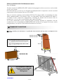
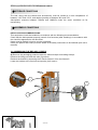
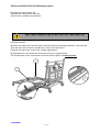
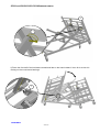
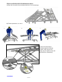
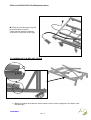
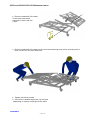
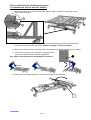
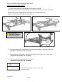
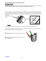
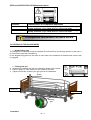
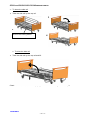
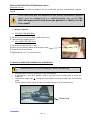
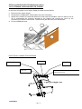
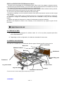
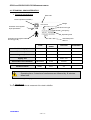
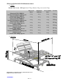
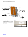
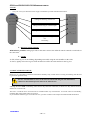
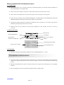
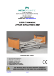
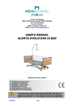
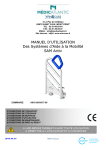
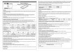
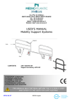
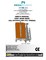
1 2 Le Pas du Château 85670 SAINT PAUL MONT PENIT FRANCE TEL.: 02-51-98-55-64 FAX: 02-51-98-59-07 EMAIL: [email protected] Website: http://www.medicatlantic.fr USER’S MANUAL VERY WIDE BEDS XXL DIVISYS AND XXL XPRESS CONTENTS IXX1L11/08-120/140 IXL2L11/08-120/140 TRANSPORT CONDITIONS STORAGE CONDITIONS ASSEMBLY CONDITIONS CONDITIONS FOR USE MAINTENANCE CONDITIONS CONDITIONS FOR SCRAPPING 17/06/2011 580040 IXX1L and IXL2L11/08-120/140 MEDICATLANTIC 17/06/2011 - 2 / 33 - IXX1L and IXL2L11/08-120/140 MEDICATLANTIC TABLE OF CONTENTS 1. Transport conditions……………………………………………………………………3 2. Transport conditions……………………………………………………………………4 3. Assembly conditions……………………………………………………………………4 3.1. Assembling the bed XXL X Press……..……………………………………………4 3.2. Purpose of bed………………………………………………………………………….9 3.3. Dismantling the beds XXL X Press and XXL….……………………………………11 3.4. Setup for use………………….……………………………………………………….13 3.5. List of accessories and compatible boards…...............…………...………………14 3.6. Setting up the accessories…….……………………………………………………..15 3.7. Instruction for dismantling the motors………………………………………………17 3.8. Flattening the back rest on the bed……….………………………………………..18 4. Conditions for use………………………….……………………………………………19 4.1. Purpose of bed……………………………..………………………………………...19 4.2. General description…………………………………………………………………..19 4.3. Technical characteristics…………………………………………………………….20 4.4. Use………………………………………………………………………………….….23 4.5. Precautions for use…………………………………………………………………..23 5. Maintenance conditions……………………………………………………..…………26 5.1. Maintenance………………………………….………………………………………27 5.2. Cleaning and disinfection……………………………………………..…………….30 5.3. Warrantee…………………………….………………………………………………31 5.4. Identification………………………………………………………………………….31 5.5. Lifetime…………………………………………………………….…………………31 6. Conditions for scrapping…………………………………………………………..…31 17/06/2011 - 3 / 33 - IXX1L and IXL2L11/08-120/140 MEDICATLANTIC Dear Sir/Madam, You have acquired a MEDICATLANTIC medical bed equipped with its accessories, and we thank you for your custom. Our beds and their accessories are designed and manufactured in compliance with the essential requirements of the European Directive 93/42/EEC. They are tested in conformity with standard NF EN 1970 (August 2000), its amendment A1 (July 2005), standard 60601-2-38 (October 1996; A1 of December 1999) and standard CEI 60601-252 (2009) in their commercial configurations, including the boards and accessories that we manufacture, so as to ensure you maximum safety and performance. As a result, maintenance of the contracted good’s warranty depends on compliance with the conditions for use recommended by MEDICATLANTIC and the use of original accessories, which also guarantees you safe use of the medical bed and its accessories. TRANSPORT CONDITIONS NB: When handling the bed base, it is preferable that the back and leg rests be strapped to the bed frame. 122cm for the 120 142cm for the 140 Cardboard 170 kg package with 120-11 bed, boards, side rails and lifting pole. 177 kg package with 140-11 bed. 213cm Pallet 70cm 76cm 136cm for the 120 156cm for the 140 205cm It is essential to raise the “support” prop ensemble to transport the XXL Divisys bed 17/06/2011 - 4 / 33 - IXX1L and IXL2L11/08-120/140 MEDICATLANTIC STORAGE CONDITIONS The bed, along with the boards and accessories, must be stored at a room temperature of between -10°C and +50°C, and relative humidity of between 30% and 75%. Atmospheric pressure between 700hPa and 1060hPa under the same conditions as for transporting. ASSEMBLY CONDITIONS INSTALLATION RECOMMENDATIONS: This equipment should be installed in accordance with the following recommendations: Check that the bed operates properly (test all of its functions) after installing it in accordance with the check-list appended to the document. Users must be trained in how to use the equipment. Users (the patient and carers) must be aware of the safety instructions to be followed (see user’s manual). 3.1 ASSEMBLING THE BED XXL X PRESS A) Remove the packaging protective devices, adhesive tape and holding clamps. Remove the lifting pole and side rails (if present). Remove the boards by loosening the 2 Rondo screws from the frames. Lower the holders to the first hole and put the pin back in. 1 3 2 17/06/2011 - 5 / 33 - IXX1L and IXL2L11/08-120/140 MEDICATLANTIC B) Remove the two fastening clips from the foot-half of the bed base. Remove the foot-half of the bed base and place it on the floor. C) Take the jack fastening clip out 1cm. Tilt the base-half and reinsert the clip. Remove the head-half of the bed base and place it on the floor. 1 D) Tilt the whole towards the floor and remove the fastening clip. 2 17/06/2011 - 6 / 33 - IXX1L and IXL2L11/08-120/140 MEDICATLANTIC E) Unfold the whole frame and separate the cross brace from the base until all 6 wheels are placed flat. THE 6 BED WHEELS MUST BE FLAT ON THE GROUND F) Brake the base. G) Place the head-half of the bed base centred and laid on the black brackets, and manually open the back rest so that the handle lies on the end of the base. Plug into the mains and connect the variable height jack. H) Assemble the cross brace with the remote-control in high position. Tilt the bed base on the cross brace and lock with the pins, handle upwards. 6 5 4 3 17/06/2011 - 7 / 33 - IXX1L and IXL2L11/08-120/140 MEDICATLANTIC 6 7 I) Place the foot-half of the bed base centred and laid on the base holders then tilt it so that it is resting on the cross brace bearings. 1 17/06/2011 - 8 / 33 - IXX1L and IXL2L11/08-120/140 MEDICATLANTIC J) Ease the foot-half of the bed base and lock it on the bearings. K) Follow operations a, b and c. b a c L) Once the base half is inserted, tighten the Rondo screws fully and put the safety clip in place to stop the bed base from separating. 1 2 17/06/2011 - 9 / 33 - IXX1L and IXL2L11/08-120/140 MEDICATLANTIC M) Finish by connecting the leg rest jack (according to option). Check that the wires are passed as shown in the photo on the right. 3.2 ASSEMBLING THE BED XXL DIVISYS 2 1 1) Brake the wheels and raise the cross braces until the mark is aligned on the base and the bearing. 17/06/2011 - 10 / 33 - IXX1L and IXL2L11/08-120/140 MEDICATLANTIC 2) Place the head-half of the base on the base/cross brace ensemble to lock it with the 2 clips. 3) Place the head-half of the base on the cross brace bearings and, with a second person’s help, connect it in the other base-half. 4) Tighten the Rondo screws. 5) Connect the variable height jack, leg rest jack (depending on option) and plug into the mains. 17/06/2011 - 11 / 33 - IXX1L and IXL2L11/08-120/140 MEDICATLANTIC 3.3 DISMANTLING THE XXL AND XXL XPRESS 6) Brake the wheels and lower the bed base until the mark is aligned on the base and cross brace bearing. 2 1 7) Remove the safety clip preventing the base from separating and loosen the two Rondo screws connecting the two half-bases. (Photos of stage L of the assembly.) 8) Remove the foot-half of the bed base and connect the leg rest jack (depending on option). 9) Lower the cross brace to low position, unplug from the mains, and disconnect the variable height jack. (See stage 3.6 Instructions for dismantling the motors) 10) Remove the two fastening clips to tilt the head-half of the bed base. 1 17/06/2011 - 12 / 33 - IXX1L and IXL2L11/08-120/140 MEDICATLANTIC Fold the base of the XXL X PRESS 11) Lift the cross brace as far as possible from the base (photo A). While keeping hold of the cross brace, fold the head-half of the base as shown in photo B. Put the cross brace fastening clip in place with the head-half of the base. Brake the 2 bottom wheels horizontally (photo C). A B Moderate effort required to stand the 27 kg base upright C 1 2 8) Stand the whole base up and put the head-half base in place by securing it with a clip. (See photo of stage C of the assembly) 9) Put the foot-half of the base in place by securing it with two clips (one on each side). (See photo of stage B of the assembly) 10) Finish by attaching the boards and lifting pole (See photo of stage A of the assembly) Dismountable weight 53 kg The base/cross brace ensemble of the bed exceeds 50 Kg. 17/06/2011 - 13 / 33 - IXX1L and IXL2L11/08-120/140 MEDICATLANTIC 3.4 SETUP FOR USE Put the bed in the designated room, foreseeing an appropriate perimeter of use for the different functions (variable height), especially if the bed has a lifting pole or side rails. Brake the castors and plug in the power lead, checking that the mains comply with the standards in force and that it is suitable for the supply box voltage. Also ensure that the power lead is positioned correctly to prevent any risks of getting caught between the moving parts of the bed. See below. Clip to secure the power lead Braking The brake on the 4 castors must be locked when the bed does not need to be moved. Check that the wheels are locked by trying to move the bed. If this is not done, the patient or another person who leans on the bed may fall. A A. Braking: press down on the brake with your foot. B. Releasing the brake: press down with your foot on the release lever. 17/06/2011 - 14 / 33 - B IXX1L and IXL2L11/08-120/140 MEDICATLANTIC 3.5 LIST OF ACCESSORIES Item Reference Bariatric Alova mattress XXL 120cm bed 84120120 Bariatric Alova mattress XXL 140cm bed 84120140 Alova mattress XXL 120cm bed 84100003 Alova mattress XXL 140cm bed 84100004 Epoxy lifting pole A 9300 Chrome-plated lifting pole A 1600 Stainless steel IV stand, 2 hooks A 17 00 Stainless steel IV stand, 4 hooks A 170001 Chrome-plated urine bottle holder A 5800 Stainless steel telescopic IV stand A 84 00 Chrome-plated wall-mounted basin holder A 193-00 Bed base extension 120 A 196-00 Bed base extension 140 A 521-00 Remote-control lead holder with magnet (linak) A 230-00 Epoxy folding side rails A 567-00 / A 568-00 Chrome-plated folding side rails A 571-00 / A 572-00 Epoxy urinal holder A 260-00 Full-length wooden barriers (with boards) A 314-00 / A315-00 Support handle A 575-00 Stainless steel serum holder on base with castors, 5 S0200 branches Lifting pole on U base Y0200 Bed skirt on wheels 120/140 on XXL only A 553-00 On fixed feet with skirt on XXL only Option a Infrared remote control Option b Max. load 270 Kg 270 Kg 135 Kg 135 Kg 75 Kg 75 Kg 8 Kg 8 Kg NA 8 Kg NA NA NA NA NA NA NA NA NA 8 Kg 75 Kg NA 270 Kg NA Only accessories and boards supplied by MEDICATLANTIC guarantee safe use. Compatible boards Reference Abélia 120 cm Abélia 140 cm Médiform 120 cm Médiform 140 cm Auzence 120 cm Auzence 140 cm Epoxy hand rails 120 cm Carmen 120 cm (with wooden barriers) Carmen 140 cm (with wooden barriers) Médiform 120 cm (with wooden barriers) Médiform 140 cm (with wooden barriers) Médidom 120cm Médidom 140cm Louis Philippe 120cm Louis Philippe 140cm P126-00 P146-00 P61 00 P63 00 P302-00 P303-00 P127-00 P226-00 P246-00 P262-00 P264-00 P297-00 P298-00 P116-00 P117-00 Assemble the highest board on the head side. 17/06/2011 - 15 / 33 - IXX1L and IXL2L11/08-120/140 MEDICATLANTIC Products Characteristics of compatible mattresses 120 cm wide bed Width 116 cm minimum with a high-resilience foam of 34 kg/m³ density minimum, height 14cm mini and 15 to 17cm maxi Width 136 cm minimum with a high-resilience foam of 34 kg/m³ density minimum, height 14cm mini and 15 to 17cm maxi 140 cm wide bed Incompatible mattresses can pose RISKS. 3.6 SETTING UP THE ACCESSORIES Angled lifting pole The lifting pole is intended to help the patient lift him/herself up and change position in the bed. It is not meant to help with transferring. Fit the angled lifting pole into the slots on each side of the head-end of the bed base until the tab is engaged. Folding side rail 1. Assemble the folding side rail in the direction shown by the photo 2. Leave a space of 4 cm maximum at the head of the bed. 3. Tighten the Rondo screws of the grip jaws on the bed base. 4 cm HEAD end FOOT end Indexing pin 17/06/2011 - 16 / 33 - IXX1L and IXL2L11/08-120/140 MEDICATLANTIC ⇒ To lower the side rail. 1. Take the side rail by the top rail. 3 2 Pull on the locking button. 4 ⇒ To raise the side rail. 1. Take the side rail by the top rail and lift. Check that the side rail is locked by trying to lower it without using the release pin. 17/06/2011 - 17 / 33 - IXX1L and IXL2L11/08-120/140 MEDICATLANTIC Precaution for use. There must be at least 220 mm between the top of the side rail and uncompressed mattress surface. If the side rails are not adapted or are poorly positioned, patient safety may be endangered or a malfunctioning may occur. The side rails must not be used when the patient is a child or if s/he is too small. Wooden side rail ⇒ TO RAISE THE SIDE RAIL. Raise the top side rail with both hands until it locks. Check that it is properly slot in. ⇒ TO LOWER THE SIDE RAIL. Raise the top side rail with 1 hand. Press on the unlocking button with the other hand. Support the rail as it lowers. Repeat steps to for the other side. 3.7 INSTRUCTIONS FOR DISMANTLING THE MOTORS Disconnect the 230 volts connection before dismantling. • • • • Dismantle when the bed is empty or in the side position If dismantling in any other position, keep a firm hold of the moving parts to avoid any shearing. Unblock the safety clips , unplug the motor leads, and remove them from the securing seals. Put the motors back in place and put in the same direction as at the beginning. Safety clip 17/06/2011 - 18 / 33 - IXX1L and IXL2L11/08-120/140 MEDICATLANTIC 3.8 FLATTENING THE BACK REST ON THE BED In the event of a power cut or failure, flatten the back rest as follows: a) Disconnect the power supply. b) Dismantle the headboard and wooden side rail if necessary. c) Stand at the head of the bed and take hold of the back rest handle with one hand. Push or lift to compensate the pressure exerted by the patient and unhook the clip by the connecting rod with the other hand. The back rest jack will then pivot downwards. d) Put the headboard back. 2 3 5 1 4 ELECTRICAL CONNECTION DIAGRAM Folding Variable height Plug Back rest Remote control, connection box or infrared receiver 1 2 3 4 HB Light grey supply box 17/06/2011 - 19 / 33 - IXX1L and IXL2L11/08-120/140 MEDICATLANTIC - The bed must be plugged into a dedicated socket. When use of an adaptor, extension lead or connection plug proves necessary, you must check that its characteristics are suitable for the bed. - The cleaning instructions recommended must be complied with. - The mains plug must be disconnected before the bed is moved. When the bed is being moved, the lead must not trail on the ground or get caught in the castors. -‐Do not pull on the mains leads to disconnect the mains plug. -‐ During any handling, try not to catch the leads of the motors and remote control and do not get them knotted. -‐ The condition of the leads must be checked frequently. If the slightest modification is observed, the person in charge for maintaining the bed must be contacted to carry out the necessary repairs. -‐ If repairs are required, the person in charge of maintenance must be contacted. Moreover, the telephone number of the company to be contacted for any repairs is given in this document. CONDITIONS FOR USE 4.1 PURPOSE OF BED The beds are not designed for children under 12, or for any other purpose apart from those stipulated below. Depending on their configuration, the beds are intended for home care. 4.2 GENERAL DESCRIPTION This bed has a headboard and footboard. See the types of board on offer in the price list. Back rest Back rest handle Mattress holders Bed base Headboard Angled lifting pole slots Footboard IV stand slots Leg rest handle Leg rest folding Castors Base and cross braces. Manual crank or electric folding leg rest depending on version. 17/06/2011 - 20 / 33 - IXX1L and IXL2L11/08-120/140 MEDICATLANTIC 4.3 TECHNICAL CHARACTERISTICS Electrical characteristics Bed code Class II (double insulation) Voltage XXXXXXX Protection level against liquid penetration Current type 66 Frequency Operating time Protection level against electric shocks (type B) Electrical data Absorbed power 200 VA TYPE PROTECTION INDEX VOLTAGE Variable height jack LA 27 8,000N IP 66 24V DC Back rest jack LA 27 6,000N IP 66 24V DC Leg rest jack LA 27 6,000N IP 66 24V DC Supply box CB 6 OBL IP 66 230 V AC Unlockable wired handset HB72/HB74 IP 66 24V DC IP21 3V Infrared control HB20 FREQUENCY 50 HZ Operating time: 2 minutes of continuous use followed by 18 minutes down time. The type and gauge of mains fuse F=(1AT) Sound level The maximum sound level measured of the bed is 49 dBa. 17/06/2011 - 21 / 33 - IXX1L and IXL2L11/08-120/140 MEDICATLANTIC Weight Normal load in use: 315 kg (Patient 270 kg, Mattress 30kg, Accessories 15kg) 120cm bed XXL XPRESS Version with manual crank leg rest 120cm bed XXL XPRESS Version with folding leg rest 140cm bed XXL XPRESS Version with manual crank leg rest 140cm bed XXL XPRESS Version with folding leg rest 120cm bed XXL Version with manual crank leg rest 120cm bed XXL Version with folding leg rest 140cm bed XXL Version with manual crank leg rest 140cm bed XXL Version with folding leg rest Base/cross brace Head-end bed base Foot-end bed base TOTAL 55 kg 26 kg 29 kg 110 kg 55 kg 26 kg 35 kg 116 kg 55 kg 29 kg 31 kg 115 kg 55 kg 29 kg 39 kg 123 kg 46 kg 26 kg 29 kg 101 kg 46 kg 26 kg 35 kg 107 kg 46 kg 29 kg 31 kg 106 kg 46 kg 29 kg 39 kg 114 kg Dimensions Médicatlantic recommends using a patient lift with a foot height of no more than 13.5 cm. 17/06/2011 - 22 / 33 - IXX1L and IXL2L11/08-120/140 MEDICATLANTIC Equipotentiality socket Under the head-half of the bed base you will find an equipotentiality socket , identified by the label , enabling you to connect any electromedical devices. The leads of these devices must pass through the head end and not the sides. Label Equipotentiality 17/06/2011 - 23 / 33 - IXX1L and IXL2L11/08-120/140 MEDICATLANTIC 4.4 USE - Carry out a test cycle when the bed is empty to familiarise yourself with the bed functions. Lifting and lowering of back rest Lifting and lowering of variable height Lifting and lowering of electric folding Simultaneous lifting and lowering of back rest and folding Infrared control (Option) Médicatlantic prohibits setting up 2 beds in the same room as the infrared control controls several beds at the same time. Cranks To lift, lift the leg rest or the folding (depending on model) using the wire handles on the sides. To lower, lightly relieve the leg rest with one hand to release the catch and lower the leg rest. 4.5 PRECAUTIONS FOR USE Before use, it is essential to read these instructions carefully. They contain advice on using and looking after the bed to guarantee optimum safety. The user and staff must be aware of the risks associated with using the bed and children, confused or disorientated persons must not be allowed on it. Although the bed is EMC conforming, some devices may alter how it functions, in which case they must be used at a distance or not used at all. The bed is a medical device and must not be modified under any circumstances. You must ensure its traceability, including that of the boards and its accessories. If you assemble different types of medical devices, you must conduct a risk analysis and make the CE declaration. 17/06/2011 - 24 / 33 - IXX1L and IXL2L11/08-120/140 MEDICATLANTIC The electric parts (jack, supply box, wired handset, etc) shall only be repaired by the manufacturer Linak. The bed is not suitable for use with an inflammable anaesthetic mixture with air or oxygen or nitrous oxide. The loads permitted (see bed characteristics) must be distributed evenly over the bed base. Do not sit down on the side of the back rest or leg rest if this is not flat. When a patient is in the bed, do not simultaneously activate the variable height motor or motors of the sleeping surface. After each movement of the bed and when the patient is being treated, it is essential to activate the 4 brakes to immobilise the bed. During rest, put the bed and all of the sections of the sleeping surface in low position to protect the patient from hurting him/herself. For greater safety, the side rails can be adapted (see accessories). The bed should not be used as a stretcher. When the bed is placed in low position, make sure that there are no objects and no parts of the patient’s or carer’s body caught between the boards, the accessories and the ground, between the boards and base or between the cross braces. When the bed is being moved, keep the power lead well away from the ground and castors. Powering up Connection to the supply box must be done using a mains complying with the standards in force and corresponding to a voltage of use of 230 V. The wired handset must be hooked to the headboard when not in use. During handling, the spiral lead and/or power lead should be kept away from moving parts such as the cross brace or back rest and should not be knotted. Only use original parts and accessories supplied by MEDICATLANTIC to guarantee safety and maintain product conformity. Abnormal use of the bed may damage it or cause accidents to users, in which case the warranty shall be annulled. Abnormal use means failure to comply with the precautions for use, maintenance instructions and other uses not related to the bed’s normal purpose, such as: use outdoors, moving the bed on a slope that is steeper than 10°, etc. Essential performances The bed will not move automatically when subject to electromagnetic disturbances within the limit of the values indicated below. In all situations, the bed allows the patient to have a horizontal sleeping surface. 17/06/2011 - 25 / 33 - IXX1L and IXL2L11/08-120/140 MEDICATLANTIC Manufacturer’s declaration and guide –electromagnetic emissions The medical bed (see references in contents) has been designed for use in the electromagnetic environment specified below. The user should ensure that it is used in such an environment Compliance Emissions test RF emissions Electromagnetic environment - Guide Group 1 The medical bed (see references in contents) uses RF energy only for its internal functions. Therefore, its RF emissions are very low and are not likely to cause any interference in nearby electronic equipment. Class B The medical bed (see references in contents) can be used in all domestic environments, including those directly connected to the public low-voltage power supply network that supplies buildings for domestic purpose. Class A [] CISPR 11 RF emissions CISPR 11 Harmonic emissions EN 61000-3-2 Applicable Voltage fluctuations / Flicker EN 61000-3-3 Compliant RF emissions The medical bed (see references in contents) has not been designed for connection to other equipment. CISPR 14-1 Manufacturer’s declaration and guide –electromagnetic immunity The medical bed (see references in contents) has been designed for use in the electromagnetic environment specified below. The user should ensure that it is used in such an environment CEI 60601 Immunity test Compliance level Electromagnetic environment - Guide L Severity level Electrostatic discharge ± 6 kV contact EN 61000-4-2 ± 8 kV air ± 6 kV contact ± 8 kV air Floors should be wood, concrete, or ceramic tile. If floors are covered with synthetic material, the relative humidity should be at least 30 %. Electrical fast transients ± 2 kV for feeders ± 2 kV for feeders The quality of the main power supply must be the same as for a typical commercial or hospital environment. ± 1 kV for input/output lines ± 1 kV for input/output lines Differential mode ± 1 kV Differential model ± 1 kV Common mode ± 2 kV / EN 61000-4-4 Surges EN 61000-4-5 Voltage dips, short interruptions and voltage variations • <5% UT - for 10 ms • <5% UT – for 10 ms • 40% UT - for 100 ms • 40% UT - for 100 ms EN 61000-4-11 • 70% UT - for 500 ms • 70% UT - for 500 ms • <5% UT - for 5 s • <5% UT - for 5 s 3 A/m Power frequency magnetic field (50/60 Hz) The quality of the main power supply must be the same as for a typical commercial or hospital environment. The quality of the main power supply must be the same as for a typical commercial or hospital environment. If the user of the medical bed (see references in contents) wants to be able to continue to use the bed during interruptions in the main power supply, it is recommended that the bed be powered by a converter or battery. 3 A/m Power frequency magnetic fields should be at levels characteristic of a typical location in a typical commercial or hospital environment. NB: UT is the nominal value of power voltage applied during the test. Manufacturer’s declaration and guide –electromagnetic immunity The medical bed (see references in contents) has been designed for use in the electromagnetic environment specified below. The user should ensure that it is used in such an environment CEI 60601 Immunity test Compliance level Electromagnetic environment - Guide Severity level Portable and mobile RF communications equipment should be used no closer to the medical bed (see references in contents), including leads, than the recommended separation distance, calculated using equations applicable to the frequency of the transmitter. Recommended separation distance Conducted RF 3 Vrms EN 61000-4-6 150 kHz to 80 MHz Radiated RF 3 V/m EN 61000-4-3 80 MHz to 2.5 GHz 3V d = 1,17 P 3 V/m 80 to 800 MHz d = 1,17 P 80 MHz to 800 MHz d = 2,33 P 800 MHz to 2.5 GHz 2 to 2.5 GHz 10 V/m 800 MHz to 2 GHz P where is the maximum output power rating of the transmitter in watts (W) according to the transmitter manufacturer and d the recommended separation distance in metres (m). The field strengths transmitted by fixed RF transmitters, determined by an electromagnetic a measurement of the site , must be less than the conformity level in each range of frequencies. Disturbances can occur near devices marked with this symbol: 17/06/2011 - 26 / 33 - IXX1L and IXL2L11/08-120/140 MEDICATLANTIC Note 1 At 80 MHz and 800 MHz, the upper frequency range applies. Note 2 These guidelines may not apply in all situations. Electromagnetic propagation is affected by absorption and reflection from structures, objects and people. A Field strengths from fixed transmitters, such as base stations for radio (cellular/cordless) telephones and land mobile radios, amateur radio, AM and FM radio broadcast and TV broadcast cannot be predicted theoretically with accuracy. To assess the electromagnetic environment due to fixed RF transmitters, an electromagnetic site survey should be considered. If the measured field strength in the location in which the medical bed (see references in contents) is used exceeds the applicable RF compliance level above, the AccuGuide® Monitor should be observed to verify normal operation. If abnormal performance is observed, additional measures may be necessary, such as re-orienting or relocating the medical bed. B Over the frequency range 150 kHz to 80 MHz, field strengths should be less than 3 V/m Recommended separation distances between portable and mobile RF communications equipment and the medical bed (see references in contents) The medical bed (see references in contents) is intended for use in the electromagnetic environment in which radiated RF disturbances are controlled. The customer or the user of the bed can help prevent electromagnetic interference by maintaining a minimum distance between portable and mobile RF communications equipment (transmitters) and the bed as recommended below, according to the maximum output power of the communications equipment. Separation distance according to frequency of transmitter m Rated maximum power of transmitter 150 kHz to 80 MHz 80 MHz to 800 MHz 800 MHz to 2.5 GHz d = 1,17 P d = 1,17 P d = 2,33 P 0.01 0.12 / 0.116 0.12 / 0.116 0.23 / 0.233 0.1 0.37 / 0.316 0.37 / 0.366 0.74 / 0.736 1 1.17 / 1.16 1.17 / 1.16 2.33 / 2.33 10 3.70 / 3.66 3.70 / 3.66 7.37 / 7.36 100 11.70 / 11.6 11.70 / 11.6 23.30 / 23.3 W For transmitters rated at a maximum output power not listed above, the recommended separation distance d in meters (m) can be estimated using the equation applicable to the frequency of the transmitter, where P is the maximum output power rating of the transmitter in watts (W) according to the transmitter manufacturer. Note 1 At 80 MHz and 800 MHz, the separation distance for the higher frequency range applies. Note 2 These guidelines may not apply in all situations. Electromagnetic propagation is affected by absorption and reflection from structures, objects and people. MAINTENANCE CONDITIONS The quality of the medical beds will be inspected: -by trained technical or biomedical staff; -by taking account of the normal conditions for use specified in the user’s manual on a bed equipped with specific safety rails. The bed must be available for carrying out a full quality inspection at least once a year, but also: -on specific request -after curative maintenance on performances which could have been affected by the repairs. However, to save time, this may be carried out at the same time as preventive maintenance. In this case, it is not worth carrying out a new inspection of performances that have already been checked. With external test devices to the medical bed, compatible with the performances claimed; -by referring to the user’s manual if necessary. 17/06/2011 - 27 / 33 - IXX1L and IXL2L11/08-120/140 MEDICATLANTIC 5.1 MAINTENANCE RECOMMENDATIONS FOR PREVENTIVE MAINTENANCE: Preventive maintenance should be carried out in accordance with our specifications and at least once a year by the organisation or person who installed the bed. Between two maintenance sessions and at least once a year, the following should be carried out: - Verification that the electrical leads are connected all along the metal jambs to prevent shearing of these leads when the variable height is being activated. - Verification that all of the electrical leads and plugs are in good condition. Replacement if there is the slightest alteration (wear, shearing, damage, etc.). - Verification of the external appearance (traces of damp and good overall condition of protective covers in particular) and that the motors and jacks function properly. - Verification that the bed is in good working order (test all functions). - Verification that the frame, bed base and mechanical joints are all in good condition. When maintenance is carried out at the patient’s home as part of a long-term contract, the installer must also: - Check the bed is properly installed (check to see that there hasn’t been any modification contrary to the safety instructions made by the user since the bed’s installation). - Remind the users of the safety instructions. -All installation and preventive maintenance operations must be recorded. See table model below. This record must be kept in a designated area throughout the bed’s lifetime. QUALITY INSPECTION OF MEDICAL BEDS IDENTIFICATION OF MEDICAL BED ESTABLISHMENT CATEGORY TYPE MODEL TRADEMARK SERIAL NO. SERVICE SITE INVENTORY NO. DATE OF MANUFACTURE TEST DEVICES CHECKED AND CONFORMING WITH STANDARDS Description Type/model Identification/serial no. Mass continuity tester Dielectrimeter Fault current to patient Qualitative aspects VISUAL CHECKS General condition User’s manual available Headboard and footboard present Good overall condition (head and foodboards, bed corners, protective stops) General cleanliness Acceptable state of corrosion given the requirements of the user Identification/label/serigraphy in good condition Mechanical condition Lifting pole in good condition (positioning and strap) Mechanical leads in good condition Sleeping surface in good condition (bed base) Boards lock and tighten well (head and footboards) Chest rest functions properly Leg rest functions properly Half-seated position functions properly 17/06/2011 - 28 / 33 - NA (1) YES NO IXX1L and IXL2L11/08-120/140 MEDICATLANTIC Manual leg rest functions properly TR/RTR positions function properly Bed base extension functions properly Castors function properly (pivoting, rolling, etc.) including the steering castor where applicable. Bed immobilises properly (castor brakes, etc.) Verification of tightenings, diverse nuts and bolts, pins, pivot, IV stand Qualitative aspects NA (1) YES NO NA (1) YES NO NA (1) YES NO NA (1) YES NO Verification that welds are in good condition Absence of sound disturbances (squeaking, lubrications) Electrics, hydraulics and pneumatics Electrical leads, plugs and connectors are in good condition (not sheared, not caught, etc.) Electrical parts in good condition (leads, motors, boxes, etc.) Hydraulic and pneumatic parts in good condition (pumps, compressors, jacks, dampers, etc.) Remote controls, displays and lights in good condition Bed-specific side rails The rails in place and specific to the bed and/or comply with the manufacturer’s specifications Properly positioned and secured Side rail locking functions properly in raised position Check that the height measured from the top of the barrier to the uncompressed mattress surface, excluding therapeutic mattresses, is more than or equal to 220 mm (complies with the standard in force) 2 Safety check Locking of operational functions Inactivation of variable height control pedals Cardio Pulmonary Resuscitation (CPR) emergency flattening of the back rest Check that the headboard extracts or retracts properly in an emergency Check that the chest rest emergency flattening function works properly Withstands jack load well Visual and sound alarms in good working order Quantitative aspects Bed functions properly using the battery Check the scale of movements Maximum angle when propped = Maximum angle of specifications claimed by the manufacturer (± 2°) Maximum height = Maximum height of specifications claimed by the manufacturer (± 20 mm) Minimum height =Minimum height of specifications claimed by the manufacturer (± 17/06/2011 - 29 / 33 - IXX1L and IXL2L11/08-120/140 MEDICATLANTIC 20 mm) Electrical safety Electrical safety inspection (Values comply with EN 60601-1) Comments Conclusion YES NO Operational (is the safety of the patient, carers and technical staff at risk?) Plan of action (see comments) 3 Recommended date of next quality inspection OPERATOR NAME Establishment DATE Signature 1 Not Applicable 2 If the height measured does not comply with the standard, the health manager responsible for correct application must be informed. Failure to comply is not a criterion for a non operational status. 3 The manager decides on the actions to take and which people to contact depending on the results of the quality inspection and the comments made. 17/06/2011 - 30 / 33 - IXX1L and IXL2L11/08-120/140 MEDICATLANTIC 5.2 CLEANING AND DISINFECTION High-pressure cleaning is forbidden. Unplug the mains lead. Check that all the electrical parts are connected together. All the sockets of the supply box must be used, otherwise the watertightness of it is not guaranteed. Clean the electric covers of the jacks and wired handset straightaway if any bodily fluids, particularly urine, have sprayed on to them. Isolate the medical bed in a disinfection room equipped with a particle filtering system and drain for washing floors and walls after disinfection. How to use the WIP’ANIOS cloth Carefully wipe the surface to be treated and use a second cloth if the surface is very dirty. The surface only needs rinsing in the event of: subsequent contact with mucous membranes, possible contact with unwrapped foodstuffs. Qualitative compositions The impregnation solution of the WIP’ANIOS cloths contains: .Didecyldimethylammonium chloride, .Isopropanol,(8%p/p), .Fatty alcohol ethoxylate type detergent. Physicochemical properties Impregnation solutions of cloths 5ml per cloth. Size 200 mm x 200 mm Microbiological properties The impregnation solutions of the cloths have a microbial effectiveness -Bactericide NF EN 1040 -Bactericide in the presence of interfering substances NF EN 1276 pr EN 13713. -Bactericide in carrier method: NF T 72190 (spectrum 4). -Active on Mycobacterium tuberculosis (BK). -Active on Candida albicans: NF EN 1275. -Fungicide in the presence of proteins: NF EN 1650 -Active on herpes virus and Rota virus Leave to dry and protect the equipment from being contaminated by other non-disinfected equipment with a film labelled with the date of disinfection. Product for external use. Do not swallow, keep away from heat sources and avoid contact with eyes 17/06/2011 - 31 / 33 - IXX1L and IXL2L11/08-120/140 MEDICATLANTIC 5. 3 WARRANTIES All of our products carry a warranty against any manufacturing defect, provided the normal conditions for use and maintenance are complied with. Labour costs due to changes in structures or parts under warranty are not taken into account. Please refer to the standard terms of sale for the specific terms of warranty for each product. Every time you contact us for possible maintenance, you must quote us the information on the bed identification label and on the electric parts if these are concerned. Original parts shall be supplied for replacement, within the term of warranty, by our customer sales network determining the beginning of the term of warranty. Defective parts must be returned to ensure proper application of this warranty and also to avoid any invoicing. 5. 4 IDENTIFICATION Manufacturer Product identification CE marking Refer to user’s manual Serial number and date of manufacture Address Refer to user’s manual 270 Kg Maximum patient weight 315 Kg Safe operational load 5.5 LIFETIME The bed’s lifetime under normal conditions of use and maintenance is: 5 years CONDITIONS FOR SCRAPPING The product must be scrapped if the main requirements are no longer met, particularly when the product no longer has its original characteristics and has not been subject to corrective action during the manufacturing process. Measures should therefore be taken to ensure that the bed is no longer used for the purpose it was originally intended. When scrapping, the current environmental standards must be complied with. 17/06/2011 - 32 / 33 - IXX1L and IXL2L11/08-120/140 MEDICATLANTIC Le Pas du Château 85670 SAINT PAUL MONT PENIT FRANCE TEL.: 02-51-98-55-64 FAX: 02-51-98-59-07 EMAIL: [email protected] Website: http//: www.medicatlantic.fr 17/06/2011 - 33 / 33 -