1
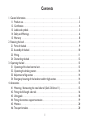
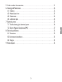
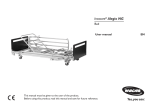
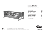
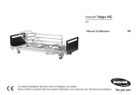
Invacare® Medley Ergo Bed - Bett - Cama - Lit - Letto User manualEN Gebrauchsanweisung DE GebruiksaanwijzingNL Manual de utilizaçãoPT Manuel d’utilisationFR Manual del usuario ES Manuale d’usoIT This manual must be given to the user of the product. Before using this product, read this manual and save for future reference. Invacare® Medley Ergo User manualEN3 GebrauchsanweisungDE3 GebruiksaanwijzingNL3 Manual de utilizaçãoPT3 Manuel d’utilisationFR3 Manual del usuarioES3 Manuale d’usoIT3 Contents 1. General information. . . . . . . . . . . . . . . . . . . . . . . . . . . . . . . . . . . . . . . . . . . . . . . . . . . . . . . . . . . . 3 1.1 Product use. . . . . . . . . . . . . . . . . . . . . . . . . . . . . . . . . . . . . . . . . . . . . . . . . . . . . . . . . . . . . . . 3 1.2 Certification. . . . . . . . . . . . . . . . . . . . . . . . . . . . . . . . . . . . . . . . . . . . . . . . . . . . . . . . . . . . . . 4 1.3 Labels and symbols. . . . . . . . . . . . . . . . . . . . . . . . . . . . . . . . . . . . . . . . . . . . . . . . . . . . . . . . . 5 1.4 Safety and Warnings. . . . . . . . . . . . . . . . . . . . . . . . . . . . . . . . . . . . . . . . . . . . . . . . . . . . . . . . 6 1.5 Warranty . . . . . . . . . . . . . . . . . . . . . . . . . . . . . . . . . . . . . . . . . . . . . . . . . . . . . . . . . . . . . . . . 8 2. Receiving the bed. . . . . . . . . . . . . . . . . . . . . . . . . . . . . . . . . . . . . . . . . . . . . . . . . . . . . . . . . . . . . . 9 2.1 Parts of the bed. . . . . . . . . . . . . . . . . . . . . . . . . . . . . . . . . . . . . . . . . . . . . . . . . . . . . . . . . . . 9 2.2 Assembly of the bed. . . . . . . . . . . . . . . . . . . . . . . . . . . . . . . . . . . . . . . . . . . . . . . . . . . . . . . 10 2.3 Wiring. . . . . . . . . . . . . . . . . . . . . . . . . . . . . . . . . . . . . . . . . . . . . . . . . . . . . . . . . . . . . . . . . . 11 2.4 Dismantling the bed. . . . . . . . . . . . . . . . . . . . . . . . . . . . . . . . . . . . . . . . . . . . . . . . . . . . . . . 12 3. Operating the bed . . . . . . . . . . . . . . . . . . . . . . . . . . . . . . . . . . . . . . . . . . . . . . . . . . . . . . . . . . . . 13 3.1 Operating of the hand control unit.. . . . . . . . . . . . . . . . . . . . . . . . . . . . . . . . . . . . . . . . . . . 13 3.2 Operating the braking castors. . . . . . . . . . . . . . . . . . . . . . . . . . . . . . . . . . . . . . . . . . . . . . . 14 3.3 Adjustment of leg section . . . . . . . . . . . . . . . . . . . . . . . . . . . . . . . . . . . . . . . . . . . . . . . . . . 14 3.4 Emergency lowering of the backrest and/or thigh section. . . . . . . . . . . . . . . . . . . . . . . . . 14 4. Accessories. . . . . . . . . . . . . . . . . . . . . . . . . . . . . . . . . . . . . . . . . . . . . . . . . . . . . . . . . . . . . . . . . . 15 4.1 Mounting / dismounting the steel side rail (Scala 2 & Verso 11). . . . . . . . . . . . . . . . . . . . . 15 4.2 Fitting the full length side rails. . . . . . . . . . . . . . . . . . . . . . . . . . . . . . . . . . . . . . . . . . . . . . . 16 4.3 Lifting pole . . . . . . . . . . . . . . . . . . . . . . . . . . . . . . . . . . . . . . . . . . . . . . . . . . . . . . . . . . . . . . 18 4.4 Fitting the mattress support extension. . . . . . . . . . . . . . . . . . . . . . . . . . . . . . . . . . . . . . . . 19 4.5 Mattress . . . . . . . . . . . . . . . . . . . . . . . . . . . . . . . . . . . . . . . . . . . . . . . . . . . . . . . . . . . . . . . . 20 4.6 Transport brackets. . . . . . . . . . . . . . . . . . . . . . . . . . . . . . . . . . . . . . . . . . . . . . . . . . . . . . . . 20 1 2 21 22 22 23 24 24 25 26 27 32 32 33 35 35 EN 5. Order numbers for accessories. . . . . . . . . . . . . . . . . . . . . . . . . . . . . . . . . . . . . . . . . . . . . . . . . . 6. Cleaning and Maintenance. . . . . . . . . . . . . . . . . . . . . . . . . . . . . . . . . . . . . . . . . . . . . . . . . . . . . . 6.1 Cleaning . . . . . . . . . . . . . . . . . . . . . . . . . . . . . . . . . . . . . . . . . . . . . . . . . . . . . . . . . . . . . . . . 6.2 Maintenance chart . . . . . . . . . . . . . . . . . . . . . . . . . . . . . . . . . . . . . . . . . . . . . . . . . . . . . . . . 6.3 Maintenance. . . . . . . . . . . . . . . . . . . . . . . . . . . . . . . . . . . . . . . . . . . . . . . . . . . . . . . . . . . . . 6.4 Lubrication plan. . . . . . . . . . . . . . . . . . . . . . . . . . . . . . . . . . . . . . . . . . . . . . . . . . . . . . . . . . 7. Electrical system. . . . . . . . . . . . . . . . . . . . . . . . . . . . . . . . . . . . . . . . . . . . . . . . . . . . . . . . . . . . . . 7.1 Trouble-shooting the electrical system . . . . . . . . . . . . . . . . . . . . . . . . . . . . . . . . . . . . . . . . 7.2 Electro Magnetic Compliance (EMC) . . . . . . . . . . . . . . . . . . . . . . . . . . . . . . . . . . . . . . . . . 8. Technical specifications. . . . . . . . . . . . . . . . . . . . . . . . . . . . . . . . . . . . . . . . . . . . . . . . . . . . . . . . . 8.1 Dimensions. . . . . . . . . . . . . . . . . . . . . . . . . . . . . . . . . . . . . . . . . . . . . . . . . . . . . . . . . . . . . . 8.2 Environmental conditions. . . . . . . . . . . . . . . . . . . . . . . . . . . . . . . . . . . . . . . . . . . . . . . . . . . 8.3 Weights. . . . . . . . . . . . . . . . . . . . . . . . . . . . . . . . . . . . . . . . . . . . . . . . . . . . . . . . . . . . . . . . . 9. Waste disposal . . . . . . . . . . . . . . . . . . . . . . . . . . . . . . . . . . . . . . . . . . . . . . . . . . . . . . . . . . . . . . . Congratulations Congratulations on your choice of Invacare® Medley Ergo nursing bed. Medley Ergos is the dismantable nursing bed from Invacare® designed especially for home nursing. Medley Ergo bed provides ease of handling combined with good functionality. Please read the entire user manual before using the bed. If you have any questions concerning the use or maintenance, please contact us. All indications of right and left are based on that a person lying on his back in the bed. Please note that there may be sections in this user manual, which are not relevant to your bed, since this manual applies to all (on the date of printing) existing modules. 1. General information 1.1 Product use • • • • • • • • • The Medley Ergo bed has been developed for domestic care, long term care and features a comfortable sitting and lying position for the patient. Furthermore, ergonomical operation for the carer is ensured. The Medley Ergo bed is defined to be used according to; Application environment 3; Long-term care in a medical area where medical supervision is required and monitoring is provided if necessary and medical electrical equipment used in medical procedures may be provided to help maintain or improve the condition of the patient. Application environment 4; Care provided in a domestic area where medical electrical equipment is used to alleviate or compensate for an injury, disability or disease. = 145 kg If the patient height exceeds 2 meters it is recommended to use a mattress support extension. The max. patient weight: 145 kg, provided that the weight of the mattress and the accessories do not exceed 35 kg. (Safe working load weight: max. 180 kg). = 180 kg The bed is not intended for children under 12 years and psychiatric patients. Furthermore; Be aware of the limitations of use mentioned in the warnings. (chapter 1.4) The following parts may be in contact with user during normal use of bed: bed ends, mattress deck, mains cord and hand control. The Medley Ergo is not intended to be used for patient transport. The Medley Ergo bed is suitable for disinfection with household disinfectants. 3 • • • • The Medley Ergo is suitable for refurbishment. The estimated product life cycle is 5 years for a Medley Ergo bed. The bed is quipped with loose cables, which have to be exchanged if damaged. The control unit, external power supply, hand control and motors are protected according to IPX4. (The IP rating is a measure of protection against ingress of foreign matter into a product) Remove the plug from the mains voltage before moving the bed. The cable must be kept clear off the floor and the castors during transportation. The adjustment area of the mattress support is: 40-80 cm or alternatively 33-73 cm for Medley Ergo*. The adjustment area of the mattress support is: 28-68 cm or alternatively 21-61 cm for the Medley Ergo Low*. The angle between the lower leg section and horizontal is adjustable from 0º to 15º. EN • • • • 1.2 Certification • • • • • The Medley Ergo bed is marked with the CE - mark in accordance with directive 93/42/EEC concerning Medical Apparatus. Medley Ergo bed have been approved according to IEC 60601-2-52 (Beds provided with tilt function can not be approved according to IEC 60601-2-52) The Medley Ergo bed has been approved and marked with the TÜV mark. The Medley Ergo bed has undergone a risk analysis according to EN ISO 14971:2001-03 The Medley Ergo bed has undergone a usability analysis according to IEC 60601-1-6 Invacare® is certified according to DS/EN ISO 9001 and ISO 13485 which ensures that our customers are always supplied with products of uniform quality. Throughout the entire production process our materials/products are quality controlled by the operators. Additionally, a final test is carried out prior to packaging and shipping. If the product does not correspond to the quality demands of Invacare®, it will be discarded. If, contrary to our expectations, a problem should arise in connection with the delivered product, please contact your Invacare® supplier. An address list is shown on the back side at this manual. Invacare® reserves the right to alter product specifications without prior notice. 4 1.3 Labels and symbols WARNING - This symbol warns of dangers. If the necessary measurings not are taking, it can result in injury or damage to the bed. NOTE - This symbol inform about important information and guidelines. Instruction - Reference to the user manual. To identify the product please look at the Product-label (located on headrest cross brace). Electrical information See chapter 7 Type no. of the bed. Serial no. Date of production. Symbols See chapter 1 and 7 5 1.4 Safety and Warnings The Medley Ergo bed fulfils all requirements regarding maximum distances. However, if the bed is used for the care of patients with a small body dimensions, it must be especially noted that there is a risk of such a patient slipping through the openings between the side rails or through the opening between the side rail and the mattress support. The bed must not be used by patients under 12 years of age, or by patients with body size equivalent to an average 12 years old or smaller. The bed, in combination with side rails must not be used for persons under 45 kg or under 150 cm height. Either for persons that are restless (spasms) or confused, unless a professional risk assessment has taken place and been accepted. When using side rails it is essential to ensure correct fitting - otherwise there is danger of entrapment / suffocation between mattress support, side rail and bed end. Do not place any objects underneath bed. 6 EN Invacare® accepts no liability for any use, change or assembly of the product other than as stated in this user manual. Accessories not mentioned in this manual must not be used. Electromagnetic interference between the bed and other electrical products can occur. To reduce or eliminate such electromagnetic interference, increase the distance between the bed and the products or switch them off. This medical bed can be used together with medical electrical equipment connected to the heart (intracardially) or the blood vessels (intravascularly), provided that following points are respected: • The medical bed should be equipped with means for potential equalization connection marked out by a symbol shown in the back of this manual. • Medical electrical equipment as describe above, should not be fixed on the bed’s metallic accessories such as side rails, lifting pole, drip rod, bed ends ect. In addition, the medical electrical equipment power supply cord should be kept clear of the accessories or any other moving part of the bed. Make sure that there are nothing under, over, or near the bed that can limit the movement of the bed or the mattress support, such as furniture, window frames and storage boxes. Always lower the bed to the lowest position before leaving the patient in the bed unattended. There is a risk of entrapment of fingers in the bed moving parts. Never lower deck height of bed more than 40 cm when using bed with a lifter. Use ground clearance info in section 8 of this manual to determine lifter compatibility with bed before use. • It can be dangerous to roll over the mains cable. • Do not bring mains cable into moving parts. • Disconnect the plug from the mains before moving the bed. • The cables must be mounted in such a way that they are kept clear of the floor and do not block the castors. We recommend to mount the mains cable on the hook for this purpose, see picture. 7 1.5 Warranty The warranty covers all material and production defects for 2 years from the date of delivery, provided it can be demonstrated that such defects were present before delivery. All manufacturing faults or defects must be promptly reported Invacare® may repair the fault or replace the component. The warranty provided by Invacare® does not cover additional costs (transport, packaging, labour, sundry expenses, etc. are for the customer’s account). Damage caused during transport that is not directly reported to the forwarder at the moment of delivery. Repairs performed by unauthorized centers and personnel. Parts subject to normal wear. Malicious damage or damaged caused by improper use of the bed. 8 EN The warranty does not cover: 2. Receiving the bed 2.1 Parts of the bed Check the packaging, if the bed shows any signs of damage upon delivery, please see the terms of delivery. Follow part must be provided: 1. 2. 3. 4. 5. 6. 7. 8. Pair of bed ends Mattress support, head end 4 pcs. of mattress support bracket Motor for head end. Mattress support, foot end Motors for bed end. Castors Hand control Optional : Transport fittingSupport handle Lifting poleSafety floor mattress Rastofix for leg section Wood cover for bed ends Mattress support extension (15 cm) Equipotentiality plug Motor for leg end Side rail (wood) Side rail (steel) Side rail (Verso 11) Side rail (Scala 2 series) Side rail height extender 9 2.2 Assembly of the bed For questions concerning the assembly of your bed please contact your dealer or Invacare customer service. Mattress Support 1. Push the foot end of the mattress support onto the head frame. 2. Tighten with two thumb screws. 3. Turn the four mattress handles of the backrest and footrest up. 4. Turn the locking ring* on the bed ends to the position “open” 5. Latch the mattress support to the bed ends and press firmly into position**. 6. Make sure that the bed ends are in the same level. It is possible to level the bed in high position (A) and low position (B). 7. Turn the locking ring to the position “lock”. Always put locking ring in the upper slot as shown in pictures * The locking rings locks ensure that the mattress support is not accidentally lifted clear of the bed ends. ** It is normal to have a small space between the top of the slot on the mattress hook and the bracket on the bed end. EN Space Bracket Hook Rastofix 1. 2. 1. & 2. Press bottom of Rastofix at the foot end of the bed 3. 4. 3. Squeeze upper end of Rastofix together 10 4. Rotate Rastofix between tabs and release Control Box The control box is latched to the backrest motor. The control box is provided with a label with symbols showing where to connect the motors’ plugs. • Backrest motor. • Bed end motors. • Thigh section’s motor. • Hand control. 2.3 Wiring In order to prevent the cables from being torn apart when activating the motors it is very important to follow the instructions below. 1. Connect the cables of the bed end motors (head and foot end) directly to the control box. 2. Wire the cable of the bed end motor (foot) through the pipe pin of the thigh motor. 3. The cable of the thigh motor must be directed through the pipe pin of the thigh motor. 4. Connect the mains cable to the 230 V plug. 5. Run the motors of the bed ends to their top position. 6. Place the motor cable of the foot end on the hook at the foot end. 7. Run the backrest to its top position. 8. Place the head end motor cables on the 2 hooks at the head end and through the pipe pin of the backrest motor. 9. Fasten the safety clip to the control box. 10. Verify that the mains cable strain relief is attached to bed frame. 11. For Medley Ergo with 24 V external power supply, verify that mains cable is attached to control unit power supply cable. Improper routing, kinking, shearing or other mechanical damages of cables could lead user injury. 1. 3. 6. 8. 10. 11. After completion of assembly, always check that bed is fully functional before placing patient in bed. 11 2.4 Dismantle the bed Dismantle siderails and lifting pole. Bring the bed to its lowest position and adjust all mattress support sections to horizontal position. Disconnect the power card. Roll the cable onto the hook of the head end of the bed. Disconnect all the motor plugs from the motors (do not disconnect the backrest motor cable - cable 1). Dismantle the safety comb from the control by means of a tool, e.g. a flat headed screwdriver. Pull out the cables of the bed end motors and leg section motor. Separate the mattress support from the bed ends. Divide the head and foot end of the mattress support. EN • • • • • • • • 12 3. Operating the bed UP/DOWN UP/DOWN 3.1 Operating of the hand control unit. Sitting position Thigh section (optional) Height adjustment of the bed Key for locking and unlocking the electrical functions. Insert the key below each button to respectively lock and unlock the hand control functions. HL 70 (with integrated ACP function) HB70 The beds can be equipped with a hand control that activate the tilt of the mattress support, this hand control can be ordered from Invacare® - please refer to the section ”Order numbers for accessories”. Medically trained persons must only operate the tilt function - otherwise, there is a risk of injury to the patient´s health. To deactivate bed functions, remove mains cord plug from power outlet. 13 3.2 Operating the braking castors Marks from the castors might under special conditions appear on different types of absorbing floor covering including untreated or badly treated floors. In matters of doubt, Invacare® recommends placing a suitable kind of protection between the castors and the floor. Do not release the brake with the fingers as there can be a risk of trapping. Always apply the brakes when there is no need for moving the bed, to avoid accidents during entering or exiting the bed, and during handling of the patient. 1 EN When the bed is positioned correctly, at least one castor at the head end and one castor in the foot end must be braked. Braking: Step on the pedal. (pos. 1) Releasing the brake: Push up on underside of brake pedal. Each of the castors is provided with brakes for both lengthwise and crosswise locking. The brake is foot-operated. Placement in the room The bed must be placed so that the height adjustment (up/down) is not obstructed by, for example, lifts or furniture. Otherwise there is a risk for injury on user and/or equipment. 3.3 Adjustment of leg section (optional) Operate the leg section by lifting the leg section. Up: Lift the leg section. Down: Lift the leg section right up and then lower the leg section. 3.4. Emergency lowering of the backrest and/or thigh section An emergency release of the mattress support may be necessary in case of e.g. a power- or motor failure. An emergency release of the height adjustment is NOT possible. 14 Remove the plug from the mains before emergency release of the mattress support. 1) Hold the backrest. 2) Remove the pipe pin from the backrest motor. 3) Lower the backrest motor. 4) Lower the backrest. A minimum of 2 persons are required to emergency release a mattress section. Both persons hold the mattress section. One person pulls out the pipe pin. Both slowly lower the mattress section until it is completely down. 4. Accessories When 3/4 length using side rails you must always make sure that the distance between the bed end and the side rail’s handle upper edge is between 3 - < 6 cm for the the head section and more than 32 cm for the foot section There is a risk of entrapment of fingers on assembly and operation of the side rail. 4.1 Mounting / dismounting the Scala 2 series and Verso 11 steel side rail Mounting The side rail must be mounted according to the assembly instruction side rail. Tighten the side rail with the finger screws. 1) 3 - < 6 cm Dismounting Loosen the finger screws and remove the side rail. 15 2) 32 cm A: Disassembled gliding system 4.2 Fitting the full length side rails The installation of steel- and wooden side rails are identical 1) The gliding system consists of 5 different parts which all must be installed simultaneously. A disassembled gliding system is shown in illustration A. Pawl Glider C:Installation B:Removal EN The 4 pawls are clipped onto the glider (B and C). CLICK! 2)For an ergonomic working position and easier assembly, raise the bed to 1/3 of full height position. The gliding system of one bed end is guided into the bed end according to illustration D and E. E D CLICK! 16 F 3)The upper side rail bar is installed according to illustration G. H G 4)The gliding system in the opposite end are installed onto the upper side rail bar according to illustration H. 5)The side rail bar is raised until an audible click can be heard. Please be sure, that the gliding system has engaged properly into the first hole. (see illustration F and I). I 6)The lower pawl is unfolded and the lower side rail bar is installed onto the pawl according to illustration E and J. J EN 7)The lower pawl in the opposite end unfolded (see illustration E) and the lower side rail bar is then installed onto the lower pawl. Again, please ensure that pawls and gliders are completely engaged. (See illustration K). CLICK! K L 8)The locking finger screws are installed and tightened. 9)On the Medley Ergo low version, please set one warning sticker on each end of the lower pawls of full length side rails. The 4 stickers are put in the bed ends packaging. When lowering the side rails, there is a risk of entrapment between side rails and mattress support. There is a risk entrapment on assembly and operation of the side rails. There is a risk of foot crushing the floor and the lower pawl of the side rails when the mastress support and the side rails are in lower position. 17 4.3 Lifting pole Position the lifting pole in such a way that the handle extends inwards across the bed. Always lock lifting pole with thumb screw. If the lifting pole is used while the handle has been turned away from the bed ‑ the bed can tip when the handle is used. Maximum load of the lifting pole is 80 kg. Make sure that the lifting pole screw is properly tightened. Mounting 1. Insert the lifting pole into the lifting pole tube and fix with the thumb screw. Adjusting the height of the lifting pole handle 1. Loosen the cord as shown in A. 2. The lifting handle can now be adjusted to the desired height. 3. Press the cord together as shown in B and check that the cord is locked in the cord lock by pulling the handle. The distance between the lifting pole and the mattress Minimum (at 16 cm mattress) Maximum (at 10 cm mattress) 36-59 cm 42-65 cm 4.4 Fitting the mattress support extension 1. Remove the foot bed end from bed. 2. Insert bed extension into frame of bed and secure with nut and bolt. 3. Reinstall foot bed end onto bed. 4. Add mattress deck extender to foot end of mattress deck. 18 A B 4.5 Mattress Safety aspects regarding combination of side rails and mattresses. In order to obtain the highest possible safety level, when using the bed in combination with side rails, it is important to respect the minimum and maximum measures for mattresses stated in the table. The Medley Ergo is equipped with mattress support brackets. These brackets must be properly installed on both sides of the bed, in combination with the correct mattress size, to prevent patient entrapment and risk of suffocation. To prevent head entrapment between the inside surface of the side rail and the mattress, with the risk of e.g. suffocation, a safety maximum space has to be respected. When especially very thick mattresses or soft mattresses (low density) or a combination of these it is important to focus on this risk. The minimum width (and length) of mattresses in combination with a given side rail is stated in the table. 19 EN To mitigate the possibility of the user crawling over the top of the side rail, with the risk of severe injury due to e.g. falling, a minimum vertical distance of 22 cm between the top of the mattress and the top of the side rail are to be respected. The maximum mattress height in combination with a given side rail is stated in the table. Medley Ergo Max. Mattress Height Min. Mattress Height Max. Mattress Width Min. Mattress Width Min. Mattress Length* Max. Mattress Length* Mattress support platform - high position 12 cm 6 cm 95 cm 85.5 cm 195 cm 208 cm Mattress support platform - low position 18 cm 12 cm 95 cm 85.5 cm 195 cm 208 cm Verso 11 side rail 16 cm 10 cm 95 cm 85.5 cm 195 cm 208 cm Scala Basic 2 side rail 16 cm 10 cm 90 cm 85.5 cm 195 cm 208 cm Scala Basic Plus 2 side rail 16 cm 10 cm 90 cm 85.5 cm 195 cm 208 cm Scala Medium 2 22 cm 10 cm 90 cm 85.5 cm 195 cm 208 cm Scala Decubi 2 30 cm 23 cm 90 cm 85.5 cm 195 cm 208 cm *For beds equipped with Mattress Support Extension, add 15 cm 4.6 Transport brackets See instructions at the last page in this User manual to reconfigure bed for transport or storage. 20 1560435-0101. . . . . . . . . . . . . . . . . . . . . . . . . . . . . . . . . . . . . . . . . . . . . . . . . . . . . . . . . . . Wood side rail full length (1 pair) 1560446-0101 . . . . . . . . . . . . . . . . . . . . . . . . . . . . . . . . . . . . . . . . . . . . . . . . . . . Wood side rail full length + 15 cm(1 pair) 1560076-0152 . . . . . . . . . . . . . . . . . . . . . . . . . . . . . . . . . . . . . . . . . . . . . . . . . . . . . . . . . . . Steel side rail full length (1 pair) 1177461-7042 . . . . . . . . . . . . . . . . . . . . . . . . . . . . . . . . . . . . . . . . . . . . . . . . . . . . . Sliders side rail Extra full length (1 pair) 1538420-0152 . . . . . . . . . . . . . . . . . . . . . . . . . . . . . . . . . . . . . . . . . . . . Wood side rail full length height extender (1 pair) 1528930-0152 . . . . . . . . . . . . . . . . . . . . . . . . . . . . . . . . . . . . . . . . . . . . . . . . . . . . . . . . . Steel side rail Scala Basic 2 (1 pair) 1529745-0152 . . . . . . . . . . . . . . . . . . . . . . . . . . . . . . . . . . . . . . . . . . . . . . . . . . . . . Steel side rail Scala Basic Plus 2 (1 pair) 1530436-0152 . . . . . . . . . . . . . . . . . . . . . . . . . . . . . . . . . . . . . . . . . . . . . . . . . . . . . . Steel side rail Scala Medium 2 (1 pair) 1530817-0152 . . . . . . . . . . . . . . . . . . . . . . . . . . . . . . . . . . . . . . . . . . . . . . . . . . . . . . . Steel side rail Scala Decubi 2 (1 pair) 1554518-0152 . . . . . . . . . . . . . . . . . . . . . . . . . . . . . . . . . . . . . . . . . . . . . . . . . . . . . . . . . . . . . Steel side rail Verso II (1 pair) 1417510-0152 . . . . . . . . . . . . . . . . . . . . . . . . . . . . . . . . . . . . . . . . . . . . . . . . . . . . . . . . . . . Support handle 25x80 cm, 1 pc. 1417511-0152 . . . . . . . . . . . . . . . . . . . . . . . . . . . . . . . . . . . . . . . . . . . . . . . . . . . . . . . . . . . Support handle 40x30 cm, 1 pc. 021963.M0 . . . . . . . . . . . . . . . . . . . . . . . . . . . . . . . . . . . . . . . . . . . . . . . . . . . . . . . . . . . . . . Support handle 40x50 cm, 1 pc. 021964.M0 . . . . . . . . . . . . . . . . . . . . . . . . . . . . . . . . . . . . . . . . . . . . . . . . . . . . . . . . . . . . . . Support handle 25x30 cm, 1 pc. 1417512-0152 . . . . . . . . . . . . . . . . . . . . . . . . . . . . . . . . . . . . . . . . . . . . . . . . . . . . . . . . . . . Support handle 40x95 cm, 1 pc. 1177230-0101. . . . . . . . . . . . . . . . . . . . . . . . . . . . . . . . . . . . . . . . . . . . . . . . . . Wood Cover for bed ends, beech (one pair) 1560077-0152. . . . . . . . . . . . . . . . . . . . . . . . . . . . . . . . . . . . . . . . . . . . . . . . . . . . . . . . Extended mattress support +15 cm 1423980-7035 . . . . . . . . . . . . . . . . . . . . . . . . . . . . . . . . . . . . . . . . . . . . . . . . . . . . . . . . . . . . . . . . . . . . . . . Mattress retainer 1560337 . . . . . . . . . . . . . . . . . . . . . . . . . . . . . . . . . . . . . . . . . . . . . . . . . . . . . . . . . Shipping fittings, Medley Ergo, unpainted 1560399-0152 . . . . . . . . . . . . . . . . . . . . . . . . . . . . . . . . . . . . . . . . . . . . . . . . . . . . . Transport fittings, Medley Ergo, painted 1177361 . . . . . . . . . . . . . . . . . . . . . . . . . . . . . . . . . . . . . . . . . . . . . . . . . . . . . . . . . . . . . . . . . . . . . . . . . . Hand control HB72 1177363 . . . . . . . . . . . . . . . . . . . . . . . . . . . . . . . . . . . . . . . . . . . . . . . . . . . . . . . . . . . . . . . . . . . . . . . . . . Hand control HB73 1177365 . . . . . . . . . . . . . . . . . . . . . . . . . . . . . . . . . . . . . . . . . . . . . . . . . . . . . . . . . . . . . . . . . . . Hand control with tilt HB74 1177362 . . . . . . . . . . . . . . . . . . . . . . . . . . . . . . . . . . . . . . . . . . . . . . . . . . Hand control HL72 with integrated ACP function 1177364 . . . . . . . . . . . . . . . . . . . . . . . . . . . . . . . . . . . . . . . . . . . . . . . . . . Hand control HL73 with integrated ACP function 1177366 . . . . . . . . . . . . . . . . . . . . . . . . . . . . . . . . . . . . . . . . . . . Hand control with tilt HL74, with integrated ACP function 1509466-7016 . . . . . . . . . . . . . . . . . . . . . . . . . . . . . . . . . . . . . . . . . . . . . . . External power supply (transformer) with wire 1177259 . . . . . . . . . . . . . . . . . . . . . . . . . . . . . . . . . . . . . . . . . . . . . . . . . . . . . . . . . . . . . . . . Rastofix bracket for leg section 1542093-0154 . . . . . . . . . . . . . . . . . . . . . . . . . . . . . . . . . . . . . . . . . . . . . . . . . . . . . . . . . . . . . . . . . . . . . . . . . . . . Lifting pole 1494608 . . . . . . . . . . . . . . . . . . . . . . . . . . . . . . . . . . . . . . . . . . . . . . . . . . . . . . . . . . . . . . . . . . . . . . . . Safety Floor Mattress 21 EN 5. Order numbers for accessories 6. Cleaning and Maintenance 6.1 Cleaning 1. 2. 3. 4. 5. Please make sure the power plug is removed from the socket outlet before cleaning. The bed should be washed down using a wet sponge, cloth or brush. Use ordinary household cleaning agents. Never use acids, alkalines or solvents such as acetone or cellulose thinner. The hand control, motors and control unit may be washed with brush and water, but not with pressurized water. Dry the bed after cleaning. NB! All plugs must be installed during washing of the bed. 22 EN The bed does not tolerate cleaning in automatic washing plants or the use of water-jet based cleaning equipment. 6.2 Maintenance chart Service and maintenance of the Medley Ergo must only be performed by personnel who have received the necessary instruction or training. Bed/Id. no.: Date: Initials: Control of all centres of rotation (motors + mattress support parts). All motors running without failures (with regular speed and at low noise). Check the Rastofix fittings and function. Visual inspection of all cabinets for damages. Check that mains cable and plug are intact. Check the running of the cable. Check all remaining cables for damages. Also check the running of the cables. Check of siderails´ fixing and locking/movement. Check the wheels (security, braking and free rolling). 23 EN Visual inspection of all parts of the bed (plastic deformation and/or wear and tear of welded joints). 6.3 Maintenance • • Personnel who have received the necessary instructions or training may only perform Service and maintenance of the bed. When relocating the bed, service must be carried out according to the service schedule. - Before use Ensure that all manual and electrical parts functions correctly and are in a secure state. - Every two year Service should be performed after the maintenance chart. See chapter 6.2 - Maintenance chart. Modification of Medley Ergo is strictly forbidden without authorization of Invacare 6.4 Lubrication plan We recommend lubricating the bed according to the following instructions: 1. Points of rotation in mattress support and base frame - Lubricate with oil. 2. Motor attachment points to mattress platform - Lubricate with oil 3. Upper attachment point of Rastofix fitting - Lubricate with oil NB! The full length side rails gliding system must not be lubricated with oil – otherwise the side rail bars will move sluggishly. Lubricate with medically clean oil, e.g. KEN-WO 50, order no.: 813239. NB! Remove the mains plug from the socket before cleaning. 24 EN - After 3 months Ensure that all manual and electrical parts are functioning, and tighten bolts, screws, nuts, etc. 7. Electrical system Voltage supply: Max. current input: Intermittent (periodic motor operation): Protection class: Sound level: 230 V ~ 50 Hz. 2 A. 10%, max. 2 min/18 min. IPX4 45-50 dB (A) Insulation class: II, type B. Alternating current: Direct current: The patient is not separated from the ground and the chassis Potential equalization: Indoor use only Thermal fuse product The bed is not provided with a mains switch, so the mains plug is the only separation from the mains. 25 Symptom The motor is not running. The relay in the control box makes a clicking noise. Control box is in order except one direction on one channel. Possible cause Remedy 1) Motor plug not pushed fully into the control box. 2) The motor is defective. 3) Motor cable is damaged. 4) Control box defective. 5) Hand control defective 1) Hand control defective. 2) Control box defective. 1) Push the motor plug right into control unit. 2) Replace the motor. 3) Replace the cable. 4) Replace the control box. 5) Replace the hand control. 1) Replace the hand control. 2) Replace the control box. Motor damaged. Replace the motor. Motor is running, but the spindle does not move. The motor cannot lift full load. Motor noise, but no movement of piston rod. Piston rod operate inwards and not outwards. 26 EN 7.1 Trouble-shooting the electrical system 7.2 Electro Magnetic Compliance (EMC) Guidance and manufacturer´s declaration – electromagnetic emission The medical bed Medley Ergo is intended for use in the electromagnetic environment specified below. The customer or the user of the bed should assure that it is used in such an environment. Emissions test Compliance Electromagnetic environment - guidance Group 1 The medical bed Medley Ergo uses RF energy only for its internal function. Therefore, its RF emissions are very low and are not likely to cause any interference in nearby electronic equipment. Class B The medical bed Medley Ergo is suitable for use in all establishments including domestic establishments and those directly connected to the public low-voltage power supply network that supplies buildings used for domestic purposes. RF emissions CISPR 11 (partly) RF emissions CISPR 11 (partly) Harmonic emissions Class A IEC 61000-3-2 Voltage fluctuations / flicker emissions Complies IEC 61000-3-3 27 The medical bed Medley Ergo is intended for use in the electromagnetic environment specified below. The customer or the user of the bed should assure that it is used in such an environment. Immunity test IEC 60601 test level Compliance level Electromagnetic environment - guidance Electrostatic ± 6 kV contact ± 6 kV contact Floors should be wood, concrete or ceramic tile. If discharge (ESD) floors are covered with synthetic material, the relative ± 8 kV air ± 8 kV air humidity should be at least 30 %. IEC 61000-4-2 Electrostatic ± 2 kV for power ± 2 kV for power transient / burst supply lines supply lines Mains power quality should be that of a typical commercial or hospital environment. ± 1 kV for input/output ± 1 kV for input/output lines IEC 61000-4-4 lines Surge ± 1 kV differential ± 1 kV differential Mains power quality should be that of a typical mode mode commercial or hospital environment. IEC 61000-4-5 ± 2 kV common mode ± 2 kV common mode Voltage dips, short interruptions and voltage variations on power supply input lines IEC 61000-4-11 < 5 % UT (>95 % dip in UT ) for 0,5 cycle < 5 % UT (>95 % dip in UT ) for 0,5 cycle 40 % UT (60 % dip in UT ) for 5 cycles 40 % UT (60 % dip in UT ) for 5 cycles 70 % UT (30 % dip in UT ) for 25 cycles 70 % UT (30 % dip in UT ) for 25 cycles < 5 % UT (>95 % dip in UT ) for 5 sec < 5 % UT (>95 % dip in UT ) for 5 sec Mains power quality should be that of a typical commercial or hospital environment. If the user of the medical bed Medley Ergo requires continued operation during power mains interruptions, it is recommended that the medical bed Medley Ergo be powered from an uninterruptible power supply or a battery. 28 EN Guidance and manufacturer´s declaration – electromagnetic immunity Immunity test IEC 60601 test level Power frequency (50/60 Hz) magnetic field 3 A/m Compliance level Electromagnetic environment - guidance 3 A/m Power frequency magnetic fields should be at levels characteristic of a typical location in a typical commercial or hospital environment. IEC 61000-4-8 NOTE UT is the a. c. mains voltage prior to application of the test level. Portable and mobile RF communications equipment should be used no closer to any part of the EQUIPMENT medical bed Medley Ergo including cables, than the recommended separation distance calculated from the equation applicable to the frequency of the transmitter. Recommended separation distance Conducted RF 3V 3V IEC 61000-4-6 Radiated RF 3 V/m 3 V/m d =[ 3,5 ] P V1 d =[ 3,5 ] P 80 MHz to 800 MHz E1 d =[ 7 ] P 800 MHz to 2,5 GHz E1 IEC 61000-4-3 29 Immunity test IEC 60601 test level Compliance level Electromagnetic environment - guidance where p is the maximum output power rating of the transmitter in watts (W) according to the transmitter manufacturer and d is the recommended separation distance in metres (m).b Interference may occur in the vicinity of equipment marked with the following symbol: NOTE 1 At 80 MHz and 800 MHz, the higher frequency range applies. NOTE 2 These guidelines may not apply in all situations. Electromagnetic propagation is affected by absorption and reflection from structures, objects and people. Field strengths from fixed transmitters, such as base stations for radio (cellular/cordless) telephones and land mobile radios, amateur radio, AM and FM radio broadcast and TV broadcast cannot be predicted theoretically with accuracy. To assess the electromagnetic environment due to fixed RF transmitters, an electromagnetic site survey should be considered. If the measured field strength in the location in which the medical bed Medley Ergo is used exceeds the applicable RF compliance level above, the medical bed Medley Ergo should be observed to verify normal operation. If abnormal performance is observed, additional measures may be necessary, such as reorienting or relocating the medical bed Medley Ergo. a b Over the frequency range 150 kHz to 80 MHz, field strengths should be less than [V1] V/m. 30 EN Field strengths from fixed RF transmitters, as determined by an electromagnetic site survey,a should be less than the compliance level in each frequency range.b Recommended separation distances between portable and mobile RF communications equipment and the medical bed Medley Ergo. The medical bed Medley Ergo is intended for use in an electromagnetic environment in which radiated RF disturbances are controlled. The customer or the user of the medical bed Medley Ergo can help prevent electromagnetic interference by maintaining a minimum distance between portable and mobile RF communications equipment (transmitters) and the medical bed Medley Ergo as recommended below, according to the maximum output power of the communications equipment Separation distance according to frequency of transmitter m Rated maximum output 80 MHz to 800 MHz 800 MHz to 2,5 GHz 150 kHz to 80 MHz of transmitter W 0,01 0,1 1 10 100 d =[ 3,5 ] P V1 d =[ 0.12 0.37 1.17 3.69 11.67 3,5 ] P E1 0.12 0.37 1.17 3.69 11.67 d =[ 7 ] P E1 0.23 0.74 2.33 7.38 23.33 For transmitters rated at a maximum output power not listed above the recommended separation distance d in metres (m) can be estimated using the equation applicable to the frequency of the transmitter, where P is the maximum output power rating of the transmitter in watts (W) according to the transmitter manufacturer. NOTE 1: At 80 MHz and 800 MHz, the separation distance for the higher frequency range applies. NOTE 2: These guidelines may not apply in all situations. Electromagnetic propagation is affected by absorption and reflection from structures, objects and people. 31 8. Technical specifications Further information available upon request of Invacare. 8.1 Dimensions All measurements are stated in cm. All angles are stated in degrees. All measurements and angles are stated without tolerances. Invacare® reserves the right to change the stated measurements and angles. A Low High 33 - 73 40 - 80 B 160 - 201 166 - 207 C 15 - 55 22 - 62 EN Medley Ergo Medley Ergo Low Low High A 21 - 61 28 - 68 B 146 - 187 153 - 194 C 2 - 42 9 - 49 32 8.2 Environmental conditions Environment Conditions Temperature Relative humidity Atmospheric pressure Lighting conditions Storage From To - 25° C + 70° C 15% 93% 800 hPa 1060 hPa Any Operating From To + 5° C + 40° C 15% 93% 800 hPa 1060 hPa Any Be aware that when a bed has been stored under low temperatures, it must adjusted to operating conditions before use. Dust and lint have no effect on operation of bed 33 EN Shipping brackets - Transport brackets 34 Medley Ergo standard bed Medley Ergo bed end - 1 piece. . . . . . . . . . . . . . . . . . . . . . . . . . . . . . . . . . . . Medley Ergo Low bed end - 1 piece. . . . . . . . . . . . . . . . . . . . . . . . . . . . . . . . Mattress support with wood slats, mains cord, mattress retainers, & hand control, head end Mattress support with steel slats, mains cord, mattress retainers, & hand control, head end Mattress support with wood slats & mattress retainers, foot end. . . . . . . . Mattress support with steel slats & mattress retainers, foot end. . . . . . . . . 14,7 kg 13,7 kg 16,8 kg 15,9 kg 16,0 kg 15,1 kg Medley Ergo accessories Medley Ergo full length wood side rails - 1 side. . . . . . . . . . . . . . . . . . . . . . . Medley Ergo full length steel side rails - 1 side . . . . . . . . . . . . . . . . . . . . . . . Scala Basic 2 side rail - 1 piece. . . . . . . . . . . . . . . . . . . . . . . . . . . . . . . . . . . . Verso 11 side rail - 1 piece. . . . . . . . . . . . . . . . . . . . . . . . . . . . . . . . . . . . . . . Lifting pole. . . . . . . . . . . . . . . . . . . . . . . . . . . . . . . . . . . . . . . . . . . . . . . . . . . . Rastofix. . . . . . . . . . . . . . . . . . . . . . . . . . . . . . . . . . . . . . . . . . . . . . . . . . . . . . Mattress support extension (15 cm). . . . . . . . . . . . . . . . . . . . . . . . . . . . . . . Transport brackets. . . . . . . . . . . . . . . . . . . . . . . . . . . . . . . . . . . . . . . . . . . . . Wood cover for bed ends - 1 piece. . . . . . . . . . . . . . . . . . . . . . . . . . . . . . . . 9,2 kg 9,1 kg 7,4 kg 8,3 kg 4,2 kg 0,3 kg 1,8 kg 2,1 kg 5,2 kg 9. Waste disposal This product has been supplied from an environmentally aware manufacturer that complies with the Waste Electrical and Electronic Equipment (WEEE) Directive 2002/96/CE. This product may contain substances that could be harmful to the environment if disposed of in places (landfills) that are not appropriate according to legislation. The »crossed out wheelie bin« symbol is placed on this product to encourage you to recycle wherever possible. Please be environmentally responsible and recycle this product through your recycling facility at its end of life. All wooden parts must be dismantled and sent for incineration. All electric parts must be dismantled and be disposed of as electric components. Plastic parts must be sent for incineration or recycling. Steel parts and castors must be disposed of as waste metals.Waste disposal must comply with the laws and regulations pertaining waste handling in each country. 35 EN 8.3 Weights Customer Sales and Service Denmark INVACARE A/S Sdr. Ringvej 37 DK-2605 Brøndby Phone: +45 36 90 00 00 Fax: +45 36 90 00 01 www.invacare.dk [email protected] Sweden & Finland INVACARE AB Fagerstagatan 9 S-163 91 Spånga Phone: +46 8 761 70 90 Fax: +46 8 761 81 08 www.invacare.se [email protected] Norway & Iceland INVACARE AS Grensesvingen 9 Postbox 6230 Etterstad N-0603 Oslo Phone: +47 22 57 95 00 Fax: +47 22 57 95 01 www.invacare.no [email protected] Germany INVACARE GmbH Alemannenstrasse 10 D-88316 Isny Phone: +49 75 62 7 00 0 Fax: +49 75 62 7 00 66 www.invacare.de [email protected] Netherlands INVACARE BV. Celsiusstraat 46 NL-6716 BZ Ede Phone: +31 318 695 757 Fax: +31 318 695 758 www.invacare.nl [email protected] [email protected] Austria INVACAREAustria GmbH Herzog Odilostrasse 101 A-5310 Mondsee Phone: +43 6232 5535 0 Fax: +43 6232 5535 4 www.invacare-austria.at [email protected] Belgium & Luxemburg INVACARE N.V. Autobaan 22 B-8210 Loppem, Brügge Phone: +32 50 83 10 10 Fax: +32 50 83 10 11 www.invacare.be [email protected] France INVACARE Poirier S.A.S Route de St. Roch F-37230 Fondettes Phone: +33 2 47 62 64 66 Fax: +33 2 47 42 12 24 www.invacare.fr [email protected] Italy INVACARE Mecc San s.r.l. Via dei Pini 62 I-36016 Thiene (VI) Phone: +39 0445 38 00 59 Fax: +39 0445 38 00 34 www.invacare.it [email protected] Switzerland INVACARE AG Benkenstrasse 260 CH-4108 Witterswil Phone: +41 61 487 70 80 Fax: +41 61 487 70 81 www.invacare.ch [email protected] United Kingdom & Ireland INVACARE Ltd Pencoed Technology Park Pencoed UK-Bridgend, CF35 5AQ Phone: +44 1 656 776 200 Fax: +44 1 656 776 201 www.invacare.co.uk [email protected] [email protected] Spain INVACARE S.A. c/Areny s/n Poligon Industrial de Celrà E-17460 Celrà (Girona) Phone: +34 972 49 32 00 Fax: +34 972 49 32 20 www.invacare.es [email protected] Portugal INVACARE Lda Rua Estrada Velha 949 P-4465-784 Leça do Balio Phone: +351 225 1059 46/47 Fax: +351 225 1057 39 www.invacare.pt [email protected] Australia INVACARE Australia Pty Ltd 1 Lenton Place, North Rocks NSW 2151 Phone: +61 2 8839 5333 Fax: +61 2 8839 5353 www.invacare.com.au [email protected] New Zealand INVACARE NZ 4 Westfield Place, Mt. Wellington Auckland Phone: +64 9 917 3939 Fax: +64 9 917 3957 www.invacare.co.nz [email protected] Manufacturer: INVACARE Lda Rua Estrada Velha 949 P-4465-784 Leça do Balio www.invacare.pt Ident. no.: 1556305 Version:C Date:02.2013 3rd party certified according to EN ISO 9001 EN ISO 13485