1
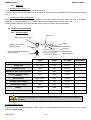
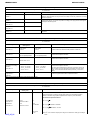
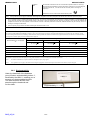
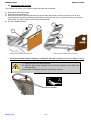
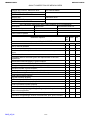
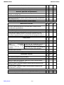
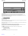
4 Le Pas du Château 85670 SAINT PAUL MONT PENIT TEL : 02-51-98-55-64 FAX : 02-51-98-59-07 Email : [email protected] Site Internet : http://www.winncare.fr EXCELYS IEX5L07/08/11 2015_05_01 580036 Anglais IEX5L07/08/11 MEDICATLANTIC 1. TRANSPORT AND STORAGE .............................................................................................................. 3 2. BED ENVIRONMENT CONDITIONS .................................................................................................... 3 3. GENERAL USE......................................................................................................................................... 3 3.1. Precautions for use ................................................................................................................................ 3 3.2. First use ..................................................................................................................................................... 5 3.3. Use .............................................................................................................................................................. 6 3.3.1. Easy Move boards............................................................................................................................... 6 3.3.2. Metal side rails ..................................................................................................................................... 7 3.3.3. Wooden barriers.................................................................................................................................. 8 3.3.4. Angled lifting pole and IV stand...................................................................................................... 8 3.3.5. Separate braking ................................................................................................................................. 9 3.3.6. Remote control .................................................................................................................................... 9 3.3.7. Leg rest ................................................................................................................................................ 10 3.4. Technical characteristics.................................................................................................................... 10 3.4.1. Electrical data..................................................................................................................................... 10 3.4.2. Equipotentiality.................................................................................................................................. 11 3.5. Putting the back rest flat ..................................................................................................................... 13 If the bed is fitted with an emergency release for the back rest (Cardio Pulmonary Resuscitation) .................................................................................................................................................. 13 4. MAINTENANCE ...................................................................................................................................... 14 4.1. Instructions for dismantling the motors ......................................................................................... 14 4.2. Maintenance ........................................................................................................................................... 14 4.3. Cleaning and disinfection ................................................................................................................... 17 4.4. Warranties ............................................................................................................................................... 19 4.5. Identification........................................................................................................................................... 19 5. CONDITIONS FOR SCRAPPING ........................................................................................................ 19 6. Easy Move BED BOARDS - 90cm WIDTH - COMPATIBLE ......................................................... 20 6.1. Bed board references for application environments 1 and 2.................................................... 20 7. COMPATIBLE ACCESSORIES ........................................................................................................... 21 8. SPECIFIC USE........................................................................................................................................ 23 8.1. Purpose of bed....................................................................................................................................... 23 8.2. General description .............................................................................................................................. 23 8.3. Specific precautions for use .............................................................................................................. 23 8.4. Electrical connection diagram........................................................................................................... 23 8.5. Use of specific elements ..................................................................................................................... 24 8.5.1. Wall stop without lining................................................................................................................... 24 8.5.2. Wall stop with lining ......................................................................................................................... 24 8.5.3. Setting wheels (cleaning)................................................................................................................ 24 8.5.4. Infrared control (option) .................................................................................................................. 24 8.5.5. Carer control box (option) .............................................................................................................. 25 8.5.6. Battery (option) .................................................................................................................................. 25 8.5.7. Flexible arm control (option).......................................................................................................... 26 8.5.8. In case of malfunction ..................................................................................................................... 26 8.6. Specific technical data......................................................................................................................... 26 8.6.1. Noise..................................................................................................................................................... 26 8.6.2. Weight .................................................................................................................................................. 27 8.6.3. Dimensional........................................................................................................................................ 27 2015_05_01 2/27 IEX5L07/08/11 MEDICATLANTIC Dear Sir/Madam, You have acquired a MEDICATLANTIC medical bed equipped with its accessories, and we thank you for your custom. Our beds and their accessories are designed and manufactured in compliance with the essential requirements of the European Directive 93/42/EEC and 2007/47/EEC. They are tested in conformity with standard EN 60601-2-52 (2010) in their commercial configurations, including the boards and accessories that we manufacture, so as to ensure you maximum safety and performance. As a result, maintenance of the contracted good’s warranty depends on compliance with the conditions for use recommended by MEDICATLANTIC and the use of original accessories, which also guarantees you safe use of the medical bed and its accessories. 1. TRANSPORT AND STORAGE For transport, the bed should be in its low position, on a pallet, and strapped and protected. The wired control and supply lead should be attached to the bed base. The head and footboards are protected and strapped to the sleeping surface. The bed should be transported upright when in its original packaging in compliance with the instructions printed on the packaging. It is strictly forbidden to stack packages weighing over 60kg/m², whatever position they are in. Before transporting or dismantling the bed, make sure the back and leg rests are fixed to the frame of the bed base. 2. BED ENVIRONMENT CONDITIONS The bed, along with the boards and accessories, must be transported, stored and used at a room temperature of between -10°C and +50°C, and relative humidity of between 30% and 75%. Atmospheric pressure between 700hPa and 1060hPa Observe the specified environmental conditions 3. GENERAL USE 3.1. Precautions for use Before use, it is essential to read these instructions carefully. They contain advice on using and looking after the bed to guarantee optimum safety. The user and staff must be trained and aware of the risks associated with using the bed, and children, confused or disorientated persons must not be allowed on it. Although the bed is conforming with Electromagnetic Compatibility, some devices may alter how it functions, in which case they must be used at a distance or not used at all. 2015_05_01 3/27 IEX5L07/08/11 MEDICATLANTIC The bed is a medical device and must not be modified under any circumstances. You must ensure its traceability, including that of the boards and its accessories. If you assemble different types of medical devices, you must conduct a risk analysis and make the CE declaration. The electric parts (jack, supply box, wired control, etc.) shall only be repaired by the manufacturer Linak. The bed is not suitable for use with an inflammable anaesthetic mixture with air or oxygen or nitrous oxide. The loads permitted (see bed characteristics) must be distributed evenly over the bed base. Do not activate all the motors at the same time when the patient is in the bed (only one motor is authorised at one time, except elevation by 2 motors or simultaneous function). After each use and while care is being administered to the patient, the brakes must be activated. We recommend putting the bed in its low position after every use and while the patient is resting, to reduce the height of falls by a confused or agitated person. Remember to lock the function(s) (if the option is available). On change of height or angle of the parts of the bed, make sure that there are no objects and no parts of the patient’s or carer’s body caught between the bed, the boards, the accessories and the ground or between the boards and base or between the cross braces. Do not sit down on the side of the back rest or leg rest if this is not flat. In the case of a prolonged more than 50 ° tilt bust semi-sitting position, it is recommended to vary the position of the person in bed every 2 hours. When the bed is being moved, keep the power lead well away from the ground and wheels. When use of an adaptor, extension lead or connection plug proves necessary, you must check that its characteristics are suitable for the bed. Connection to the supply box must be done using a mains complying with the standards in force and corresponding to a voltage of use of 230 V. The mains plug must be disconnected before the bed is moved. Do not pull on the mains leads to disconnect the mains plug. During any handling, try not to catch the leads of the motors and remote control and do not get them knotted. The wired control must be hooked to the headboard when not in use. MEDICATLANTIC prohibits the establishment of two beds in a room or in a too close environment as infrared remote command the two beds together. The condition of the leads must be checked frequently. If the slightest modification is observed, the person in charge for maintaining the bed must be contacted to carry out the necessary repairs. If repairs are required, the person in charge of maintenance must be contacted. Moreover, the telephone number of the company to be contacted for any repairs is given in this document. When using side rails, the distance between the top of the rail and the uncompressed top surface of the mattress should be at least 22 cm. For greater safety, the side rails can be adapted (see accessories). To assist patient mobility, it is possible to fit a Mobility Aid System (S.A.M.). 2015_05_01 4/27 IEX5L07/08/11 MEDICATLANTIC The cleaning instructions recommended must be complied with. Only use original parts and accessories supplied by MEDICATLANTIC to guarantee safety and maintain product conformity. The bed must not be modified. Abnormal use of the bed may damage it or cause accidents to users, in which case the warranty shall be annulled. Abnormal use means failure to comply with the precautions for use, maintenance instructions and other uses not related to the bed’s normal purpose, such as: use of the bed by several people at the same time, use outdoors, moving the bed on a slope that is steeper than 10°, etc. 3.2. First use Remove the packaging protective devices, adhesive tape, packing straps and holding clamps (see unpacking instructions on the pallet). Put the bed in the designated room, foreseeing an appropriate perimeter of use for the different functions (variable height, TR, etc.), especially if the bed has a lifting pole or side rails. Check that there is sufficient ceiling height if a lifting pole is fitted. Brake the wheels. The mains socket should remain accessible to enable the bed to be disconnected quickly. Plug in the power lead, checking that the mains comply with the standards in force and that it is suitable for the supply box voltage. Also ensure that the power lead and the remote control lead are positioned correctly to prevent any risks of getting caught between the moving parts of the bed. - Check that the bed operates properly after installing it in accordance with the check-list appended in this document. (Test all of its functions) - Users must be trained in how to use the equipment. Inform the patient and his visitors of the safety instructions to be observed. 2015_05_01 5/27 IEX5L07/08/11 MEDICATLANTIC 3.3. Use 3.3.1. Easy Move boards Installing an Easy Move bed board : Removing an Easy Move bed board : 1 2 3 1 to 2 cm 1 to 2 cm Assemble the highest board on the head side. 2015_05_01 6/27 IEX5L07/08/11 MEDICATLANTIC 3.3.2. Metal side rails To positionning the side rail. Head side Feet side 1 2 1 Insert amount of the side rail in the grip jaw on the head side of the bed. 2 Tighten the Rondo screws of the grip jaws on the bed base. To remove the side rail, in reverse operation 2 and operation 1 by pulling the release pin on the grip jaw of the head side. If the side rail is poorly positioned, safety of the patient may be endangered or a malfunctioning may occur. The side rails must not be used when the patient is a child (under 12) or if s/he is too small (≤ 146 cm). To lower the side rail. Feet side Head side To raise the side rail. Check that the side rail is locked by trying to fold it without using the release pin. There must be at least 220 mm between the top of the side rail and uncompressed mattress surface. 2015_05_01 7/27 IEX5L07/08/11 MEDICATLANTIC 3.3.3. Wooden barriers See the attached instructions for fitting the wooden side rail. To raise the side rail. Raise the top side rail with both hands until it locks. Check that it is properly slot in. To lower the side rail. Raise the top side rail with one hand. Press on the unlocking button with the other hand. Support the rail as it lowers. Repeat steps to for the other side. Check that the high guide engage in the right direction in the low guide. 3.3.4. Angled lifting pole and IV stand The lifting pole is intended to help the patient lift him/herself up and change position in the bed. It is not meant to help with transferring. 2015_05_01 8/27 IEX5L07/08/11 MEDICATLANTIC 3.3.5. Separate braking Check that the wheels are locked by trying to move the bed. If this is not done, the patient or another person who leans on the bed may fall. 3.3.6. Remote control - Carry out a test cycle when the bed is empty to familiarise yourself with the bed functions. Lifting and lowering of back rest Lifting and lowering of variable height Lifting and lowering of electric folding Simultaneous lifting and lowering of back rest and folding Key to lock a function 2015_05_01 KEY IN VERTICAL POSITION: THE FUNCTION IS UNLOCKED 9/27 TURN THE KEY SLIGHTLY TO THE RIGHT TO LOCK THE FUNCTION IEX5L07/08/11 MEDICATLANTIC 3.3.7. Leg rest Manual crank version (11): To lift, lift the leg rest using the wire handle at the end. To lower, relieve the leg rest slightly or to its maximum with the hand to release the catch, then lower the leg rest. Version with electric folding (08): Memory folding: This function keeps a position of the tibia section horizontal when the jack is activated upwards. To use this function, the 1st crank catch must be engaged when the leg rest is flat. Folding without memory: the end of the tibia section stays in contact with the bed base. 3.4. Technical characteristics 3.4.1. Electrical data Bed code Class II (double insulation) Voltage Protection level against liquid penetration Current type Frequency Operating time Protection level against electric shocks (type B) Absorbed power LINAK jack LA27 / LA24 / LA34 PROTECTION INDEX IP 66 Supply box CB6 / CB16 IP 66 230 V AC 50 HZ Connection box MJB IP 66 24V DC - Operator’s side control console ACC IP 66 24V DC - Operator’s mobile control console ACO IP 66 24V DC - Wired control HB72 / HB74 IP 66 24V DC - Lockable wired control HL72 / HL74 IP 54 24V DC - Flexible arm control FPP IP 66 24V DC - Battery BA1812- IP 66 24V DC - Infrared control HB21 IP 21 3V DC - TYPE VOLTAGE FREQUENCY 24V DC - Maximum operating time: Read the recommendations on the electrical label on the bed. Essential performances The bed will not move automatically when subject to electromagnetic disturbances within the limit of the values indicated below. 2015_05_01 10/27 IEX5L07/08/11 MEDICATLANTIC Manufacturer’s declaration and guide – electromagnetic emissions The medical bed (see references in contents) has been designed for use in the electromagnetic environment specified below. The user should ensure that it is used in such an environment. Emissions test Compliance RF emissions Electromagnetic environment - Guide Group 1 The medical bed (see references in contents) uses RF energy only for its internal functions. Therefore, its RF emissions are very low and are not likely to cause any interference in nearby electronic equipment. Class B The medical bed (see references in contents) can be used in all domestic environments, including those directly connected to the public low-voltage power supply network that supplies buildings for domestic purpose. Class A [] CISPR 11 RF emissions CISPR 11 Harmonic emissions EN 61000-3-2 Voltage fluctuations / Flicker Applicable EN 61000-3-3 RF emissions Compliant The medical bed (see references in contents) has not been designed for connection to other equipment. CISPR 14-1 Manufacturer’s declaration and guide - electromagnetic immunity The medical bed (see references in contents) has been designed for use in the electromagnetic environment specified below. The user should ensure that it is used in such an environment. IEC 60601 Immunity test Compliance level Electromagnetic environment - Guide L Severity level Electrostatic discharge ± 6 kV contact EN 61000-4-2 ± 8 kV air ± 6 kV contact ± 8 kV air Floors should be wood, concrete, or ceramic tile. If floors are covered with synthetic material, the relative humidity should be at least 30%. Electrical fast transients ±2 kV for feeders ±2 kV for feeders The quality of the main power supply must be the same as for a typical commercial or hospital environment. ±1 kV for input/output lines ±1 kV for input/output lines Differential mode ± 1 kV Differential mode ± 1 kV Common mode ± 2 kV / EN 61000-4-4 Surges EN 61000-4-5 Voltage dips, short interruptions and voltage variations EN 61000-4-11 • <5% UT - for 10 ms • <5% UT – for 10 ms • 40% UT - for 100 ms • 40% U T - for 100 ms • 70% UT - for 500 ms • 70% UT - for 500 ms • <5% UT - for 5 s • <5% UT - for 5 s Power frequency magnetic field (50/60 Hz) 3 A/m The quality of the main power supply must be the same as for a typical commercial or hospital environment. The quality of the main power supply must be the same as for a typical commercial or hospital environment. If the user of the medical bed (see references in contents) wants to be able to continue to use the bed during interruptions in the main power supply, it is recommended that the bed be powered by a converter or battery. 3 A/m Power frequency magnetic fields should be at levels characteristic of a location in a typical commercial or hospital environment. NB: UT is the nominal value of power voltage applied during the test. Manufacturer’s declaration and guide - electromagnetic immunity The medical bed (see references in contents) has been designed for use in the electromagnetic environment specified below. The user should ensure that it is used in such an environment. Immunity test IEC 60601 Compliance level Electromagnetic environment - Guide Severity level Portable and mobile RF communications equipment should be used no closer to the medical bed (see references in contents), including leads, than the recommended separation distance, calculated using equations applicable to the frequency of the transmitter. Recommended separation distance Conducted RF 3 Vrms EN 61000-4-6 150 kHz to 80 MHz Radiated RF 3 V/m EN 61000-4-3 80 MHz to 2.5 GHz 3V d = 1,17 P 3 V/m 80 to 800 MHz d = 1,17 P 80 MHz to 800 MHz d = 2,33 P 800 MHz to 2.5 GHz 2 to 2.5 GHz 10 V/m 2015_05_01 where P 11/27 is the maximum output power rating of the transmitter in watts (W) according to IEX5L07/08/11 MEDICATLANTIC 800 MHz to 2 GHz the transmitter manufacturer and d the recommended separation distance in meters (m). The field strengths transmitted by fixed RF transmitters, determined by an electromagnetic a measurement of the site , must be less than the conformity level in each range of frequencies. Disturbances can occur near devices marked with this symbol: Note 1 At 80 MHz and 800 MHz, the upper frequency range applies. Note 2 These guidelines may not apply in all situations. Electromagnetic propagation is affected by absorption and reflection from structures, objects and people. A Field strengths from fixed transmitters, such as base stations for radio (cellular/cordless) telephones and land mobile radios, amateur radio, AM and FM radio broadcast and TV broadcast cannot be predicted theoretically with accuracy. To assess the electromagnetic environment due to fixed RF transmitters, an electromagnetic site survey should be considered. If the measured field strength in the location in which the medical bed (see references in contents) is used exceeds the applicable RF compliance level above, the normal operation of the bed must be checked. If abnormal performance is observed, additional measures may be necessary, such as reorienting or relocating the medical bed. B Over the frequency range 150 kHz to 80 MHz, field strengths should be less than 3 V/m. Recommended separation distances between portable and mobile RF communications equipment and the medical bed (see references in contents) The medical bed (see references in contents) is intended for use in the electromagnetic environment in which radiated RF disturbances are controlled. The user of the bed can help prevent electromagnetic interference by maintaining a minimum distance between portable and mobile RF communications equipment (transmitters) and the bed as recommended below, according to the maximum output power of the communications equipment. Separation distance according to frequency of transmitter m Rated maximum power of transmitter 150 kHz to 80 MHz 80 MHz to 800 MHz 800 MHz to 2.5 GHz d = 1,17 P d = 1,17 P d = 2,33 P 0.01 0.12 / 0.116 0.12 / 0.116 0.23 / 0.233 0.1 0.37 / 0.316 0.37 / 0.366 0.74 / 0.736 1 1.17 / 1.16 1.17 / 1.16 2.33 / 2.33 10 3.70 / 3.66 3.70 / 3.66 7.37 / 7.36 100 11.70 / 11.6 11.70 / 11.6 23.30 / 23.3 W For transmitters rated at a maximum output power not listed above, the recommended separation distance d in meters (m) can be estimated using the equation applicable to the frequency of the transmitter, where P is the maximum output power rating of the transmitter in watts (W) according to the transmitter manufacturer. Note 1 At 80 MHz and 800 MHz, the separation distance for the higher frequency range applies. Note 2 These guidelines may not apply in all situations. Electromagnetic propagation is affected by absorption and reflection from structures, objects and people. 3.4.2. Equipotentiality Under the head-half of the bed base you will find an equipotentiality socket , identified by the label , enabling you to connect any electromedical devices. The leads of these devices must pass through the head end and not the sides. 2015_05_01 Label Equipotentiality 12/27 IEX5L07/08/11 MEDICATLANTIC 3.5. Putting the back rest flat In the event of a power cut or failure, flatten the back rest as follows: a) Disconnect the power supply. b) Dismantle the headboard . c) Stand at the head of the bed and take hold of the back rest handle with one hand. Push or lift to compensate the pressure exerted by the patient and unhook the clip by the connecting rod with the other hand. The back rest jack will then pivot downwards. d) Put the headboard back. 2 2 1 3 3 1 Version with handle on the back rest Version without handle on the back rest If the bed is fitted with an emergency release for the back rest (Cardio Pulmonary Resuscitation) 1) Grasp the back rest with one hand. 2) With the other hand, activate one of the two handles on the back rest while lowering. If the handle is released, the back rest will stop moving. Release handles 2015_05_01 13/27 IEX5L07/08/11 MEDICATLANTIC 4. MAINTENANCE 4.1. Instructions for dismantling the motors Disconnect the 230 volts connection before dismantling. • • • • Dismantle when the bed is empty or in the side position. If dismantling in any other position, keep a firm hold of the moving parts to avoid any shearing. Unblock the safety clips , unplug the motor leads, and remove them from the securing seals. Put the motors back in place and put in the same direction as at the beginning. Safety clip 4.2. Maintenance Quality control of medical beds will be made by technical staff or trained biomedical and taking into account the normal conditions of use specified in the user guide, on a bed with its specific security barriers. The bed must be available to perform all quality control at least once a year, but also on special request and corrective maintenance on the performance that could be affected by the intervention. However, to save time this may be associated with preventive maintenance. In this case, it is not useful to make a further examination of already controlled performance. RECOMMENDATIONS FOR PREVENTIVE MAINTENANCE: Preventive maintenance should be carried out in accordance with our specifications and at least once a year by the organisation or person who installed the bed. Between two maintenance sessions and at least once a year, the following should be carried out: - Verification that the electrical leads are connected all along the metal jambs to prevent shearing of these leads when the variable height is being activated. - Verification that all of the electrical leads and plugs are in good condition. Replacement if there is the slightest alteration (wear, shearing, damage, etc.). - Verification of the external appearance (traces of damp and good overall condition of protective covers in particular) and that the motors and jacks function properly. - Verification that the bed is in good working order (test all functions). - Verification that the frame, bed base and mechanical joints are all in good condition. When maintenance is carried out at the patient’s home as part of a long-term contract, the installer must also: - Check that the bed is properly installed (check to see that there hasn’t been any modification contrary to the safety instructions made by the user since the bed’s installation). - Remind the users of the safety instructions. - All installation and preventive maintenance operations must be recorded. See table model below. This record must be kept in a designated area throughout the bed’s lifetime. 2015_05_01 14/27 IEX5L07/08/11 MEDICATLANTIC QUALITY INSPECTION OF MEDICAL BEDS IDENTIFICATION OF MEDICAL BED ESTABLISHMENT CATEGORY TYPE MODEL TRADEMARK SERIAL NO. SERVICE SITE INVENTORY NO. DATE OF MANUFACTURE TEST DEVICES CHECKED AND CONFORMING WITH STANDARDS Description Type/model Identification/serial no. Mass continuity tester Dielectrimeter Fault current to patient Qualitative aspects VISUAL CHECKS General condition User’s manual available Headboard and footboard present Good overall condition (head and footboards, bed corners, protective stops) General cleanliness Acceptable state of corrosion given the requirements of the user department Identification/label/serigraphy in good condition Mechanical condition Lifting pole in good condition (positioning and strap) Mechanical leads in good condition Sleeping surface in good condition (bed base) Boards lock and tighten well (head and footboards) Chest rest functions properly Leg rest functions properly Half-seated position functions properly Manual leg rest functions properly TR/RTR positions function properly Bed base extension functions properly Castors function properly (pivoting, rolling, etc.) including the steering castor where applicable. Bed immobilises properly (castor brakes, etc.) Verification of tightenings, diverse nuts and bolts, pins, pivot, IV stand 2015_05_01 15/27 NA (1) YES NO IEX5L07/08/11 MEDICATLANTIC Qualitative aspects NA (1) YES NO NA (1) YES NO NA (1) YES NO NA (1) YES NO Verification that welds are in good condition Absence of sound disturbances (squeaking, lubrications) Electrics, hydraulics and pneumatics Electrical leads, plugs and connectors are in good condition (not sheared, not caught, etc.) Electrical parts in good condition (leads, motors, boxes, etc.) Hydraulic and pneumatic parts in good condition (pumps, compressors, jacks, dampers, etc.) Remote controls, displays and lights in good condition Bed-specific side rails The rails in place and specific to the bed and/or comply with the manufacturer’s specifications Properly positioned and secured Side rail locking functions properly in raised position Check that the height measured from the top of the barrier to the uncompressed mattress surface, excluding therapeutic mattresses, is more than or equal to 220 mm (complies with the standard in force) 2 Safety check Locking of operational functions Inactivation of variable height control pedals Cardio Pulmonary Check that the headboard extracts or Resuscitation (CPR) retracts properly in an emergency emergency flattening of the Check that the chest rest emergency back rest flattening function works properly Withstands jack load well Visual and sound alarms in good working order Quantitative aspects Bed functions properly using the battery Check the scale of movements Maximum angle when propped = Maximum angle of specifications claimed by the manufacturer (± 2°) Maximum height = Maximum height of specifications claimed by the manufacturer (± 20 mm) Minimum height = Minimum height of specifications claimed by the manufacturer (± 20 mm) Electrical safety Electrical safety inspection (Values comply with EN 60601-1) 2015_05_01 16/27 IEX5L07/08/11 MEDICATLANTIC Comments Conclusion Operational (is the safety of the patient, carers and technical staff at risk?) Plan of action (see comments) 3 Recommended date of next quality inspection OPERATOR NAME Establishment DATE Signature YES NO 1 Not Applicable 2 If the height measured does not comply with the standard, the health manager responsible for correct application must be informed. Failure to comply is not a criterion for a non-operational status. 3 The manager decides on the actions to take and which people to contact depending on the results of the quality inspection and the comments made. 4.3. Cleaning and disinfection High-pressure cleaning is forbidden. Unplug the mains lead. Check that all the electrical parts are connected together. All the sockets of the supply box must be used, otherwise its watertightness is not guaranteed. Clean the electric covers of the jacks and wired control straightaway if any bodily fluids, particularly urine, have sprayed on to them. The medical bed is a non-critical appliance requiring “Low Level” disinfection. We draw your attention to the fact that the recommendations below are drawn up according to the rules of good practice but are not a protocol. Contact the hospital hygiene department. AIM To recondition the bed and prevent the transmission of germs from one patient to another. To eliminate all organic soiling by: - physical action (cleaning) - chemical action (disinfection) INDICATION Physical and bacteriological cleanliness of the bed and its accessories 2015_05_01 17/27 IEX5L07/08/11 MEDICATLANTIC EQUIPMENT Microfiber wipes Detergent or Detergent-Disinfectant (Surface DD with CE mark) and surface Disinfectant (Chlorine substances, alcohol base < 30%) Attention: DD products and Javel water must not be used undiluted. A remanence time must be applied according to the disinfectant manufacturer’s instructions (the drying time without human presence is often the same as the remanence time) SANIVAP steam appliance with accessories TECHNICAL - - Daily maintenance with a surface DD product in one operation. Maintenance when the patient leaves, or periodically, by the process known as Bio cleaning observing the 3 operations: o Cleaning is done by means of a cloth soaked in a surface detergent or Detergent-Disinfectant (DD) solution o Rinsing is done with cloth rinsed in clean water o Disinfection is done by means of a cloth soaked in a surface disinfectant solution. Specific maintenance by specialist contractors after removal of the bed from the establishment: o Dispose of the packaging after decontamination of the inside by spraying with a DetergentDisinfectant solution o Bio cleaning operation, or, o Steam cleaning (accessory with microfiber band) of the flat surfaces and the base slats. Change the washing mops regularly to prevent water accumulating. Clean the parts that are difficult to access with a steam nozzle (wheels, hinges after opening, corners, etc.). For tubes, use the steam nozzle with a microfiber cloth. Never direct the nozzles onto electrical boxes or actuators. o Dry hinges with compressed air o Attention: Disinfect jacks, electrical boxes and remote controls with a microfiber cloth soaked in disinfectant. Do not rinse or wipe. Check the operation of all the bed functions Repair if necessary Pack in thermoplastic film Attention: In the event of additional precautions (Contact precautions, Droplets or Air), apply the measures recommended by the hospital hygiene department - The use of a Javel water solution of more than 5000ppm (0.5% of active chlorine) should be justified by a microbiological risk and only applied for the required time (Risk of ageing of some materials, especially their colour). - The concentration of alcohol-based surface disinfectant solutions should be less than 30%. Note: The use of the terminal disinfection process is compatible with the medical bed and its accessories. - Product for external use. Do not swallow, keep away from heat sources and avoid contact with eyes. 2015_05_01 18/27 IEX5L07/08/11 MEDICATLANTIC 4.4. Warranties All of our products carry a warranty against any manufacturing defect, provided the normal conditions for use and maintenance are complied with. Labour costs due to changes in structures or parts under warranty are not taken into account. Please refer to the standard terms of sale for the specific terms of warranty for each product. Every time you contact us for possible maintenance, you must quote us the information on the bed identification label and on the electric parts if these are concerned. Original parts shall be supplied for replacement, within the term of warranty, by our customer sales network determining the beginning of the term of warranty. Defective parts must be returned to ensure proper application of this warranty and also to avoid any invoicing. 4.5. Identification Manufacturer Product identification CE marking Refer to user’s manual Manufacturer's address Serial number and date of manufacture Refer to user’s manual xxx kg yyy kg Maximum patient weight Safe operational load 5. CONDITIONS FOR SCRAPPING The product must be scrapped if the main requirements are no longer met, particularly when the product no longer has its original characteristics and has not been subject to corrective action during the manufacturing process. Measures should therefore be taken to ensure that the bed is no longer used for the purpose it was originally intended. 2015_05_01 19/27 IEX5L07/08/11 MEDICATLANTIC 6. Easy Move BED BOARDS - 90cm WIDTH - COMPATIBLE Item Reference MEDIDOM II Easy move (2) (4) COTE DE LUMIERE Easy Move DAGONE Easy Move ELEGANTTI Easy Move LOUIS PHILIPPE Easy Move (1)(2) CARMEN with Easy Move wooden barriers (2) COTE DE LUMIERE with Easy Move wooden barriers (2) VAL DE VIE with Easy Move wooden barriers (2)(4) MEDIDOM Easy Move (2) (4) WINNEA® Easy Move (3) AUZENCE II Easy Move WINNEA® CIC Easy Move (1) ABELIA II Easy Move CARMEN II with Easy Move wooden barriers (2) MADELIA II Easy Move CARMEN II Easy Move VAL DE VIE Easy Move (4) P318-00 P360-00 P388-00 P414-00 P415-00 P506-00 P549-00 (1) (2) (3) (4) P552-00 P600-00 P609-00 P611-00 P615-00 P616-00 P620-00 P624-00 P625-00 P704-00 Bed board incompatible with the XPRESS transport kit Long pan option incompatible with the XPRESS transport kit Emergency removable option incompatible with the XPRESS transport kit Board incompatible with the centralised brake option of the ALDRYS bed The blanket hoop option is incompatible with the XPRESS transport kit, XPRIM III and AERYS bed 6.1. Bed board references for application environments 1 and 2 Item Reference WINNEA HAND RAILS (Easy move) WINNEA CIC BOARDS (Easy Move) P609-00 P615-00 Only accessories and boards supplied by MEDICATLANTIC guarantee safe use. 2015_05_01 20/27 IEX5L07/08/11 MEDICATLANTIC IV stand, 2 hooks A1700xx Chrome-plated urine bottle A5800 holder Telescopic IV stand, 2 hooks A8400xx Lifting pole for Kalin Pitchoune A165-00 bed Chrome-plated wall-mounted A193-00 basin holder Remote-control lead holder A230-00 Epoxy urinal holder A260-00 Excelys wall stop A551-00 A552/557- Skirt for Excelys and L.P. bed A553/555- Skirt for 120/140 and L.P. beds A554/556- Skirt for 160 and L.P. beds Full length KALIN side rails A562-00 KALIN bed skirt A563-00 A564/565- KALIN EPOXY side rail Support handle A575-00 PVC-wrapped wooden side rails A579-00 (2) wood side rails (2) Solid A580-00 S.A.M. EVOLUTION PLUS A613-00 A616/617- S.A.M. ACTIV Easy Move base extension A621-00 Angled lifting pole A622-00 Chromed angled lifting pole A623-00 Bed loading kit A626-00 Transport kit Transtolit A627-00 A630-00 Bed base extension (width A631-00 Bed base extension (width A632-00 Bed base extension (width Médicalys wall stop A633-00 Kit for side loading bed A634-00 AERYS wall stop A636-00 A637/638- EPOXY side rail A639/640- Chrome barrier A645/646- S.A.M. EVOLUTION A647/648- S.A.M. ERGONOM PLUS A649/650-00 S.A.M. ERGONOM A651/652- S.A.M. ERGONOM LIGHT A653-00 Kit for side loading bed AERYS Skirt for 90cm bed A654-00 Skirt for 90 cm bed FC A655-00 Skirt for 90 cm bed LP A656-00 Skirt for 90 cm bed FC LP A657-00 Blanket hoop (2) Pxxx Stainless steel intravenous stand on S0200 base Lifting pole on U shaped base, fixed height Y0200 1 8 NA 8 75 NA NA NA NA NA NA NA NA NA NA NA NA NA NA NA NA 75 75 NA NA NA NA NA NA NA NA NA NA NA NA NA NA NA NA NA NA NA 15 8 2 2 2 2 2 2 DUO 160 IXL-IXX-DUO 140 IXL-IXX 120 2 2 2 2 2 2 2 2 2 2 2 2 2 2 2 1 1 1 1 1 1 1 2 2 75 21/27 AERYS-120 2 requires the centralised braking kit 2 incompatible with Bed base extension 2015_05_01 PITCHOUNE MEDICALYS 2nd G AERYS EXCELYS ALDRYS OSIRYS XPRESS 2nd G Des. XPRIM III Ref. Charge maxi (kg) 7. COMPATIBLE ACCESSORIES 2 IEX5L07/08/11 MEDICATLANTIC Only accessories and boards supplied by MEDICATLANTIC guarantee safe use. Mattress Observe the mattress dimensions prescribed. See user guide Width of base in cm 80 90 120 140 IXL 140 DUO 160 DUO Characteristics of compatible mattresses Width 76 cm minimum with a high-resilience foam of 34 kg/m³ minimum, height between 14cm min. and 15 to 17cm max. Width 86 cm minimum with a high-resilience foam of 34 kg/m³ minimum, height between 14cm min. and 15 to 17cm max. Width 116 cm minimum with a high-resilience foam of 34 kg/m³ minimum, height between 14cm min. and 15 to 17cm max. Width 136 cm minimum with a high-resilience foam of 34 kg/m³ minimum, height between 14cm min. and 15 to 17cm max. Width 68 cm minimum with a high-resilience foam of 27 kg/m³ minimum, height between 14cm min. and 15 to 17cm max. Width 78 cm minimum with a high-resilience foam of 27 kg/m³ minimum, height between 14cm min. and 15 to 17cm max. Incompatible mattresses can pose RISKS. 2015_05_01 22/27 IEX5L07/08/11 MEDICATLANTIC 8. SPECIFIC USE 8.1. Purpose of bed The beds are not designed for children under 12 or height under 146cm, or for any other purpose apart from those stipulated below. Depending on their configuration, the beds are intended for home use (HAD – MAD), EPHAD and HPA. The beds with the emergency flattening option of the back rest are designed for medical care centres. 8.2. General description CPR handles Angled lifting pole slots Slatted back rest Slatted leg rest Headboard Bed base Footboard IV stand slots Leg rest handle Base and cross Castors 8.3. Specific precautions for use The bed should not be used as a stretcher. 8.4. Electrical connection diagram Forward slant jack Leg rest jack Backrest jack Variable height jack Remote control 1 2 3 4 HB Control box CB6S634 2015_05_01 23/27 IEX5L07/08/11 MEDICATLANTIC 8.5. Use of specific elements 8.5.1. Wall stop without lining 8.5.2. Wall stop with lining 8.5.3. Setting wheels (cleaning) Raising / lowering of the backrest Raising / lowering of adjustable height Raising / lowering of electrical leg lift with fold at knee break Simultaneous raising / lowering of leg lift with fold at knee break and Trendelenburg Pilot light Setting wheels When the bed is on its wheels (having a cleaning function, not for the stretcher), a beep warns you not to forget to press up to block the bed on its feet. Lock the function after setting the bed on his skates. 8.5.4. Infrared control (option) The infrared remote control is always associated with the housing caregiver. This in order to lock the height function variable and therefore on castors. MEDICATLANTIC prohibits the installation of two beds in a room or in a too close space because infrared remote control will command the two beds together. 2015_05_01 24/27 IEX5L07/08/11 MEDICATLANTIC Raising / lowering of the backrest Pilot light Setting wheels Raising / lowering of electrical leg lift with fold at knee break Raising / lowering of adjustable height Simultaneous raising / lowering of leg lift with fold at knee break and Trendelenburg Simultaneous raising / lowering of leg lift with fold at knee break, back rest and Trendelenburg 8.5.5. Carer control box (option) To activate the functions, press the « arrow » key (up or down) at the same time as the desired function. Leg lift Raising back Adjustable height Back slant / forward slant Chair position Simultaneous functioning of the raising back and leg lift Flatten Flatten and forward tilt at the same time To lock functions (raise back, variable height, leg rest, back tilt, forward tilt), press the « key » key and the key for the function to be locked. 8.5.6. Battery (option) The (optional) back-up battery enables you to perform 3 complete cycles when the bed is not connected to the mains. After these 3 cycles, a beep warns you that you need to to re-connect the bed to the mains to recharge the battery. However, you still have one more complete cycle of autonomy without reconnecting. Operating instruction: A new battery needs to be charged for 24 hours before using it for the first time. The purpose is to have batteries in their maximum state of charge and hence increase their service life. 2015_05_01 25/27 IEX5L07/08/11 MEDICATLANTIC Storage conditions: Batteries should be charged every 3, 6 or 9 months depending on the storage temperatures. Storage temperature 20°c or less 20 – 30°c 30 – 40°c Charging interval Every 9 months Every 6 months Every 3 months 8.5.7. Flexible arm control (option) The flexible arm option is always combined with the carer control box. The flexible arm support is fixed with 2 rondo screws on the long side of the bed base. The functions can be locked using the carer control box. Electric plication raise / lower Backrest raise / lower Locking indicator light Variable height raise / lower The flexible arm connects to the connection box The flexible arm is fixed to one of the long sides of the bed observing a minimum distance of 63 cm from the panels or any accessory. The arm should not make more than 2 turns in relation to its support to avoid damaging the connecting cable. Fitting a lifting handle on the same side as the flexible arm control is not allowed. Use the clip and the pin for the passage of the flexible arm control 8.5.8. In case of malfunction The control box can put itself in default (bad connection, cable fault, actuator fault ...). In this case the movements are impossible and the control box makes short and discontinuous beeps at the push of a button the remote control. It is necessary to reset the electrical assembly : 1-Simultaneously press the two buttons of backrest and hold until the end of a long and discontinuous beep 2-Raise the height variable actuator to the maximum (initialization of the actuator). 8.6. Specific technical data 8.6.1. Noise The maximum sound level is measured at 53 dBa. 2015_05_01 26/27 IEX5L07/08/11 MEDICATLANTIC 8.6.2. Weight Normal load in use: 215 kg (Patient 180 kg, Mattress 20kg. Accessories 15kg) Bed, version electric folding leg rest (without boards)……………………………..………... 93 kg Bed, version manual crank leg rest (without boards)……………………………………...… 90 kg 8.6.3. Dimensional MEDICATLANTIC recommends the use of a patient lift or a dining table bases with less than 120 mm high. Version 11 672 mm 947 mm 739 mm 847 mm 394 mm 553 mm Version 08 2015_05_01 27/27