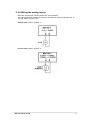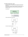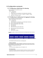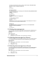
1
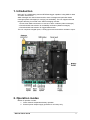
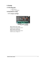
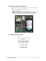
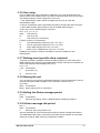
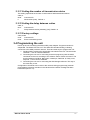
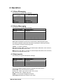
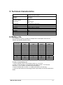
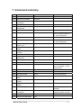
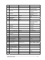
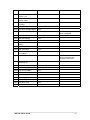
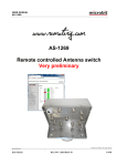
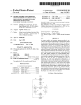
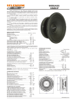
BSC-50-E
Battery powered RTU/Data Logger
User Guide
Contents
1. Introduction
2. Operation modes
3. Setup
3.1 Packing list
3.2 Hardware setup
3.2.1 Jumper settings
3.2.2 SIM card & Battery installation
3.2.3 Wiring the digital inputs
3.2.4 Wiring the analog inputs
3.3 Configuration commands
3.3.1 Configuring a digital input for alarming
3.3.2 Configuring an analog input for alarming
3.3.3 Setting alarm message texts
3.3.4 Selecting alarm messages for a DI event
3.3.5 Selecting alarm messages for an AI event
3.3.6 User setup
3.3.7 Defining event specific alarm recipients
3.3.8 Naming the unit
3.3.9 Setting the Status message period
3.3.10 Status message idle period
3.3.11 Setting the number of transmission retries
3.3.13 Factory settings
3.4 Programming the unit
4. Operation
4.1 Alarm Messaging
4.2 Status Messaging
4.3 Data transfer
5. Technical characteristics
6. Battery life
7. Command summary
3
3
4
4
7
9
10
10
10
10
11
11
12
Disclaimer
• While every effort has been made to ensure that the information in this guide is
accurate and complete, no liability can be accepted for any errors or ommissions.
• Infinite Ltd reserves the right to change the specifications of the hardware and
software described in this guide at any time without prior notice.
• No part of this guide may be reproduced, transmitted, stored in fixed or removable
media or translated into any language in any form without the prior written
permission of Infinite Ltd.
• Infinite makes no warranties for damages resulting from corrupted or lost data
due to malfunction of the hardware or the software.
Version: 2.0
Copyright © 2009 - 2011 – Infinite Informatics Ltd
All rights reserved.
BSC-50-E User Guide
2
1. Introduction
BSC-50-E is a GSM battery powered RTU/Data logger capable of using SMS for data
and alarm transmission.
SMS messages are used for data transfer, alarm messages and periodical health
messages (status messages) for verifying unit availability. The unit supports discrete
recipient alarming for several users. SMS messaging includes:
1. Event driven SMS transmission in case of an alarm condition (Alarm messages).
2. Periodical SMS transmission for availability verification (Status messages).
3. Periodical SMS transmission for logged data transfer.
The unit comprises 4 digital inputs, 2 analog inputs and a transducer excitation output.
2. Operation modes
Modes of operation include:
1. Power network independent battery operation.
2. External power adaptor supply operation for unit setup only.
BSC-50-E User Guide
3
3. Setup
3.1 Packing list
1. BSC-50-E unit
2. Lithium Thionyl Battery
3.2 Hardware setup
3.2.1 Jumper settings
JMP3: Analog input 1 mode:
Position C (1-2): Current 0-20/4-20mA
Position V (2-3): Voltage 0-1V
JMP5: Analog input 2 mode:
Position C (1-2): Current 0-20/4-20mA
Position V (2-3): Voltage 0-1V
BSC-50-E User Guide
4
3.2.2 SIM card & Battery installation
•
Open the unit enclosure by unscrewing the plastic screws on the enclosure’s
top.
•
Insert the SIM card into the SIM card holder.
•
Install the Lithium battery.
WARNING: Pay attention to the correct polarity! The right polarity is
marked up on the battery holder. Inverse polarity will stress the low power, low
voltage rectifying circuits in the unit and will lead to hardware failure.
3.2.3 Wiring the digital inputs
BSC-50-E User Guide
5
3.2.4 Wiring the analog inputs
BSC-50-E incorporates 2 analog inputs with 10 bit resolution.
The input signal mode (voltage or current) is selectable by means of jumpers JP3 for
AI1 and JP5 for AI2 (see 3.2.1).
Voltage input: JMPx in position ‘V’.
Current input: JMPx in position ‘C’.
BSC-50-E User Guide
6
3.2.5 Wiring the Excitation output
BSC-50-E incorporates a 12VDC excitation output to supply power to external analog
transducers. Low power 0-1V transducers are recommended for preserving longer
battery lifetime.
The sensor supply is switched according to the analog input sampling rate (one sample
per minute). The unit performs 6 consecutive readings for every sample, thereby
neglecting the maximum and minimum values and calculates the average of the
remaining four values.
0-1V transducer:
Two Wire 0-20/4-20mA Sensor (BSC-50-E):
Four Wire 0-20/4-20mA transducer:
BSC-50-E User Guide
7
3.3 Configuration commands
3.3.1 Configuring a digital input for alarming
The DI configuration command structure is:
1100,n,s,a,d
1100: Command ID
n:
DI number (1-4)
s:
DI name (Text: 0-15 characters, may include space characters)
a:
Transition selection (0: No alarm, 1: positive, 2: negative, 3: Both)
d:
Delay time in seconds (0-255)
3.3.2 Configuring an analog input for logging & alarming
The AI configuration command structure is:
1200,n,s,ssl,ssh,sl,sh,al,ah,u,d
1200: Command ID
n:
AI number (1-2)
s:
AI name (Text: 0-15 characters, may include space characters)
ssl: Sensor scale low (Row value 0-4095)
ssh: Sensor scale high (Row value 0-4095)
sl:
User scale low
sh: User scale high
al:
Alarm limit low in physical scale values
ah: Alarm limit high in physical scale values
u:
Physical unit
d:
Alarm delay in minutes
The following table contains the scale and sensor low/high values for the common
ranges:
Transducer
AD592
Scale
0-1V
0-20mA
4-20mA
-25°C - 95°C
Sensor low
0
0
819
2742
Sensor high
4095
4095
4095
4069
Gain
4.095
4.095
4.095
4.095
*AD592 Requires a 2.7K resistor between AI+ and AI-. Set for voltage measurement.
Three additional parameters refer to all analog inputs:
AI Alarm Deadband
The parameter defines the alarm deadband (hysteresis) for the analog channels.
Alarm deadband is a small range of the total scale, where the alarm state remains
indifferent, by registering the last value.
1290,d
d: 0-50 for an alarm deadband of 0-5% in steps of 0.1%.
AI sampling delay
The parameter defines an idle period between switching on/off the excitation and
registering the measurements of the analog inputs. This option should be set
BSC-50-E User Guide
8
according to the transducer power up delay for stable reading. The value of this
parameter affects strongly the battery life.
1291,d
d: 0-255 sec
AI sampling interval
The parameter defines the AI sampling period. The value of this parameter affects
strongly the battery life.
1292,p
p: 1-255 min
AI logging rate
The parameter defines the AI logging rate.
1300,n
n: 0-255, number of samples.
n=0 disables logging.
Example:
1300,4 instructs the unit to log every fourth sample. If the sampling rate is every 15
minutes then the unit will log one sample per hour.
Sending rate
The parameter defines the logged data transmission rate. The value of this
parameter affects the battery life.
1310,p
p: 0-255 hours
3.3.3 Setting alarm message texts
You can set up to 128 custom text messages to be announced in an SMS alarm as a
descriptive reason instead of the default text. The command for configuring a text
message is:
0630,ID,s
0630: Command ID
ID: Message ID (1-128)
s:
Message text (0-64 characters, may include space characters)
3.3.4 Selecting alarm messages for a DI event
Two alarm messages can be associated to a DI alarm event. One for M2M recipients
(e.g. containing an ASCII command for a remote SCOM device) and a second for
phone recipients:
110x,n,ID
110x: Command ID, 1102 for M2M, 1101 for Phone recipients
n:
Input number (1-4)
ID: Message ID (1-128)
3.3.5 Selecting alarm messages for an AI event
Two alarm messages can be associated to a DI alarm event. One for M2M recipients
(e.g. containing an ASCII command for a remote SCOM device) and a second for
phone recipients:
120x,n,ID
120x: Command ID, 1202 for M2M, 1201 for Phone recipients
n:
Input number (1-4)
ID: Message ID (1-128)
BSC-50-E User Guide
9
3.3.6 User setup
Up to 20 SMS users can be declared in a BSC-50-E unit. Only declared users can
interact (send, receive SMS) with the unit. BSC-50 features three levels of user rights.
The following options can be configured for each user:
1. User administration option. Status messages are sent only to users with
administration rights.
2. Device configuration option. Represents the right to configure the BSC-50 device.
3. Alarm SMS recipient option. Marks a user as an SMS alarm recipient.
A new user can be created using the command:
0500,id,n,p,c1,c2,c3
0500:
Command ID
id:
User ID (1-20)
n:
User name (0-15 characters)
p: Phone number (3-15 characters)
c1:
User administration rights (0 for ‘No’ 1 for ‘Yes’)
c2:
Device configuration rights (0 for ‘No’ 1 for ‘Yes’)
c3:
Alarm SMS recipient (0 for ‘No’ 1 for ‘Yes’)
c4:
M2M, User is a M2M device (0 for ‘No’ 1 for ‘Yes’)
Additional commands to configure, and delete a user are available for user
administration.
3.3.7 Defining event specific alarm recipients
A special command is available to define the SMS recipients for each alarm event.
M2M recipients will receive the associated M2M message, while phone recipients will
receive the respective text message (See 3.2.3).
1103,n,id
1102:
n:
id:
Command ID
DI number (1-4)
User ID (1-20)
3.3.8 Naming the unit
You can specify a unit name for identification purposes. The unit name will be used in
the alarm and status SMS messages. The command to name the unit is:
0300,Name
0300: Command ID
Name: Device name (up to 15 characters)
3.3.9 Setting the Status message period
0650,n
0650:
n:
Command ID
Period (0-99), [Days], Value ‘0’ disables status messaging, Default: 7
3.3.10 Status message idle period
0651,n
0650: Command ID
n:
Period (0-180), [sec], Default: 120
Use this parameter to set an idle time period after the Status message transmission.
The GMS Modem will remain connected to the GSM Provider network for this period,
waiting for receipt of SMS containing configuration updates.
BSC-50-E User Guide
10
3.3.11 Setting the number of transmission retries
This setting represents the number of retries after a SMS transmission failure.
0640,n
0640:
n:
Command ID
Send retries (0-99), Default: 3
3.3.12 Setting the delay between retries
0641,n
0641:
n:
Command ID
Delay between retries (0-65535), [sec], Default: 10
3.3.13 Factory settings
0183,0183
0183:
0183:
Command ID
Extra command argument
3.4 Programming the unit
Power up the unit connecting the external DC power adaptor. Program execution is
suspended. The Status LED turns off. The GSM LED will start blinking, indicating
connection to the GSM provider’s network. There are three ways to program the unit:
1. Sending SMS containing the appropriate commands to the unit. The semicolon
character ‘;’ acts as command delimiter.
2. Connecting the unit to a PC and using a terminal program to pass the ASCII
commands to the unit, according to the scheme: atsms=”ASCII command”. The
terminal settings should be: Baud rate: 115200 bps, Data bits: 8, Parity: none,
Stop bits: 1, Flow control: Hardware.
3. Connecting the unit to a PC and using the WA Manager software. This way is
the most easy to use.
Configuration commands can be sent to the unit both during program stop (external
power adaptor operation) and also in the idle time after a status message has been
transmitted (see 3.3.10).
BSC-50-E User Guide
11
4. Operation
4.1 Alarm Messaging
The following is a typical Alarm message:
Message
contents
BSC-50
ALARM MESSAGE
DI 1
Earth Fault
Item description
Unit Name
Fixed Header
Input Name
Alarm message
4.2 Status Messaging
The following is a typical Status message:
Message contents
BSC-50
STATUS MESSAGE
ON
TOTAL:
SQ:
BER:
Item description
Unit Name
Fixed Header
Operation Status
n
ERR:x, MIN:y, MAX:y, AVG:y
ERR:x, MIN:y, MAX:y, AVG:y
SMS Status messages are sent only to users with the Admistnistrator rights.
The Status message contains the information regarding the GSM signal quality.
The information includes the following fields:
TOTAL: n, number of samples
SQ: Signal Quality: ERR: x=number of invalid samples, MIN, MAX, AVG: minimum,
maximum and average values y=0-31
BER: Bit error rate: ERR: x= number of invalid samples, MIN, MAX, AVG: minimum,
maximum and average values y=0-7
4.3 Data transfer
The following is a typical data transfer message:
Message contents
BSC-50
DATA
DATE/TIME
Data contents
Item description
Unit Name
Fixed Header
ddmmyyyyhhmm
DR,ACHN,vAI11,vAI21,.., vAI1n,vAI2n
One or more SMS messages are sent according to the data volume.
DATE/TIME: Time stamp of the first measure
dd: day, mm: month, yyyy: year, hh: hour, mm: minute.
DR: Sampling rate x Logging rate [min]
ACHN: 1 or 2, Number of logged AI channels.
vAI1n,vAI2n: Measurement values in user scale.
BSC-50-E User Guide
12
5. Technical characteristics
Power supply
Internal 13.0 Ah Lithium Thionyl battery
External 9-18V power adaptor
Temperature
Operation
Storage
Current draw
Standby operation
Messaging
-20 to 55 ºC
-45 to 85 ºC
40 uA
Average 45 mA
Peak
2A
Digital inputs
Analog inputs
Excitation
Serial port
Indications
GSM Modem
Protection
Dimensions
Weight
4, potential free contact inputs
2, 0-1V/0-20/4-20mA, 10 bit resolution
12VDC/200mA max
RS232C, 9600 to 115200 bps
2 LED, GSM network status, Program status indication (Run/Stop)
Quad band (850/900/1800/1900MHz) Sierra Wireless Q268x series
IP66
130 x 130 x 75 mm
0.5 kg
6. Battery life
The table below is given to provide an example of the consumption of the unit for
different operational parameter values.
Excitation
current [mA]
Sampling rate
[min]
Sampling delay
[sec]
Sending rate
[hours]
Battery life
[Years]
1
15
1
24
10.5
1
5
1
24
9.3
25
15
1
24
8.9
25
5
1
24
6.4
5.6
1
1
1
24
1
15
5
24
8.4
1
5
5
24
5.6
1
1
5
24
1.9
25
5
5
24
2.3
1
15
1
12
9.2
1
15
1
6
7.5
In order to extend battery life:
1. Set the sampling rate to a low frequency value, e.g. 10-15 min.
2. Prefer to use low power 0-1V transducers with supply current <1 mA and fast
response (< 1 sec). Avoid to use 020/4-20mA transducers.
3. Set the sending rate to a value >= 24 (data transmission once per day).
4. Select a proper antenna for assuring good RF signal quality to minimize transmission
retries.
BSC-50-E User Guide
13
7. Command summary
Cmd
Description
Syntax
0171
Reset Device
cmd
0183
Set Factory Defaults
cmd,cmd
0195
Clear Character
Translation
cmd,cmd
0300
Set Device Name
cmd,s
0350
Set Device mode
PROGRAM
cmd
0351
Set Device mode RUN
cmd
0500
Create User
cmd,id,n,p,c1,c2,c3,c4
id: user id (1-max users), n:
name, p: phone number, c1c4: user configuration
0501
Delete User
cmd,id
id: user id (1-max users)
0502
Set User Configuration
cmd,id,c1,c2,c3,c4
id: user id (1-max users), c1c4: user configuration
0600
Set Remaining SMS
Alarm Limit
cmd,l
l: remaining SMS alarm limit
0601
Cancel Remaining SMS
Alarm
cmd
0605
Set Remaining SMS
Counter
cmd,v
0610
Set Verbose Responses
cmd
0611
Cancel Verbose
Responses
cmd
0620
Set Response SMS
cmd
0621
Cancel Response SMS
cmd
0630
Set Alarm Message Text
cmd,id,s
id: alarm message id (1-max
alarm messages), s: alarm
message text
0640
Set Send Retries
cmd,n
n: send retries
0641
Set Send Delay
cmd,d
d: send delay
0650
Set Alive Period
cmd,p
p: alive period (days)
0651
Set Idle Time After Alive
SMS
cmd,t
t: idle time (seconds)
0660
Merge Concurrent
Alarms
cmd
0661
Unmerge Concurrent
Alarms
cmd
0670
Set Language
cmd,l
l: language (1:English,
2:Greek)
0690
Set Character
Translation
cmd,a,g
a: ASCII character set code,
g: GSM character set code
0783
Set GSM PIN
cmd,p
p: GSM PIN
0790
Show Status Messages
cmd
BSC-50-E User Guide
Comments
s: device name
v: counter value
14
Cmd
Description
Syntax
0791
Hide Status Messages
cmd
1100
Set DI Configuration
cmd,n,s,a,d
n: DI, s: name, a: alarm
mode, d:alarm delay
1101
Set DI Person Alarm
Messages
cmd,n,id1,id2
n: DI, id1/id2:
negative/positive alarm
message id
1102
Set DI M2M Alarm
Messages
cmd,n,id1,id2
n: DI, id1/id2:
negative/positive alarm
message id
1103
Set DI Alarm Recipient
cmd,n,id
n: DI, id: user id (1-max
users)
1109
Clear DI Alarm
Recipients
cmd,n
n: DI
1110
Clear DI Configuration
cmd,n
n: DI
1200
Set AI Configuration
cmd,n,s,ssl,ssh,sl,sh,al,ah,u,d
s: name, ssl/ssh: sensor
scale l/h, sl/sh: scale l/h,
al/ah: alarm l/h, u: unit,
d:alarm delay
1201
Set AI Person Alarm
Messages
cmd,n,id1,id2
n: AI, id1/id2: low/high alarm
message id
1202
Set AI M2M Alarm
Messages
cmd,n,id1,id2
n: AI, id1/id2: low/high alarm
message id
1203
Set AI Alarm Recipient
cmd,n,id
n: AI number, id: user id (1max users)
1204
Set AI Low Alarm Limit
cmd,n,al
al: low alarm limit
1205
Set AI High Alarm Limit
cmd,n,ah
ah: high alarm limit
1209
Clear AI Alarm
Recipients
cmd,n
n: AI number
1210
Clear AI Configuration
cmd,n
n: AI number
1290
Set AI Dead Band
cmd,d
d:dead band
1291
Set AI sampling delay
Cmd,p
p: 0-255
1292
Set sampling rate
cmd,p
p: 1-255
1300
Set logging period
cmd,p
Nr. of samples, p: 0-255
1310
Set Sending rate
cmd,p
1-255
1600
Set RTC Time
cmd,d,m,y,h,n,s
d: day, m: month, y: year, h:
hour, n: minutes, s: seconds
2000
Get Device Status
cmd
2008
Get Signal Quality
cmd
2150
Get Last Error Report
cmd
2160
Get Event Log Entries
Number
cmd
2161
Get Event Log Entry
cmd,n
2300
Get Device Name
cmd
2500
Get User Info
cmd
BSC-50-E User Guide
Comments
n: event number (1-max
events)
15
Cmd
Description
Syntax
2600
Get Remaining SMS
Alarm Limit
cmd
2601
Get Remaining SMS
Alarm Status
cmd
2605
Get Remaining SMS
Counter
cmd
2610
Get Verbose Responses
cmd
2620
Get Acknowledge Status
cmd
2630
Get Alarm Message Text
cmd,id
2640
Get Send Retries
cmd
2641
Get Send Delay
cmd
2650
Get Alive Period
cmd
2651
Get Idle Time After Alive
SMS
cmd
2660
Get Alarm Merge Status
cmd
2670
Get Language
cmd
2690
Get Character
Translation
cmd
2691
Get ASCII codes
cmd,s
2710
Get Available Alarm
Message ID
cmd
3110
Get DI Settings
cmd,n
n: DI
3210
Get AI Settings
cmd,n
n: AI
3290
Get AI Dead Band
cmd
3291
Get AI Sampling delay
cmd
3292
Get sampling rate
cmd
3300
Get logging rate
cmd
3310
Get sending rate
cmd
3600
Get RTC Time
cmd
5100
Get Current AI/DI Values
cmd
BSC-50-E User Guide
Comments
id: alarm message id (1-max
alarm messages)
s: ASCII codes of this
string's characters are
dumped to serial port
16