1
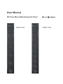
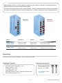
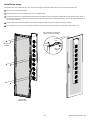
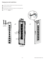
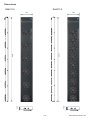
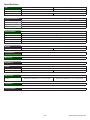
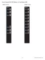
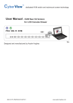
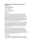
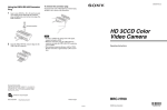
Toll Free: 1-888-865-6888
Tel: 510-226-8368 Fax: 510-226-8968
Email: [email protected]
User Manual
33U Door Mount Monitoring Fan Panel
RA4017-6-M
RA4017-9-M
Legal Information
First English printing, October 2002
Information in this document has been carefully checked for accuracy; however, no guarantee is given to the correctness
of the contents. The information in this document is subject to change without notice. We are not liable for any injury or
loss that results from the use of this equipment.
Safety Instructions
Please read all of these instructions carefully before you use the device. Save this manual for
future reference.
■
■
■
■
■
■
■
■
■
■
■
Unplug equipment before cleaning. Don’t use liquid or spray detergent; use a moist cloth.
Keep equipment away from excessive humidity and heat. Preferably, keep it in an air-conditioned environment with
temperatures not exceeding 40º Celsius (104º Fahrenheit).
When installing, place the equipment on a sturdy, level surface to prevent it from accidentally falling and causing dam
age to other equipment or injury to persons nearby.
When the equipment is in an open position, do not cover, block or in any way obstruct the gap between it and the
power supply. Proper air convection is necessary to keep it from overheating.
Arrange the equipment’s power cord in such a way that others won’t trip or fall over it.
If you are using a power cord that didn’t ship with the equipment, ensure that it is rated for the voltage and current
labeled on the equipment’s electrical ratings label. The voltage rating on the cord should be higher than the one listed
on the equipment’s ratings label.
Observe all precautions and warnings attached to the equipment.
If you don’t intend on using the equipment for a long time, disconnect it from the power outlet to prevent being dam
aged by transient over-voltage.
Keep all liquids away from the equipment to minimize the risk of accidental spillage. Liquid spilled on to the power
supply or on other hardware may cause damage, fire or electrical shock.
Only qualified service personnel should open the chassis. Opening it yourself could damage the equipment and invali
date its warranty.
If any part of the equipment becomes damaged or stops functioning, have it checked by qualified service personnel.
What the warranty does not cover
■
■
■
Any product, on which the serial number has been defaced, modified or removed.
Damage, deterioration or malfunction resulting from:
Accident, misuse, neglect, fire, water, lightning, or other acts of nature, unauthorized product modification, or
failure to follow instructions supplied with the product.
Repair or attempted repair by anyone not authorized by us.
Any damage of the product due to shipment.
Removal or installation of the product.
Causes external to the product, such as electric power fluctuation or failure.
Use of supplies or parts not meeting our specifications.
Normal wear and tear.
Any other causes which does not relate to a product defect.
Removal, installation, and set-up service charges.
□
□
□
□
□
□
□
□
Regulatory Notices Federal Communications Commission (FCC)
This equipment has been tested and found to comply with the limits for a Class B digital device, pursuant to Part 15 of the
FCC rules. These limits are designed to provide reasonable protection against harmful interference in a residential installation.
Any changes or modifications made to this equipment may void the user’s authority to operate this equipment. This
equipment generates, uses, and can radiate radio frequency energy and, if not installed and used in accordance with the
instructions, may cause harmful interference to radio communications.
However, there is no guarantee that interference will not occur in a particular installation. If this equipment does cause
harmful interference to radio or television reception, which can be determined by turning the equipment off and on, the
user is encouraged to try to correct the interference by one or more of the following measures:
■ Re-position or relocate the receiving antenna.
■ Increase the separation between the equipment and receiver.
■ Connect the equipment into an outlet on a circuit different from that to which the receiver is connected.
www.rackmountmart.com
RA4017 -M Door mount Fan Panel is typically installed on the outside of a cabinet’s rear perforated door to
improve extraction of heat from high density cabinet.
The unit can be attached to most 42U or taller cabinets. If aisle is relatively narrow for exterior mounting, the
unit may be installed on the inside of the perforated door. For details, please refer to the model table below :
Front Door
Cool Air In
Rear Door
Hot Air Out
Model
Installation
Airflow
Purpose
RA40 1 7 -6-M-A
RA40 1 7 -9-M-A
Rear door outside
Extract airflow
Exhaust air out from cabinet
Front door inside
Intake airflow
Cool air in from aisle
RA40 1 7 -6-M-B
RA40 1 7 -9-M-B
Front door outside
Intake airflow
Cool air in from aisle
Rear door inside
Extract airflow
Exhaust air out from cabinet
Unpacking
The equipment comes with the standard parts shown on the package contents. Check and make sure they are included and in good
condition. If anything is missing, or damage, contact the supplier immediately.
Package Content
Optional mounting kit
- 33U door mount fan panel x 1 pc
- Temp. sensor x 1 pc
- 6 ft power cord x 1 pc
- User Manual x 1 pc
- Mounting screw x 6 pcs ( attached with the unit )
- Air blocking material x 1 pc
P.1
Hanging bracket kit
Part no. : PT-HFBK
* For installation, please
refer to p.3
www.rackmountmart.com
Caution -
Power off the fans if the door is to be opened for maintenence or service of
items within the cabinet. The fans have finger guards but care must be excerised when working
around spinning fans. Keep hair, fingers and other small objects away from the spinning blades.
P.2
www.rackmountmart.com
Installation steps
The weight of the unit is less than 5kg, so in most cases, holes in perforated cabinet doors can be used to mount the unit.
1 Lift the unit to the desired position.
2 Place attached 6 screws then through the door and tighten them.
3 To eliminate bypass air to maximize heat removal from the cabinet, cut the air blocking material to the size necessary with cutter or
scissors then apply the material to the inside surface of the door with screws or adhesive backing. Ensure all open perforations are
covered by the material.
4 Connect the power cord to the PDU of the cabinet through the cable entry hole on the rear top of the cabinet.
5 If no cable entry on the top, the unit may be installed on the inside but the model need to be changed. Please refer to P.1 .
Use cable clip to hold the
power cord if necessary
Power
cord
Mounting
screws
Cable
clip
ON / OFF
Button
Perforated
Cabinet Door
P.3
www.rackmountmart.com
Hanging bracket installation
1
Install the hanging bracket kit on the rear side of the fan panel.
2
Hang the unit on the door.
3
Place attached 4 screws then through the door and tighten them.
4
Follow steps
3 - 5 on P.3 .
Power
cord
Cable
clip
ON / OFF
Button
Hanging
bracket kit
Mounting
screws
Perforated
Cabinet Door
P.4
www.rackmountmart.com
Dimensions
RA4017-9
RA4017-6
195
195
1466
42.9
42.9
1466
P.5
www.rackmountmart.com
Specifications
Fan
No. of Fans :
RA4017-6
RA4017-9
6
9
Individual Fan CFM :
Unit CFM ( approx. ) :
108 CFM
648 CFM
972 CFM
Temperature Sensor
Temperature Port
1 x temperature sensor port ( sensor bundled )
Measurement Range
0 to 99.9°C
Measurement Accuracy
+/- 1.5%
Temperature Alarm
Yes
Environmental
Operating :
0 to 50°C Degree
Storage :
-5 to 60°C Degree
Relative humidity :
5~90%, non-condensing
Shock :
50G peak acceleration ( 11ms, half-sine wave )
Vibration :
58~100Hz / 0.98G ( 11ms / cycle )
Weight
Net :
4.3 kgs ( 9.5 lbs)
5 kgs ( 11 lbs)
Black
Casing Color :
33U door mount
Mounting :
FCC, CE
Regulatory :
Power
Input :
Consumption :
Auto-sensing, 100V or 240V AC at 50 or 60Hz via IEC type cord
40W
60W
195 x 42.9 x 1466 mm / 7.7 x 1.7 x 57.7 inch
195 x 42.9 x 1466 mm / 7.7 x 1.7 x 57.7 inch
Dimensions
Product :
FCC & CE
Regulatory
Environmental
RoHS2 & REACH compliant
P.6
www.rackmountmart.com
Front Control ON / OFF Button & Fan Status LED
RA4017-9-M
RA4017-6-M
P.7
www.rackmountmart.com
Temperature Sensor
TEMP
Bundled Temp. Sensor
Part no. : EMS-101-2
- Plug & Play
- External sensor with 2M cord
- Low profile design with magnetic base for easy
affixing to the rack cabinet
Optional 4M cord for Temp. Sensor
P.8
www.rackmountmart.com
Temperature Sensor Specification
Temp. Sensor
Part no.
Temperature
Sensitivity
EMS-101-2
Range
0 to 80°C ( 32 to 176°F )
Accuracy
±1°C ( ±2°F)
Resolution
0.1°C ( 0.2°F )
Response Time
Power
Requirement
Housing
5 to 30 sec
Voltage
12VDC, powered by sensor port
Current Consumption
20mA
Power consumption
0.24 Watt
Power on indicator
Green
Chassis & Cover
Plastic
Color
Dark gray
Installation
Connection
Magnetic base for unrestricted installation
T sensor w/ 2m cable ( standard )
T sensor w/ 4m cable ( option )
Cable Length
Cable Specification
4-wired 3.5mm to RJ11
Cable Color
Beige
Operating
0 to 80°C Degree
Storage
-5 to 80°C Degree
Humidity
0~100%, non-condensing
Dimensions
Product
30L x 25W x 18H mm
Weight
Net
Supply includes
1
Temperature Sensor
2
4-wired 3.5mm to RJ11 cable ( 2m, black color )
Environmental
Compatibility
66g
W / WS / Wi / WSi series PDU
RA4017-M / R / IP Series
EM1001 / 1002 Series
FCC & CE certified
Safety Regulatory
Environmental
RoHS2 & REACH compliant
The company reserves the right to modify product specifications without prior notice and assumes no responsibility
for any error which may appear in this publication.
All brand names, logo and registered trademarks are properties of their respective owners.
Copyright 2013 Synergy Global Technology Inc. All rights reserved.
P.9
www.rackmountmart.com