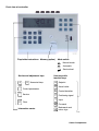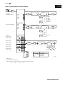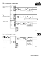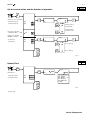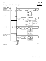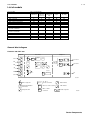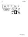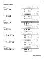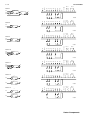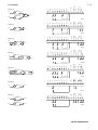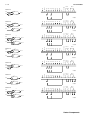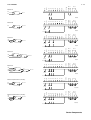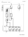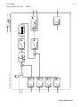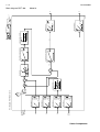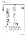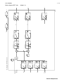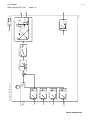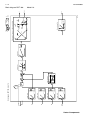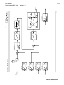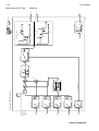
1
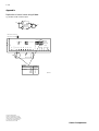
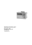
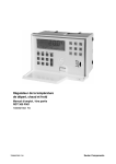
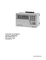
Controller for ventilation
and air-conditioning
User's Manual, part 2
RDT 100 F001 / F002
7000836003 N2
Sauter Components
Front view of controller
Mode switch
Flap holds instructions Memory (option)
Manual mode
Automatic
Service level
Service and adjustment keys
0 ... 9
Numerical keys
PAR
Control parameters
User keys with
function keys
Xs Setpoint
Xi Actual value
XW Control deviation
SERV
Service
Cl Clear
Information centre
Y Positioning signal
I
Input
Forwards
Backwards and
minus sign
B06968
Sauter Components
2-1
List of contents
Service........................................................................................................................................................................................... 3
Choice of model; memory; equipment data; re-start ...................................................................................................................... 4
How to parameterise the data inputs.............................................................................................................................................. 5
How to set the setpoint ranges....................................................................................................................................................... 6
Set the control action and the direction of operation...................................................................................................................... 7
Neutral Zone................................................................................................................................................................................... 7
How to parameterise the control outputs........................................................................................................................................ 8
LCD test and key check ............................................................................................................................................................... 10
Description of parameters ............................................................................................................................................................ 11
bXi. , bXi.
Range Xi for free unit of measurement and active transducer............................................. 11
bY2
Start Y2 ................................................................................................................................ 11
Cod
Code number ....................................................................................................................... 11
cXi.
config Xi............................................................................................................................... 11
cXs.
Calculated setpoint .............................................................................................................. 11
dXi.
Unit of measurement Xi ....................................................................................................... 12
EY1
End Y1 ................................................................................................................................. 12
F1
End of shift ........................................................................................................................... 12
FP
Start of shift.......................................................................................................................... 12
Ini
Initialisation.......................................................................................................................... 12
LME
Load memory....................................................................................................................... 13
LY.
Limit Y.................................................................................................................................. 13
Mod
Model number...................................................................................................................... 13
OF.
Offset ................................................................................................................................... 13
RDT
Type of unit .......................................................................................................................... 13
rXsc
Upper setpoint limit of auxiliary controller ............................................................................ 14
rXsc
Lower setpoint limit of auxiliary controller ............................................................................ 14
rXs
Setpoint range Xs ................................................................................................................ 14
rXs
Setpoint range Xs ................................................................................................................ 14
rY3
Range Y3 output .................................................................................................................. 14
rY3
Range Y3 output .................................................................................................................. 14
SME
Write into memory................................................................................................................ 15
WS
Shift (W) ............................................................................................................................... 15
WS /
Shift (W) ............................................................................................................................... 15
TF.
Time-filter (filter time constant) ............................................................................................ 15
TM
Motor's running time............................................................................................................. 15
Tn.
Integral action time (standardised term) .............................................................................. 15
Ver
Version................................................................................................................................. 16
W. /
Direction of operation: 2-point controller .............................................................................. 16
Xi.
Actual value (standardised term) ......................................................................................... 16
Xm.
Adjustment of measured value Xi ........................................................................................ 16
Xn.
X neutral .............................................................................................................................. 16
Xp.
Proportional band (standardised term) ................................................................................ 16
Xp. /
Control action: controller Xp ................................................................................................ 17
Xs.
Setpoint (standardised term)................................................................................................ 17
Xsd.
Switching difference ............................................................................................................. 17
XsE.
External setpoint .................................................................................................................. 17
Xsh.
Switching range.................................................................................................................... 17
Xw.
Control deviation (standardised term) .................................................................................. 17
Y.
Positioning signal (standardised term)................................................................................. 18
Y0.
Y-0-Point .............................................................................................................................. 18
Y3.
Y3.- source........................................................................................................................... 18
Yc.
Calculated positioning signal ............................................................................................... 18
YM
Ymin-selection / Ymax-selection.......................................................................................... 18
List of models ............................................................................................................................................................................. 19
General block diagram ................................................................................................................................................................. 19
Wiring diagram ............................................................................................................................................................................. 20
Connection diagrams ................................................................................................................................................................... 21
Block diagram RDT 100
Model: 0 ............................................................................................................................... 26
Block diagram RDT 100
Model: 1 ............................................................................................................................... 27
Block diagram RDT 100
Model: 2 ............................................................................................................................... 28
Block diagram RDT 100
Model: 3 ............................................................................................................................... 29
Block diagram RDT 100
Model: 4 ............................................................................................................................... 30
Block diagram RDT 100
Model: 5 ............................................................................................................................... 31
Block diagram RDT 100
Model: 6 ............................................................................................................................... 32
Block diagram RDT 100
Model: 7 ............................................................................................................................... 33
Block diagram RDT 100
Model: 8 ............................................................................................................................... 34
Block diagram RDT 100
Model: 9 ............................................................................................................................... 35
Sauter Components
2-2
Block diagram RDT 100
Model: 10 ..............................................................................................................................36
Block diagram RDT 100
Model: 11 ..............................................................................................................................37
Block diagram RDT 100
Model: 12 ..............................................................................................................................38
Block diagram RDT 100
Model: 13 ..............................................................................................................................39
Block diagram RDT 100
Model: 14 ..............................................................................................................................40
Block diagram RDT 100
Model: 15 ..............................................................................................................................41
Block diagram RDT 100
Model: 16 ..............................................................................................................................42
Block diagram RDT 100
Model: 17 ..............................................................................................................................43
Block diagram RDT 100
Model: 18 ..............................................................................................................................44
Block diagram RDT 100
Model: 20 ..............................................................................................................................45
Block diagram RDT 100
Model: 21 ..............................................................................................................................46
Block diagram RDT 100
Model: 22 ..............................................................................................................................47
Block diagram RDT 100
Model: 23 ..............................................................................................................................48
Block diagram RDT 100
Model: 24 ..............................................................................................................................49
Block diagram RDT 100
Model: 25 ..............................................................................................................................50
Block diagram RDT 100
Model: 26 ..............................................................................................................................51
Block diagram RDT 100
Model: 27 ..............................................................................................................................52
Block diagram RDT 100
Model: 28 ..............................................................................................................................53
Block diagram RDT 100
Model: 29 ..............................................................................................................................54
Block diagram RDT 100
Model: 30 ..............................................................................................................................55
Block diagram RDT 100
Model: 31 ..............................................................................................................................56
Block diagram RDT 100
Model: 32 ..............................................................................................................................57
Block diagram RDT 100
Model: 33 ..............................................................................................................................58
Block diagram RDT 100
Model: 34 ..............................................................................................................................59
Block diagram RDT 100
Model: 35 ..............................................................................................................................60
Diagrams.......................................................................................................................................................................................61
List of parameters .........................................................................................................................................................................62
Appendix .......................................................................................................................................................................................64
Duplication of actual value using Ni1000 ..............................................................................................................................64
Sauter Components
Service
2-3
Service
To gain access to the service level, you have to enter a password (code). It is 6-7-8-9, and
cannot be changed.
Access to the service level can be prevented by sealing the mode switch.
In the service level, the controller is matched to the task in hand by making the following entries, amongst others:− Set the control model
− Configure and adjust the measured-value inputs
− Set the control action and the direction of operation
− Configure the control outputs
All entries and changes should be performed with great care. If a controller fails to work
properly, the cause is often due to incorrect configuration, e.g. the wrong direction of
operation or the wrong type of transmitter.
Sauter Components
2-4
Service
B
E
Choice of model; memory; equipment data; re-start
1)
SERV
2/13/15/16
2-62
Reset to factory setting.
Re-initialise the links.
9
Input
Control -model no. 2)
Memory (option)
- Copies parameters from
memory into controller
Mod
0
Cl
Mod
LME
Cl
OK
Yes
Copies parameters
from memory
into
controller
No 3)
- Copies parameters from
controller into memory
F
SME
Mod
Insert
memory
If not
available
enter model
Cl
Software version
VER
_._
Type of device
R..
---
Re-initialisation
Ini
Cl
Copies parameters
from controller
into
memory
Reset to factory
setting
Re-start
Enter code
B06998
1) Enter code
2) When changeing the control model, always perform 'In' function first!
If entry is invalid, control model 0 used
3) An 'F' in the display stands for 'Fault'. This also appears when there is an internal memory fault after a reset, e.g. due to a power
failure. The controller then uses the default values and control model 0.
Sauter Components
Service
2-5
B
E
How to parameterise the data inputs
2-11/12
2-62
1)
Xi
Input
Data inputs
- Transmitter type 2)
- Unit of measurement
cXi1
1
cXi2
1
cXi3
1
cXi4
2
dXi1
°C
dXi2
°C
dXi3
°C
dXi4
°C
I
I
cXi_
1
2
3
4
5
6
Ni 1000
0...10 V
2...10 V
0...20 mA
4...20 mA
Pot./0...1 V
Input
I
I
dXi_
°C
%
% r.H.
g/kg
kJ/kg
Free unit
Range 3)
- End of range
bXi1
150,0°C
- Start of range
bXi1
-30,0°C
- End of range
bXi2
150,0°C
- Start of range
bXi2
-30,0°C
- End of range
bXi3
150,0°C
- Start of range
bXi3
-30,0°C
-4999...+4999
- End of range
bXi4
150,0°C
- Start of range
bXi4
0°C
Pre-condition:
bXi. > bXi.
4)
Resolution: 2000 steps
free
unit
-
Input
Cl
bXi _ _
3) Unit of meas't
°C and Ni1000
%, % r.H., kJ/kg
g/kg
Fixed range
-30,0...150,0
0,0...100,0
0,0...20,0
B06999a
1) Enter code
2) Insert jumper at rear of unit.
4) Enter: bXi1
= bXi2
and bXi1
= bXi2
for differential controllers.
Sauter Components
2-6
Service
B 2-13/15/16
E
2-62
How to parameterise the data inputs
Adjustment of meas'd value;
unit of measurement is not
displayed
Xm1
----
Xm2
----
Xm3
----
Xm4
----
Input
Cl
Xm_
Measured value
or
Adjustment of meas'd value
by entering offset; unit of
measurement is not shown
- Filter time constant
OF 1
----
OF 2
----
OF 3
----
OF 4
----
TF1
2
TF2
2
TF3
2
TF4
2
Input
Cl
OF_
Value = Meas'd value (Xm.) – Displayed value (Xi.)
Input
Cl
TF_
0...255s
B07000a
B
E
How to set the setpoint ranges
2-14
2-62
1)
Xs
Input
Cl
Limit entries.
Setpoint internal & external
- Maximum value
rXs
150,0°C
- Minimum value
rXs
-30,0°C
rXs_
-30,0...150,0 °C
0,0...100,0 %, % r.H.
0,0...20,0 g/kg
0,0...100,0 kJ/kg
-4999...+4999
For diff. controllers
0,0...150,0 °C
B07001
1) Enter code
Sauter Components
Service
2-7
B
E
Set the control action and the direction of operation
1)
2-15
2-62/63
PAR
6
Input
I
Contr. act.: cont. controllers
- Controller 1 (Pl 1)
Xp1
- Controller 2 (Pl 2)
Xp2
Direction of operation:
command module
(A/B)
Control action A,
works directly
Control action B,
works inversely
Ws
Direction of operation:
ON/OFF controllers (1/2)
- Controller 1
Input
I
W1
- Controller 2
I
Xp_
I
_W_
W2
Dir. of op. A (1)
Dir. of op B (2)
B07002
B
E
Neutral Zone
2-17
2-63
1)
Xw
Input
Cl
Neutral zone
- Controller 1 (Pl 1)
Xn1
0,0°C
- Controller 2 (Pl 2)
Xn2
0,0°C
Xn_
0,0...150,0 °C
0,0...100,0 %, % r.H.
0,0...20,0 g/kg
0,0...100,0 kJ/kg
0...4999
B07003
1) Enter code
Sauter Components
2-8
Service
B 2-14/15/18
E
2-63
How to parameterise the control outputs
1)
Y
Input
I
Starting value
- Positioning signal Y1, 2
Y0
0
I
YO
0
0V
2
2V
Measuring amplifier
- Source Y3
Y3
Xi1
I
- End of range
= 10V
rY3
100,0°C
- Start of range
= 0V
rY3
0,0°C
y
Input
I
3
Xi1...Xi4
Xw1, 2
Yc1, 2
Actual values
Control deviation
Calculated pos. signals
cXi
Differential controller:
cXi = Xi1 - Xi2
Input
Cl
rY3 _
-30,0...150,0°C
0,0...100,0%, %r.H.
0,0...20,0g/kg
0,0...100,0kJ/kg
-4999...+4999
Running time of valve drive
Pre-condition: control model
with 3-pt. output
TM
120
Input
Cl
TM
10...3600s
B07004
1) Enter code
Sauter Components
Service
2-9
B
E
How to parameterise the control outputs
Minimum or Maximum
selection
Pre-condition: model 14
2-9/11/12/18
2-63
Input
YM
I
I
Maximum selection
Minimum selection
Input
Cl
0...100%
Maximum or minimum
limitation
- Pos. signal Y1
LY1
0%
- Pos. signal Y2
LY2
0%
Input
I
I
Maximum limitation
Minimum limitation
Input
Cl
0...100%
Sequence:
- End of left branch (Y1)
EY1
50%
- Start of right branch (Y2)
bY2
50%
Input
I
I
Direction of operation A,
works directly
Direction of operation B,
works inversely
Input
Cl
0...100%
B07005
Sauter Components
2 - 10
Service
LCD test and key check
1)
SERV
9
LCD-Test
Mod
----
Upper
spare key
Upper
spare key
All LCD symbols except left-hand
bar graph are shown
Key check
Lower
spare key
Lower
spare key
Input
Nothing
displayed
Press key; the relevant symbol
appears. N.B.: The plus sign is
shown as
B07006
1) Enter code
Sauter Components
Service
2 - 11
Description of parameters
bXi. , bXi.
Access:
Range Xi for free unit of measurement and active transducer
service level
B
E
2-5
2-62
If the ‘free unit’ is chosen or an active temperature transducer is used, the measuring range must also be stipulated. This is
required, for example, when transducers with an output of 0...20 mA (equivalent to 0...1000 Pa) are used.
bY2
Access:
Start Y2
service level
B
E
2-9
2-63
Direction of operation and starting value of the sequence branch Y2 for dual sequence. End value and direction of operation
can be set. BY2 always ends at 100% Yc. When setting, you should also note the control action of the valves and drives connected. See also EY1.
Cod
Access:
Code number
service level
B
E
2-4
–
To gain access to the service level, a password (code) has to be entered. It is 6-7-8-9 and cannot be changed. Access to the
service level can also be prevented by sealing the mode switch.
cXi.
Access:
config Xi
service level
B
E
2-5
2-62
Settings for the type of sensor connected. In addition, the jumper should be inserted at the rear of the unit.
Possibilities:
Type
1
2
3
cXs.
Calculated setpoint
Access:
service level
Sensor
Ni1000
Voltage 0...10 V
Voltage 2...10 V
Type
4
5
6
Sensor
Current 0...20 mA
Current 4...20 mA
Potentiometer, voltage 0...1 V
B
E
1-11/16
–
Calculated setpoint, e.g. for summer compensation. The setpoint cXs is calculated by the setpoint Xs shifted by the amount
WS. It has an adding or subtracting effect, depending on the configuration.
Sauter Components
2 - 12
Service
dXi.
Access:
Unit of measurement Xi
service level
B
E
2-5
2-62
The actual value's unit of measurement for the display. This stipulation applies simultaneously for all associated parameters,
such as setpoint, proportional band and shift parameters.
Possibilities:
Unit of measurement
°C
g/kg
%
kJ/kg
% r.H. (r.F.)
- (free unit)
N.B.:
If ‘free unit of measurement’ is selected, no unit-of-measurement symbol is shown in manual and automatic modes.
EY1
Access:
End Y1
Service level
B
E
2-9
2-63
Direction of operation and end value of the sequence branch Y1 for dual sequence. Y1 always begins at 0% Yc. End value
and direction of operation can be set. Parameters EY1 and bY2 belong together. When setting, you should also note the control action of the valves and drives connected. See bY2.
F1
Access:
End of shift
Manual
Determines the shift's end point on the command module. See also FP and
FP
Access:
1-21/22
2-62
B
E
1-21/22
2-62
WS.
Start of shift
Manual
Determines the shift's starting point on the command module. See also F1 and
Ini
Access:
B
E
WS.
Initialisation
Service level
B
E
2-4
–
Resets the controller's EEPROM (parameter memory) to the default values. If you change the number of the control model,
you must perform an initialisation beforehand. Default values are shown with a grey background in the operating instructions.
Sauter Components
Service
2 - 13
LME
Access:
Load memory
Service level
B
E
2-4
–
Loads the contents of the external parameter memory (‘memory’) into the controller's internal parameter memory. If any faults
are found, an ‘F’ appears in the display. The memory, which is optional, is not necessary in order to run the controller.
LY.
Access:
Limit Y.
Service level
B
E
2-9
2-63
Value and direction of operation of the Y-limitation. This limitation can be set for positioning signals only, and works only in
automatic mode. The arrow / shows the limitation's direction of operation, while the value shows the minimum or maximum positioning signal as a percentage.
Application: e.g. for setting the minimum fresh-air content.
Mod
Access:
Model number
Service level
B
E
2-4
2-62
The control-model number determines the basic function of the controller, and is the first thing that should be entered when
putting the controller into operation. The entries are two-digit and the preceding nought must be entered as well. If an invalid
model number is entered, a ‘0’ automatically appears. If you change the model number, carry out the ‘Ini’ function.
OF.
Access:
Offset
Service level
B
E
2-6
2-62
Shows the amount of correction due to adjustment of measured value:Example: Measured value 20.0 °C; preferred display (adjustment of measured value) 20.5 °C = offset –0.5.
RDT
Access:
Type of unit
Manual; Service level
B
E
1-21/22
2-4
–
Shows the type of RDT 100.
Sauter Components
2 - 14
Service
Upper setpoint limit of auxiliary controller
rXsc
Access:
Manual
B
E
1-21/22
2-63
Determines (in the case of cascade control) the maximum setpoint of the auxiliary controller. This parameter sets the maximum inlet temperature.
rXsc
Access:
Lower setpoint limit of auxiliary controller
Manual
B
E
1-21/22
2-63
Determines (in the case of cascade control) the minimum setpoint of the auxiliary controller. This parameter sets the minimum
inlet temperature.
rXs
Access:
Setpoint range Xs
Service level
B
E
Sets the maximum input value. The value entered must be greater than or equal to rXs
are set to the same value, no Xs adjustment is possible.
rXs
Access:
and rXs
Setpoint range Xs
Service level
Sets the minimum input value. The value entered must be smaller than or equal to rXs
rY3
Access:
. If the parameters rXs
2-6
2-62
B
E
2-6
2-62
B
E
2-8
2-63
B
E
2-8
2-63
.
Range Y3 output
Service level
Sets the end of the range for the measuring amplifier in the case of a 10-Volt output, e.g. 40 °C.
rY3
Access:
Range Y3 output
Service level
Sets the start of the range for the measuring amplifier in the case of a 0-Volt output, e.g. –20 °C.
If rY3 < rY3 is entered, you can, for instance, configure a P-controller with direction of operation B.
Sauter Components
Service
2 - 15
SME
Access:
Write into memory
Service level
B
E
2-4
–
Writes (copies) the controller's parameters in the external parameter memory.
WS
Access:
Shift (W)
Manual
B
E
1-21/22/23/24
–
Amount of shift. The command module has a shift effect on the active setpoint. In conjunction with the parameters FP and F1
(with preceding mathematical sign), shift is possible in all 4 quadrants. See also FP and F1.
WS /
Access:
Shift (W)
Service level
B
E
2-7
2-62
The command module's direction of operation. The command module has a shift effect on the active setpoint. In conjunction
with the parameters FP and F1 (with preceding mathematical sign), shift is possible in all 4 quadrants.
TF.
Access:
Time-filter (filter time constant)
Service level
B
E
2-15
2-62
Filter time constant for measuring input. The range is 0 (off) to 255 seconds. The filter represents a mathematically approximated delay of the first degree. For fast controlled networks, it is important not to set the filter time constant too large. The
delay causes an additional phase shift in the control loop, which can lead to hunting.
This function is intended, for example, for use in room-pressure control for arresting pressure surges. Do not use for attenuating fluctuating measured values, caused e.g. by disturbance. In this case, the source of the interference itself should be attenuated.
TM
Access:
Motor's running time
Manual
B
E
2-8
2-63
Running time (in seconds) of motorised drive for 100% stroke; is needed only for three-point output and quasi-continuous
control; the pulse duration is matched to the running time.
Tn.
Access:
Integral action time (standardised term)
Service level
B
E
1-21/22/23/24
2-63
When Tn = 0, the I component is switched off; the controller then has purely a P characteristic.
Sauter Components
2 - 16
Service
Ver
Version
Access:
Manual, service level
B
E
1-21/22/23/24
2-4
–
The software version is shown. This is needed when making technical enquiries.
W.
/
Access:
Direction of operation: 2-point controller
Service level
B
E
2-7
2-63
Use
or
to set the direction of operation of the two-point controller.
provides direction of operation 1 (relay cuts in when
actual value rises),
provides direction of operation 2 (relay cuts in when actual value is falling).
Xi.
Access:
Actual value (standardised term)
Manual; Automatic
Xm.
Access:
B
E
1-10/16
–
Adjustment of measured value Xi
Service level
B
E
2-6
2-62
B
E
2-7
2-63
Adjustment of measured value by entering the desired display value.
Xn.
Access:
X neutral
Service level
Sets the neutral zone for the relevant control module. The controller's output is frozen within this zone. If Xw stays within the
amount of (Xn/2), the control deviation is considered to be 0. The function has no influence on the Xw indication.
Xp.
Access:
Proportional band (standardised term)
Manual
B
E
1-21/22/23/24
2-63
Sauter Components
Service
Xp.
2 - 17
/
Access:
Control action: controller Xp
Service level
B
E
Use
or
to set the controller's control action.
(works inversely).
Xs.
Access:
provides control action B
Setpoint (standardised term)
Manual; Automatic
Xsd.
Access:
provides control action A (works directly);
2-7
2-63
B
E
1-11/16
2-63
B
E
1-22/23
2-63
Switching difference
Manual
Switching difference for ON/OFF controllers or two-point output Y2 as part of a positioning sequence in models 15...18. The
range is then restricted.
Direction of
Direction of
operation 1
operation 2
Xsd = ≤ bY2
≥ (100-bY2)
XsE.
Access:
External setpoint
Manual; Automatic
B
E
1-11/16
–
The external setpoint can be set either passively by a potentiometer or by active signals. Becomes active by closing contacts
XsE. It always affects controller 1.
Xsh.
Access:
Switching range
Manual
B
E
1-24
2-63
B
E
1-10/16
–
Switching difference for three-point output. The switching difference amounts to 0.25 × Xsh.
Xw.
Access:
Control deviation (standardised term)
Manual; Automatic
Difference between controlled variable (Xi) and setpoint (Xs).
Sauter Components
2 - 18
Service
Y.
Access:
Positioning signal (standardised term)
Manual; Automatic
B
E
1-12/13/17/18/19/20
–
Controller output; voltage signal 0 or 2...10 V.
Y0.
Access:
Y-0-Point
Service level
B
E
2-8
2-63
B
E
2-8
2-63
Stipulates the starting value for the Y-outputs 1+2, (0 = 0 Volt, 2 = 2 Volt). Output Y3 always works from 0...10 Volt.
Y3.
Access:
Y3.- source
Service level
Output Y3 can be used as a measuring amplifier. This parameter determines the input and is used, e.g., to transmit the actual
value. Parameterised accordingly, a P-controller, for instance, can also be configured as a simple anti-frost system. By assigning Yc, a triple sequence can be formed in conjunction with Y1+2.
Yc.
Access:
Calculated positioning signal
Manual; Automatic
B
E
1-12/13/17/18/19/20
–
Calculated controller output in 0...100%; is converted into a positioning signal of either 0...10 V or 2...10 V. In the case of dual
sequence, the positioning signals Y1 and Y2 are formed from this.
YM
Access:
Ymin-selection / Ymax-selection
Service level
B
E
2-9
2-63
Available only for control model 14. Maximum selection can also be achieved by externally connecting control outputs in parallel. By connecting an EXG100 active potentiometer in parallel with a control output, the minimum fresh-air content, for example, can be set externally.
Sauter Components
List of models
2 - 19
List of models
List of models
Controller's structure
No. of control model
1 output
Sequence:
continuous continuouscontinuous
0
1
2
3
12
–
13
–
14
–
–
–
–
–
–
–
1 fixed-value controller
with command
2 fixed-value controllers
with common actual value
with y = min/max selection
1 controller with command
with common command
common actual value;
one with command
common actual value;
common command
1 cascade controller
with command
1 difference controller
with command
Sequence:
continuous2-pt
15
16
–
–
–
–
–
–
1 output
2-pt
1 output
PI (3-pt)
20
22
21
27
–
23
24
25
30
31
–
–
–
–
–
–
–
–
–
28
–
4
6
8
10
5
7
9
11
17
18
–
–
–
–
29
26
32
33
34
35
General block diagram
Flexotron 300 RDT 100
Input X
xi1
Functions
XS
xi2
int/ext
PI/2Pt
1
Output Y
A/B
or
or
y1, Rel.1
or
or
y2, Rel.2
PI/2Pt
2
xi3
or
yp
Option
xi4
Min
(Max)
y3
Memory
S1
B06964
XS
Enter setpoint
PI/2Pt
P-, PI or
on/off controller
Max. limiter
Setpoint limitation
min+max
A/B
Choose control action
Min. limiter
Min. or max.
selection
Dual sequence
Setpoint shift
Min
(Max)
B06745
Sauter Components
2 - 20
List of models
Wiring diagram
RDT 100
2
1
1
0(2)...10V
Pot. 2000 Ni1000 Ri=100kΩ
19
xi
xi
xi
F002
0...1V, Pot.
X4 X3 X2 X1
24V~
Ni1000
0...10 V
0...20 mA
F001
1)
VDR
X2
X3
X4
Y1
Y2
Y3
11
20
18
16
15
12
13
14
17
1 V, 1 mA
Xs ext
10
X1
Rel. 1
19
4
Rel. 2
1)
5
6
7
Controller 1
0(4)...20mA
Ri = 50Ω
1)
15 11 17
8
xi
yp
xs
0...1V ext
xi1
xi2
xi3
xi4
y1
y2
y3
xi
0%
230V~
Yp
0...1V
Ri=500kΩ
Xs ext.
2
On: Xs=ext.
Off: Xs=int.
Pot.
4
5
6
7
8
19
10
1 2
17
Y
y
24 V~
L
1 2 3
N
M
0%
P-controller only
M
A06368d
Sauter Components
List of models
2 - 21
Xi1
PI
10
X1
X2
X3
X4
Y1
Y2
Y3
11
20
18
16
15
12
13
14
17
1 V, 1 mA
Model: 0
Yp
Xs ext
Connection diagrams
Rel. 1
19
4
5
Rel. 2
6
7
8
y1
xi1
y1
Xi1
y1
PI
10
X1
X2
X3
X4
Y1
Y2
Y3
11
20
18
16
15
12
13
14
y1
y2
17
1 V, 1 mA
Model: 1
Yp
Xs ext
A06541
Rel. 1
19
4
5
Rel. 2
6
7
8
y2
xi1
Xi1
PI
10
X1
X2
X3
X4
Y1
Y2
Y3
11
20
18
16
15
12
13
14
17
1 V, 1 mA
Model: 2
Yp
Xs ext
A06542
Rel. 1
19
4
5
Rel. 2
6
7
8
y1
Xi3
xi1
xi3
y1
Xi1
PI
y1
10
X1
X2
X3
X4
Y1
Y2
Y3
11
20
18
16
15
12
13
14
y1
y2
17
1 V, 1 mA
Model: 3
Yp
Xs ext
A06543
Rel. 1
19
4
5
Rel. 2
6
7
8
y2
Xi3
xi1
xi3
Xi1
PI
PI
Yp
10
X1
X2
X3
X4
Y1
Y2
Y3
11
20
18
16
15
12
13
14
xi1
xi2
17
1 V, 1 mA
Model: 4
Xs ext
A06544
Rel. 1
19
4
5
Rel. 2
6
7
8
y1
Xi2
y1
Xi1
PI
y1
PI
10
X1
X2
X3
X4
Y1
Y2
Y3
11
20
18
16
15
12
13
14
xi1
xi2
y1
y2
17
1 V, 1 mA
Model: 5
Yp
Xs ext
A06545
Rel. 1
19
4
5
Rel. 2
6
7
8
y2
Xi2
Xi1
Xi3
PI
PI
Yp
10
X1
X2
X3
X4
Y1
Y2
Y3
11
20
18
16
15
12
13
14
xi1
xi2
xi3
17
1 V, 1 mA
Model: 6
Xs ext
A06546
Rel. 1
19
4
5
Rel. 2
6
7
8
y1
Xi2
y1
A06547
Sauter Components
Model: 7
Xi1
PI
PI
Xi3
y1
Yp
10
X1
X2
X3
X4
Y1
Y2
Y3
11
20
18
16
15
12
13
14
xi1
xi2
xi3
y1
y2
17
1 V, 1 mA
List of models
Xs ext
2 - 22
Rel. 1
19
4
5
Rel. 2
6
7
8
y2
Xi2
Xi1
PI
10
X1
X2
X3
X4
Y1
Y2
Y3
11
20
18
16
15
12
13
14
xi1
xi2
17
1 V, 1 mA
Model: 8
Yp
Xs ext
A06548
Rel. 1
19
4
5
Rel. 2
6
7
8
y1
Xi2
y1
10
Model: 9
Xi1
y1
PI
Xi2
X1
X2
X3
X4
Y1
Y2
Y3
11
20
18
16
15
12
13
14
xi1
xi2
y1
y2
17
1 V, 1 mA
Yp
Xs ext
A06549
Rel. 1
19
4
5
Rel. 2
6
7
8
y2
10
Model: 10
Xi1
Xi2
PI
X1
X2
X3
X4
Y1
Y2
Y3
11
20
18
16
15
12
13
14
xi1
xi2
xi3
17
1 V, 1 mA
Yp
Xs ext
A06550
Rel. 1
19
4
5
Rel. 2
6
7
8
y1
Xi3
y1
10
Model: 11
Xi1
Xi2
PI
y1
X1
X2
X3
X4
Y1
Y2
Y3
11
20
18
16
15
12
13
14
xi1
xi2
xi3
y1
y2
17
1 V, 1 mA
Yp
Xs ext
A06551
Rel. 1
19
4
5
Rel. 2
6
7
8
y2
Xi3
1
Xi1
PI
y1
Yp
10
X1
X2
X3
X4
Y1
Y2
Y3
11
20
18
16
15
12
13
14
xi1
xi2
y1
y2
17
1 V, 1 mA
Model: 12
Xs ext
A06552
Rel. 1
19
4
5
Rel. 2
6
7
8
2
Xi2
PI
y2
1
Xi1
PI
y1
Yp
10
X1
X2
X3
X4
Y1
Y2
Y3
11
20
18
16
15
12
13
14
y1
y2
17
1 V, 1 mA
Model: 13
Xs ext
A06553
Rel. 1
19
4
5
Rel. 2
6
7
8
2
Xi1
PI
y2
xi1
A06554
Sauter Components
Model: 14
1
Xi1
10
PI
Min
Max
2
Xi2
Yp
X1
X2
X3
X4
Y1
Y2
Y3
11
20
18
16
15
12
13
14
xi1
xi2
17
1 V, 1 mA
2 - 23
Xs ext
List of models
Rel. 1
19
4
5
Rel. 2
6
7
8
y1
PI
y1
10
Model: 15
1
Xi1
y1
PI
X1
X2
X3
X4
Y1
Y2
Y3
11
20
18
16
15
12
13
14
17
1 V, 1 mA
Yp
Xs ext
A06555
Rel. 1
19
4
5
Rel. 2
6
7
8
Rel. 2
xi1
y1
Rel. 2
10
Model: 16
Xi1
PI
y1
X1
X2
X3
X4
Y1
Y2
Y3
11
20
18
16
15
12
13
14
17
1 V, 1 mA
Yp
Xs ext
A06556
Rel. 1
19
4
5
Rel. 2
6
7
8
Rel. 2
Xi3
xi1
xi3
Rel. 2
y1
Xi1
PI
y1
PI
Yp
10
X1
X2
X3
X4
Y1
Y2
Y3
11
20
18
16
15
12
13
14
xi1
xi2
17
1 V, 1 mA
Model: 17
Xs ext
A06557
Rel. 1
19
4
5
Rel. 2
6
7
8
Rel. 2
Xi2
y1
Rel. 2
10
Model: 18
Xi1
PI
PI
Xi3
X1
X2
X3
X4
Y1
Y2
Y3
11
20
18
16
15
12
13
14
xi1
xi2
xi3
17
1 V, 1 mA
Yp
Xs ext
A06558
Rel. 1
19
4
5
Rel. 2
6
7
8
y1
Rel. 2
Xi2
y1
Rel. 2
10
Model: 20
Xi1
2Pt
X1
X2
X3
X4
Y1
Y2
Y3
11
20
18
16
15
12
13
14
17
1 V, 1 mA
Yp
Xs ext
A06559
Rel. 1
19
4
5
Rel. 2
6
7
8
Rel. 1
xi1
Rel. 1
Xi1
1
2Pt
Rel. 1
Yp
10
X1
X2
X3
X4
Y1
Y2
Y3
11
20
18
16
15
12
13
14
xi1
xi2
17
1 V, 1 mA
Model: 21
Xs ext
A06560
Rel. 1
19
4
5
Rel. 2
6
7
8
2
Xi2
2Pt
Rel. 2
Rel. 1
Rel. 2
A06561
Sauter Components
Yp
10
Model: 22
Xi1
2Pt
X1
X2
X3
X4
Y1
Y2
Y3
11
20
18
16
15
12
13
14
17
1 V, 1 mA
List of models
Xs ext
2 - 24
Rel. 1
19
4
5
Rel. 2
6
7
8
Rel. 1
Xi3
xi1
xi3
Rel. 1
1
Xi1
2Pt
Rel. 1
Xi3
Yp
10
X1
X2
X3
X4
Y1
Y2
Y3
11
20
18
16
15
12
13
14
xi1
xi2
xi3
17
1 V, 1 mA
Model: 23
Xs ext
A06562
Rel. 1
19
4
5
Rel. 2
6
7
8
2
Xi2
2Pt
Rel. 2
Rel. 1
Rel. 2
1
2Pt
Xi1
Rel. 1
Yp
10
X1
X2
X3
X4
Y1
Y2
Y3
11
20
18
16
15
12
13
14
xi1
xi2
xi3
17
1 V, 1 mA
Model: 24
Xs ext
A06563
Rel. 1
19
4
5
Rel. 2
6
7
8
Xi3
2
Xi2
2Pt
Rel. 2
Rel. 1
Rel. 2
Xi1
1
2Pt
Rel. 1
Xi3
Yp
10
X1
X2
X3
X4
Y1
Y2
Y3
11
20
18
16
15
12
13
14
17
1 V, 1 mA
Model: 25
Xs ext
A06564
Rel. 1
19
4
5
Rel. 2
6
7
8
2
Xi1
2Pt
xi1
Rel. 2
xi3
Rel. 1
10
Model: 26
Xi1
Xi2
2Pt
X1
X2
X3
X4
Y1
Y2
Y3
11
20
18
16
15
12
13
14
xi1
xi2
xi3
17
1 V, 1 mA
Yp
Xs ext
A06565a
Rel. 1
19
4
5
Rel. 2
6
7
8
Rel. 1
Xi3
Rel. 1
1
Xi1
2Pt
Rel. 1
Yp
10
X1
X2
X3
X4
Y1
Y2
Y3
11
20
18
16
15
12
13
14
17
1 V, 1 mA
Model: 27
Xs ext
A06566
Rel. 1
19
4
5
Rel. 2
6
7
8
2
Xi1
2Pt
xi1
Rel. 2
Rel. 1
Rel. 2
1
Xi1
2Pt
Rel. 1
Xi3
Xi1
2
2Pt
Rel. 2
Yp
10
X1
X2
X3
X4
Y1
Y2
Y3
11
20
18
16
15
12
13
14
xi1
xi3
17
1 V, 1 mA
Model: 28
Xs ext
A06567
Rel. 1
19
4
5
Rel. 1
Rel. 2
6
7
8
Rel. 2
A06568
Sauter Components
Yp
10
Model: 29
Xi1
2Pt
X1
X2
X3
X4
Y1
Y2
Y3
11
20
18
16
15
12
13
14
xi1
xi2
17
1 V, 1 mA
2 - 25
Xs ext
List of models
Rel. 1
19
4
5
Rel. 2
6
7
8
Rel. 1
Xi2
Rel. 1
10
Model: 30
Xi1
PI
X1
X2
X3
X4
Y1
Y2
Y3
11
20
18
16
15
12
13
14
17
1 V, 1 mA
Yp
Xs ext
A06569
Rel. 1
19
4
5
Rel. 2
6
7
8
Rel. 1+2
yp
0...1V
xi1
Rel. 1
Rel. 2
A06570
10
Model: 31
Xi1
PI
X1
X2
X3
X4
Y1
Y2
Y3
11
20
18
16
15
12
13
14
17
1 V, 1 mA
Yp
Xs ext
P-controller only
Rel. 1
19
4
5
Rel. 2
6
7
8
Rel. 1+2
Xi3
yp
0...1V
xi1
xi3
Rel. 1
Rel. 2
A06571
10
Model: 32
Xi1
PI
PI
X1
X2
X3
X4
Y1
Y2
Y3
11
20
18
16
15
12
13
14
xi1
xi2
17
1 V, 1 mA
Yp
Xs ext
P-controller only
Rel. 1
19
4
5
Rel. 2
6
7
8
Rel. 1+2
Xi2
yp
0...1V
Rel. 1
Rel. 2
A06572
10
Model: 33
Xi1
PI
X1
X2
X3
X4
Y1
Y2
Y3
11
20
18
16
15
12
13
14
xi1
xi2
xi3
17
1 V, 1 mA
Yp
Xs ext
P-controller only
Rel. 1
19
4
5
Rel. 2
6
7
8
PI
Xi3
Rel. 1+2
Xi2
yp
0...1V
Rel. 1
Rel. 2
A06573
Xi1
PI
10
X1
X2
X3
X4
Y1
Y2
Y3
11
20
18
16
15
12
13
14
xi1
xi2
1 V, 1 mA
Yp
Model: 34 (Differential controller)
Xs ext
P-controller only
17
19
4
5
6
7
8
Rel. 1+2
Xi2
yp
0...1V
Rel. 1
Rel. 2
A06574a
10
Model: 35 (Differential controller)
Xi1
Xi2
PI
X1
X2
X3
X4
Y1
Y2
Y3
11
20
18
16
15
12
13
14
xi1
xi2
xi3
17
1 V, 1 mA
Yp
Xs ext
P-controller only
Rel. 1
19
4
5
Rel. 2
6
7
8
Rel. 1+2
Xi3
yp
0...1V
Rel. 1
Rel. 2
A06575a
P-controller only
Sauter Components
Xi4
(Xs-external)
Xi3
Xi2
xi
xi
xi
x
xi
Input module 4
x
Input module 3
x
Input module 2
x
Input module 1
dXi4
bXi4
bXi4
cXi4
TF4
(Jumper)
dXi3
bXi3
bXi3
cXi3
TF3
(Jumper)
dXi2
bXi2
bXi2
cXi2
TF2
(Jumper)
dXi1
bXi1
bXi1
cXi1
TF1
(Jumper)
Xw1
Xn1
Xwr
Neutral zone
Xw1
yc1
PI-controller 1
t
Xp1
Tn1
Xp1
yc1
Xi1
0
y
100%
LY
Y0
y
0
rY3
10V
rY3
Xi1...4, Xw.
Yc., cXi
Measuring amplifier
LY.
0
10V
Output module 1
PI
B07046
y1
y3
y1
Block diagram RDT 100
Xi1
ON:
Xs-external
Xs1
Block diagram, RDT 100, model: 0
2 - 26
List of models
Model: 0
Sauter Components
Xi4
(Xs-external)
Xi3
Xi2
xi
xi
xi
x
xi
Input module 4
x
Input module 3
x
Input module 2
x
Input module 1
dXi4
bXi4
bXi4
cXi4
TF4
(Jumper)
dXi3
bXi3
bXi3
cXi3
TF3
(Jumper)
dXi2
bXi2
bXi2
cXi2
TF2
(Jumper)
dXi1
bXi1
bXi1
cXi1
TF1
(Jumper)
Xw1
Xn1
Xwr
Neutral zone
Xw1
yc1
PI-controller 1
t
Xp1
Tn1
Xp1
yc
LY1.
LY2.
0
10V
y1,2
Y2
PI
yc
LY
Y0
y
0
rY3
10V
rY3
Xi1...4, Xw.
Yc., cXi
Measuring amplifier
EY1BY2 100%
Y1
Output module 1, sequence
Xi1
B07047
y2
y1
y3
y2
y1
Block diagram RDT 100
Xi1
ON:
Xs-external
Xs1
Block diagram, RDT 100, model: 1
List of models
2 - 27
Model: 1
Sauter Components
Xi4
(Xs-external)
Xi3
Xi2
xi
xi
xi
x
xi
Input module 4
x
Input module 3
x
Input module 2
x
Input module 1
dXi4
bXi4
bXi4
cXi4
TF4
(Jumper)
dXi3
bXi3
bXi3
cXi3
TF3
(Jumper)
dXi2
bXi2
bXi2
cXi2
TF2
(Jumper)
dXi1
bXi1
bXi1
cXi1
TF1
(Jumper)
∆Ws
FP
∆Xs
Command module
F1
cXs1
xi3
Xw1
Xn1
Xwr
Neutral zone
Xw1
yc1
PI-controller 1
t
Xp1
Tn1
Xp1
yc1
0
y
100%
y
0
rY3
10V
rY3
PI
yc
LY
Y0
Xi1...4, Xw.
Yc., cXi
Measuring amplifier
LY.
0
10V
Output module 1
Xi3
Xi1
B07048
y1
y3
y1
Block diagram RDT 100
Xi1
ON:
Xs-external
Xs1
Block diagram, RDT 100, model: 2
2 - 28
List of models
Model: 2
Sauter Components
Xi4
(Xs-external)
Xi3
Xi2
xi
xi
xi
x
xi
Input module 4
x
Input module 3
x
Input module 2
x
Input module 1
dXi4
bXi4
bXi4
cXi4
TF4
(Jumper)
dXi3
bXi3
bXi3
cXi3
TF3
(Jumper)
dXi2
bXi2
bXi2
cXi2
TF2
(Jumper)
dXi1
bXi1
bXi1
cXi1
TF1
(Jumper)
∆Ws
FP
∆Xs
Command module
F1
cXs1
xi3
Xw1
Xn1
Xwr
Neutral zone 1
Xw1
yc1
PI-controller 1
t
Xp1
Tn1
Xp1
yc1
LY1.
LY2.
0
10V
y1,2
100%
EY1BY2
y
0
rY3
10V
rY3
PI
yc
LY
Y0
Xi1...4, Xw.
Yc., cXi
Measuring amplifier
Y2
Y1
Output module 1, sequence
Xi3
Xi1
B07049
y2
y1
y3
y2
y1
Block diagram RDT 100
Xi1
ON:
Xs-external
Xs1
Block diagram, RDT 100, model: 3
List of models
2 - 29
Model: 3
Sauter Components
Xi4
(Xs-external)
Xi3
Xi2
xi
xi
xi
x
xi
Input module 4
x
Input module 3
x
Input module 2
x
Input module 1
dXi4
bXi4
bXi4
cXi4
TF4
(Jumper)
dXi3
bXi3
bXi3
cXi3
TF3
(Jumper)
dXi2
bXi2
bXi2
cXi2
TF2
(Jumper)
dXi1
bXi1
bXi1
cXi1
TF1
(Jumper)
Xw1
Xn1
Xwr
Neutral zone 1
cXs2
Xw1
Xw2
t
Xp1
Tn1
Xp1
yc2
t
Xp2
Tn2
Xp2
PI-controller 2 (auxiliary controller)
yc1
PI-controller 1 (main controller)
yc1
rXsc
rXsc
yc2
0
cXs
100%
Command, aux. controller
Xi2
0
y
100%
y
0
rY3
10V
rY3
PI
yc
LY
Y0
Xi1...4, Xw.
Yc., cXi
Measuring amplifier
LY.
0
10V
Output module 1
yc
PI
B07050
y1
y3
y1
Block diagram RDT 100
Xi1
ON:
Xs-external
Xs1
Block diagram, RDT 100, model: 4
Xi1
2 - 30
List of models
Model: 4
Sauter Components
Xi4
(Xs-external)
Xi3
Xi2
xi
xi
xi
x
xi
Input module 4
x
Input module 3
x
Input module 2
x
Input module 1
dXi4
bXi4
bXi4
cXi4
TF4
(Jumper)
dXi3
bXi3
bXi3
cXi3
TF3
(Jumper)
dXi2
bXi2
bXi2
cXi2
TF2
(Jumper)
dXi1
bXi1
bXi1
cXi1
TF1
(Jumper)
Xw1
Xn1
Xwr
Neutral zone 1
cXs2
Xw1
Xw2
t
Xp1
Tn1
Xp1
yc2
t
Xp2
Tn2
Xp2
PI-controller 2 (aux. controller)
yc1
PI-controller 1 (main controller)
yc1
yc2
rXsc
rXsc
0
cXs
yc
LY1.
LY2.
0
10V
y1,2
100%
Y2
y
0
rY3
10V
rY3
PI
Xi1...4, Xw.
Yc., cXi
yc
LY
Y0
Measuring amplifier
EY1BY2
Y1
Output module 1, sequence
100%
Command, aux. controller
Xi2
PI
B07051
y2
y1
y3
y2
y1
Block diagram RDT 100
Xi1
ON:
Xs-external
Xs1
Block diagram, RDT 100, model: 5
Xi1
List of models
2 - 31
Model: 5
Sauter Components
Xi4
(Xs-external)
Xi3
Xi2
xi
xi
xi
x
xi
Input module 4
x
Input module 3
x
Input module 2
x
Input module 1
dXi4
bXi4
bXi4
cXi4
TF4
(Jumper)
dXi3
bXi3
bXi3
cXi3
TF3
(Jumper)
dXi2
bXi2
bXi2
cXi2
TF2
(Jumper)
dXi1
bXi1
bXi1
cXi1
TF1
(Jumper)
∆Ws
FP
∆Xs
Command module
F1
cXs1
xi3
Xw1
cXs2
Xn1
Xwr
Neutral zone
Xw2
Xw1
t
Xp1
Tn1
Xp1
yc2
t
Xp2
Tn2
Xp2
PI-controller 2 (aux. controller)
yc1
PI-controller 1 (main controller)
yc1
rXsc
rXsc
yc2
0
cXs
100%
Command, aux. controller
Xi2
0
y
100%
y
0
rY3
10V
rY3
PI
yc
LY
Y0
Xi1...4, Xs.
Yc., cXi
Measuring amplifier
LY.
0
10V
Output module 1
yc
PI
B07052
y1
y3
y1
Block diagram RDT 100
Xi1
ON:
Xs-external
Xs1
Block diagram, RDT 100, model: 6
Xi3
Xi1
2 - 32
List of models
Model: 6
Sauter Components
Xi4
(Xs-external)
Xi3
Xi2
xi
xi
xi
x
xi
Input module 4
x
Input module 3
x
Input module 2
x
Input module 1
dXi4
bXi4
bXi4
cXi4
TF4
(Jumper)
dXi3
bXi3
bXi3
cXi3
TF3
(Jumper)
dXi2
bXi2
bXi2
cXi2
TF2
(Jumper)
dXi1
bXi1
bXi1
cXi1
TF1
(Jumper)
∆Ws
FP
∆Xs
Command module
F1
cXs1
xi3
Xw1
cXs2
Xn1
Xwr
Neutral zone
Xw2
Xw1
t
Xp1
Tn1
Xp1
yc2
t
Xp2
Tn2
Xp2
PI-controller 2 (aux. controller)
yc1
PI-controller 1 (main controller)
yc1
yc2
rXsc
rXsc
0
cXs
yc
LY1.
LY2.
0
10V
y1,2
100%
Y2
y
0
rY3
10V
rY3
PI
Xi1...4, Xs.
Yc., cXi
yc
LY
Y0
Measuring amplifier
EY1BY2
Y1
Output module 1, sequence
100%
Command, aux. controller
Xi2
PI
B07053
y2
y1
y3
y2
y1
Block diagram RDT 100
Xi1
ON:
Xs-external
Xs1
Block diagram, RDT 100, model: 7
Xi3
Xi1
List of models
2 - 33
Model: 7
Sauter Components
Xi4
(Xs-external)
Xi3
Xi2
xi
xi
xi
x
xi
Input module 4
x
Input module 3
x
Input module 2
x
Input module 1
dXi4
bXi4
bXi4
cXi4
TF4
(Jumper)
dXi3
bXi3
bXi3
cXi3
TF3
(Jumper)
dXi2
bXi2
bXi2
cXi2
TF2
(Jumper)
dXi1
bXi1
bXi1
cXi1
TF1
(Jumper)
cXi
Xw1
Xn1
Xwr
Neutral zone 1
Xw1
yc1
PI-controller 1
t
Xp1
Tn1
Xp1
yc
Xi1
0
y
100%
y
0
rY3
10V
rY3
PI
LY
Y0
Xi1...4, Xw.
Yc., cXi
Measuring amplifier
LY.
0
10V
Output module 1
Xi2
B07054
y1
y3
y1
Block diagram RDT 100
Xi1
ON:
Xs-external
Xs1
Block diagram, RDT 100, model: 8
2 - 34
List of models
Model: 8
Sauter Components
Xi4
(Xs-external)
Xi3
Xi2
xi
xi
xi
x
xi
Input module 4
x
Input module 3
x
Input module 2
x
Input module 1
dXi4
bXi4
bXi4
cXi4
TF4
(Jumper)
dXi3
bXi3
bXi3
cXi3
TF3
(Jumper)
dXi2
bXi2
bXi2
cXi2
TF2
(Jumper)
dXi1
bXi1
bXi1
cXi1
TF1
(Jumper)
cXi
Xw1
Xn1
Xwr
Neutral zone 1
Xw1
yc1
PI-controller 1
t
Xp1
Tn1
Xp1
yc
LY1.
LY2.
0
10V
y1,2
100%
EY1BY2
y
0
rY3
10V
rY3
PI
Xi1...4, Xw.
Yc., cXi
yc
LY
Y0
Measuring amplifier
Y2
Y1
Output module 1, sequene
Xi2
Xi1
B07055
y2
y1
y3
y2
y1
Block diagram RDT 100
Xi1
ON:
Xs-external
Xs1
Block diagram, RDT 100, model: 9
List of models
2 - 35
Model: 9
Sauter Components
Xi4
(Xs-external)
Xi3
Xi2
xi
xi
xi
x
xi
Input module 4
x
Input module 3
x
Input module 2
x
Input module 1
dXi4
bXi4
bXi4
cXi4
TF4
(Jumper)
dXi3
bXi3
bXi3
cXi3
TF3
(Jumper)
dXi2
bXi2
bXi2
cXi2
TF2
(Jumper)
dXi1
bXi1
bXi1
cXi1
TF1
(Jumper)
∆Ws
FP
∆Xs
Command module
F1
cXs1
xi3
cXi
Xw1
Xn1
Xwr
Neutral zone 1
Xw1
yc1
PI-controller 1
t
Xp1
Tn1
Xp1
yc
0
y
100%
LY
Y0
y
0
rY3
10V
rY3
Xi1...4, Xw.
Yc., cXi
Measuring amplifier
LY.
0
10V
Output module 1
PI
B07056
y1
y3
y1
Block diagram RDT 100
Xi1
ON:
Xs-external
Xs1
Block diagram, RDT 100, model: 10
Xi2
Xi3
Xi1
2 - 36
List of models
Model: 10
Sauter Components
Xi4
(Xs-external)
Xi3
Xi2
xi
xi
xi
x
xi
Input module 4
x
Input module 3
x
Input module 2
x
Input module 1
dXi4
bXi4
bXi4
cXi4
TF4
(Jumper)
dXi3
bXi3
bXi3
cXi3
TF3
(Jumper)
dXi2
bXi2
bXi2
cXi2
TF2
(Jumper)
dXi1
bXi1
bXi1
cXi1
TF1
(Jumper)
∆Ws
FP
∆Xs
Command module
F1
cXs1
xi3
cXi
Xw1
Xn1
Xwr
Neutral zone 1
Xw1
yc1
PI-controller 1
t
Xp1
Tn1
Xp1
yc
LY1.
LY2.
0
10V
y1,2
100%
EY1BY2
y
0
rY3
10V
rY3
Xi1...4, Xw.
Yc., cXi
yc
LY
Y0
Measuring amplifier
Y2
Y1
Output module 1, sequence
PI
B07057
y2
y1
y3
y2
y1
Block diagram RDT 100
Xi1
ON:
Xs-external
Xs1
Block diagram, RDT 100, model: 11
Xi1
Xi2
Xi3
List of models
2 - 37
Model: 11
Sauter Components
Xi4
(Xs-external)
Xi3
Xi2
xi
xi
xi
x
xi
Input module 4
x
Input module 3
x
Input module 2
x
Input module 1
dXi4
bXi4
bXi4
cXi4
TF4
(Jumper)
dXi3
bXi3
bXi3
cXi3
TF3
(Jumper)
dXi2
bXi2
bXi2
cXi2
TF2
(Jumper)
dXi1
bXi1
bXi1
cXi1
TF1
(Jumper)
Xs2
Xw2
Xw1
Xn2
Xwr
Neutral zone 2
Xn1
Xwr
Neutral zone 1
Xw2
Xw1
yc2
PI-controller 2
yc1
PI-controller 1
t
Xp2
Tn2
Xp2
t
Xp1
Tn1
Xp1
Xi1
PI
yc2
yc1
y1
0
y
100%
0
y
100%
y
0
rY3
10V
rY3
PI
yc2
LY
Y0
yc
LY
Y0
Xi1...4, Xw.
Yc., cXi
Measuring amplifier
LY.
0
10V
Output module 2
LY.
0
10V
Output module 1
Xi2
B07058
y2
y3
y2
y1
Block diagram RDT 100
Xi1
ON:
Xs-external
Xs1
Block diagram, RDT 100, model: 12
2 - 38
List of models
Model: 12
Sauter Components
Xi4
(Xs-external)
Xi3
Xi2
xi
xi
xi
x
xi
Input module 4
x
Input module 3
x
Input module 2
x
Input module 1
dXi4
bXi4
bXi4
cXi4
TF4
(Jumper)
dXi3
bXi3
bXi3
cXi3
TF3
(Jumper)
dXi2
bXi2
bXi2
cXi2
TF2
(Jumper)
dXi1
bXi1
bXi1
cXi1
TF1
(Jumper)
Xs2
Xw2
Xw1
Xn2
Xwr
Neutral zone 2
Xn1
Xwr
Neutral zone 1
Xw2
Xw1
yc2
PI-Controller 2
yc1
PI-Controller 1
t
Xp2
Tn2
Xp2
t
Xp1
Tn1
Xp1
Xi1
PI
yc2
yc1
y1
0
y
100%
0
y
100%
yc2
LY
Y0
yc
LY
Y0
y
0
rY3
10V
rY3
Xi1...4, Xw.
Yc., cXi
Measuring amplifier
LY.
0
10V
Output module 2
LY.
0
10V
Output module 1
PI
B07059
y2
y3
y2
y1
Block diagram RDT 100
Xi1
ON:
Xs-external
Xs1
Block diagram, RDT 100, model: 13
List of models
2 - 39
Model: 13
Sauter Components
Xi4
(Xs-external)
Xi3
Xi2
xi
xi
xi
x
xi
Input module 4
x
Input module 3
x
Input module 2
x
Input module 1
dXi4
bXi4
bXi4
cXi4
TF4
(Jumper)
dXi3
bXi3
bXi3
cXi3
TF3
(Jumper)
dXi2
bXi2
bXi2
cXi2
TF2
(Jumper)
dXi1
bXi1
bXi1
cXi1
TF1
(Jumper)
Xs2
Xw2
Xw1
Xn2
Xwr
Neutral zone 2
Xn1
Xwr
Neutral zone 1
Xw2
Xw1
yc2
PI-controller 2
yc1
PI-controller 1
t
Xp2
Tn2
Xp2
t
Xp1
Tn1
Xp1
yc2
yc1
Min
Max
0
y
100%
yc
LY
Y0
y
0
rY3
10V
rY3
Min
Max
Xi1...4, Xw.
Yc., cXi
Measuring amplifier
LY.
0
10V
Output module 1
PI
PI
B07060
y1
y3
y1
Block diagram RDT 100
Xi1
ON:
Xs-external
Xs1
Block diagram, RDT 100, model: 14
Xi2
Xi1
2 - 40
List of models
Model: 14
Sauter Components
Xi4
(Xs-external)
Xi3
Xi2
xi
xi
xi
x
xi
Input module 4
x
Input module 3
x
Input module 2
x
Input module 1
dXi4
bXi4
bXi4
cXi4
TF4
(Jumper)
dXi3
bXi3
bXi3
cXi3
TF3
(Jumper)
dXi2
bXi2
bXi2
cXi2
TF2
(Jumper)
dXi1
bXi1
bXi1
cXi1
TF1
(Jumper)
Xw1
Xn1
Xwr
Neutral zone 1
Xw1
yc1
PI-controller 1
t
Xp1
Tn1
Xp1
yc1
PI
0
LY1
10V
y1
LY1
Y0
Y1
bY2
y
0
rY3
10V
rY3
Rel. 2
y1
Xi1...4, Xw.
Yc., cXi
B07061
100% yc
Direction 2
ON
indic.:
Xsd
Measuring amplifier
EY1
ON
indicator:
Direction 1
Output module 1, sequence, continuous and switching
Xi1
y3
Rel. 2
y1
Block diagram RDT 100
Xi1
ON:
Xs-external
Xs1
Block diagram, RDT 100, model: 15
List of models
2 - 41
Model: 15
Sauter Components
Xi4
(Xs-external)
Xi3
Xi2
xi
xi
xi
x
xi
Input module 4
x
Input module 3
x
Input module 2
x
Input module 1
dXi4
bXi4
bXi4
cXi4
TF4
(Jumper)
dXi3
bXi3
bXi3
cXi3
TF3
(Jumper)
dXi2
bXi2
bXi2
cXi2
TF2
(Jumper)
dXi1
bXi1
bXi1
cXi1
TF1
(Jumper)
∆Ws
FP
∆Xs
Command module
F1
cXs1
xi3
Xw1
Xn1
Xwr
Neutral zone 1
Xw1
yc1
PI-controller 1
t
Xp1
Tn1
Xp1
yc1
0
LY1
10V
y1
LY1
Y0
Y1
bY2
y
0
rY3
10V
rY3
Rel. 2
y1
Xi1...4, Xw.
Yc., cXi
B07062
100% yc
Direction 2
ON
indic.:
Xsd
Measuring amplifier
EY1
ON
indicator:
Direction 1
Output module 1, sequence, continuous and switching
PI
y3
Rel. 2
y1
Block diagram RDT 100
Xi1
ON:
Xs-external
Xs1
Block diagram, RDT 100, model: 16
Xi3
Xi1
2 - 42
List of models
Model: 16
Sauter Components
Xi4
(Xs-external)
Xi3
Xi2
xi
xi
xi
x
xi
Input module 4
x
Input module 3
x
Input module 2
x
Input module 1
dXi4
bXi4
bXi4
cXi4
TF4
(Jumper)
dXi3
bXi3
bXi3
cXi3
TF3
(Jumper)
dXi2
bXi2
bXi2
cXi2
TF2
(Jumper)
dXi1
bXi1
bXi1
cXi1
TF1
(Jumper)
cXs1
Xw1
cXs2
Xn1
Xwr
Neutral zone 1
Xw1
Xw2
t
Xp1
Tn1
Xp1
yc2
t
Xp2
Tn2
Xp2
PI-controller 2 (aux. controller)
yc1
PI-controller 1 (main controller)
yc2
yc1
0
cXs
100%
yc
PI
2Pt
0
LY1
10V
y1
LY1
Y0
Y1
bY2
y
0
rY3
10V
rY3
Rel. 2
y1
Xi1...4, Xw.
Yc., cXi
B07063
100% yc
Direction 2
ON
indic.:
Xsd
Measuring amplifier
EY1
ON
indicator:
Direction 1
Output module1, sequence, continuous and switching
rXsc
rXsc
Command, auxiliary controller
Xi2
PI
y3
Rel. 2
y1
Block diagram RDT 100
Xi1
ON:
Xs-external
Xs1
Block diagram, RDT 100, model: 17
Xi1
List of models
2 - 43
Model: 17
Sauter Components
Xi4
(Xs-external)
Xi3
Xi2
xi
xi
xi
x
xi
Input module 4
x
Input module 3
x
Input module 2
x
Input module 1
dXi4
bXi4
bXi4
cXi4
TF4
(Jumper)
dXi3
bXi3
bXi3
cXi3
TF3
(Jumper)
dXi2
bXi2
bXi2
cXi2
TF2
(Jumper)
dXi1
bXi1
bXi1
cXi1
TF1
(Jumper)
∆Ws
FP
∆Xs
Command module
F1
cXs1
xi3
Xw1
cXs2
Xn1
Xwr
Neutral zone 1
Xw1
Xw2
t
Xp1
Tn1
Xp1
yc2
t
Xp2
Tn2
Xp2
PI-controller 2 (aux. controller)
yc1
PI-controller 1 (main controller)
yc2
yc1
0
cXs
100%
yc
PI
2Pt
0
LY1
10V
y1
LY1
Y0
Y1
bY2
y
0
rY3
10V
rY3
Rel. 2
y1
Xi1...4, Xw.
Yc., cXi
B07064
100% yc
Direction 2
ON
indic.:
Xsd
Measuring amplifier
EY1
ON
indicator:
Direction 1
Output module 1, sequence, continuous and switching
rXsc
rXsc
Command, auxiliary controller
Xi2
PI
y3
Rel. 2
y1
Block diagram RDT 100
Xi1
ON:
Xs-external
Xs1
Block diagram, RDT 100, model: 18
Xi3
Xi1
2 - 44
List of models
Model: 18
Sauter Components
Xi4
(Xs-external)
Xi3
Xi2
xi
xi
xi
x
xi
Input module 4
x
Input module 3
x
Input module 2
x
Input module 1
dXi4
bXi4
bXi4
cXi4
TF4
(Jumper)
dXi3
bXi3
bXi3
cXi3
TF3
(Jumper)
dXi2
bXi2
bXi2
cXi2
TF2
(Jumper)
dXi1
bXi1
bXi1
cXi1
TF1
(Jumper)
Xw1
Xn1
Xwr
Neutral zone 1
Xw1
y1
ON
indicator:
Direction 1
ON/OFF controller 1
0
(Xs)
Xsd
2Pt
y
0
rY3
10V
rY3
Xi1...4, Xw.
Yc., cXi
Measuring amplifier
Xw
Direction of operation 2
ON
Indicator:
Xi1
B07065
Rel. 1
y3
Rel. 1
Block diagram RDT 100
Xi1
ON:
Xs-external
Xs1
Block diagram, RDT 100, model: 20
List of models
2 - 45
Model: 20
Sauter Components
Xi4
(Xs-external)
Xi3
Xi2
xi
xi
xi
x
xi
Input module 4
x
Input module 3
x
Input module 2
x
Input module 1
dXi4
bXi4
bXi4
cXi4
TF4
(Jumper)
dXi3
bXi3
bXi3
cXi3
TF3
(Jumper)
dXi2
bXi2
bXi2
cXi2
TF2
(Jumper)
dXi1
bXi1
bXi1
cXi1
TF1
(Jumper)
Xs2
Xw2
Xw1
Xn2
Xwr
Neutral zone 2
Xn1
Xwr
Neutral zone 1
Xw2
Xw1
Xi1
Rel. 1
ON
indicator:
Direction 1
y1
ON
indicator:
Direction 1
ON/OFF controller 2
y1
ON/OFF controller 1
2Pt
Xsd
0
(Xs)
Xsd
Xw
y
0
rY3
10V
rY3
Xi1...4, Xw.
Yc., cXi
Measuring amplifier
Xw
Direction of operation 2
ON
indicator:
0
(Xs)
2Pt
Direction of operation 2
ON
indicator:
Xi2
B07066
Rel. 2
y3
Rel. 2
Rel. 1
Block diagram RDT 100
Xi1
ON:
Xs-external
Xs1
Block diagram, RDT 100, model: 21
2 - 46
List of models
Model: 21
Sauter Components
Xi4
(Xs-external)
Xi3
Xi2
xi
xi
xi
x
xi
Input module 4
x
Input module 3
x
Input module 2
x
Input module 1
dXi4
bXi4
bXi4
cXi4
TF4
(Jumper)
dXi3
bXi3
bXi3
cXi3
TF3
(Jumper)
dXi2
bXi2
bXi2
cXi2
TF2
(Jumper)
dXi1
bXi1
bXi1
cXi1
TF1
(Jumper)
∆Ws
FP
∆Xs
Command module
F1
cXs1
xi3
Xw1
Xn1
Xwr
Neutral zone 1
Xw1
y1
ON
indicator:
Direction 1
ON/OFF controller 1
0
(Xs)
Xsd
2Pt
y
0
rY3
10V
rY3
Xi1...4, Xw.
Yc., cXi
Measuring amplifier
Xw
Direction of operation 2
ON
indicator:
Xi3
Xi1
B07067
Rel. 1
y3
Rel. 1
Block diagram RDT 100
Xi1
ON:
Xs-external
Xs1
Block diagram, RDT 100, model: 22
List of models
2 - 47
Model: 22
Sauter Components
Xi4
(Xs-external)
Xi3
Xi2
xi
xi
xi
x
xi
Input module 4
x
Input module 3
x
Input module 2
x
Input module 1
dXi4
bXi4
bXi4
cXi4
TF4
(Jumper)
dXi3
bXi3
bXi3
cXi3
TF3
(Jumper)
dXi2
bXi2
bXi2
cXi2
TF2
(Jumper)
dXi1
bXi1
bXi1
cXi1
TF1
(Jumper)
∆Ws
FP
∆Xs
Command module
F1
cXs1
xi3
Xs2
Xw2
Xw1
Xn2
Xwr
Neutral zone 2
Xn1
Xwr
Neutral zone 1
Xw2
Xw1
Xi3
Rel. 1
ON
indicator:
Direction 1
y1
ON
indicator:
Direction 1
ON/OFF controller 2
y1
ON/OFF controller 1
2Pt
0
(Xs)
Xsd
Xw
y
0
rY3
10V
rY3
Xi1...4, Xw.
Yc., cXi
Measuring amplifier
Xw
Direction of operation 2
ON
indicator:
0
(Xs)
Xsd
2Pt
Direction of operation 2
ON
indicator:
Xi2
B07068
Rel. 2
y3
Rel. 2
Rel. 1
Block diagram RDT 100
Xi1
ON:
Xs-external
Xs1
Block diagram, RDT 100, model: 23
Xi1
2 - 48
List of models
Model: 23
Sauter Components
Xi4
(Xs-external)
Xi3
Xi2
xi
xi
xi
x
xi
Input module 4
x
Input module 3
x
Input module 2
x
Input module 1
dXi4
bXi4
bXi4
cXi4
TF4
(Jumper)
dXi3
bXi3
bXi3
cXi3
TF3
(Jumper)
dXi2
bXi2
bXi2
cXi2
TF2
(Jumper)
dXi1
bXi1
bXi1
cXi1
TF1
(Jumper)
∆Ws
FP
∆Xs
F1
cXs2
Command module
Xs2
cXs1
xi3
Xw2
Xw1
Xn2
Xwr
Neutral zone 2
Xn1
Xwr
Neutral zone 1
Xw2
Xw1
Xi3
Xi1
Rel. 1
ON
indicator:
Direction 1
y1
ON
indicator:
Direction 1
ON/OFF controller 2
y1
ON/OFF controller 1
2Pt
0
(Xs)
Xsd
Xw
y
0
rY3
10V
rY3
Xi1...4, Xw.
Yc., cXi
Measuring amplifier
Xw
Direction of operation 2
ON
indicator:
0
(Xs)
Xsd
2Pt
Direction of operation 2
ON
indicator:
Xi2
B07069
Rel. 2
y3
Rel. 2
Rel. 1
Block diagram RDT 100
Xi1
ON:
Xs-external
Xs1
Block diagram, RDT 100, model: 24
List of models
2 - 49
Model: 24
Sauter Components
Xi4
(Xs-external)
Xi3
Xi2
xi
xi
xi
x
xi
Input module 4
x
Input module 3
x
Input module 2
x
Input module 1
dXi4
bXi4
bXi4
cXi4
TF4
(Jumper)
dXi3
bXi3
bXi3
cXi3
TF3
(Jumper)
dXi2
bXi2
bXi2
cXi2
TF2
(Jumper)
dXi1
bXi1
bXi1
cXi1
TF1
(Jumper)
∆Ws
FP
∆Xs
Command module
Xs2
F1
cXs1
xi3
Xw2
Xw1
Xn2
Xwr
Neutral zone
Xn1
Xwr
Neutral zone
Xw2
Xw1
Xi3
Rel. 1
ON
indicator:
Direction 1
y1
ON
indicator:
Direction 1
ON/OFF controller 2
y1
ON/OFF controller 1
2Pt
Xsd
0
(Xs)
Xw
y
0
rY3
10V
rY3
Xi1...4, Xw.
Yc., cXi
Measuring amplifier
Xw
Direction of operation 2
ON
indicator:
0
(Xs)
Xsd
Direction of operation 2
ON
indicator:
2Pt
B07070
Rel. 2
y3
Rel. 2
Rel. 1
Block diagram RDT 100
Xi1
ON:
Xs-external
Xs1
Block diagram, RDT 100, model: 25
Xi1
2 - 50
List of models
Model: 25
Sauter Components
Xi4
(Xs-external)
Xi3
Xi2
xi
xi
xi
x
xi
Input module 4
x
Input module 3
x
Input module 2
x
Input module 1
dXi4
bXi4
bXi4
cXi4
TF4
(Jumper)
dXi3
bXi3
bXi3
cXi3
TF3
(Jumper)
dXi2
bXi2
bXi2
cXi2
TF2
(Jumper)
dXi1
bXi1
bXi1
cXi1
TF1
(Jumper)
∆Ws
FP
∆Xs
Command module
F1
cXs1
xi3
cXi1
Xw1
Xn1
Xwr
Neutral zone
Xw1
y1
ON
indicator:
Direction 1
ON/OFF controller 1
0
(Xs)
Xsd
y
0
rY3
10V
rY3
Xi1...4, Xw.
Yc., cXi
Measuring amplifier
Xw
Direction of operation 2
ON
indicator:
2Pt
B07071
Rel. 1
y3
Rel. 1
Block diagram RDT 100
Xi1
ON:
Xs-external
Xs1
Block diagram, RDT 100, model: 26
Xi2
Xi3
Xi1
List of models
2 - 51
Model: 26
Sauter Components
Xi4
(Xs-External)
Xi3
Xi2
xi
xi
xi
x
xi
Input module 4
x
Input module 3
x
Input module 2
x
Input module 1
dXi4
bXi4
bXi4
cXi4
TF4
(Jumper)
dXi3
bXi3
bXi3
cXi3
TF3
(Jumper)
dXi2
bXi2
bXi2
cXi2
TF2
(Jumper)
dXi1
bXi1
bXi1
cXi1
TF1
(Jumper)
Xs2
cXs1
Xw2
Xw1
Xn2
Xwr
Neutral zone 2
Xn1
Xwr
Neutral zone 1
Xw2
Xw1
Xi1
Rel. 1
ON
indicator:
Direction 1
y1
ON
indicator:
Direction 1
ON/OFF controller 2
y1
ON/OFF controller 1
2Pt
Xsd
0
(Xs)
Xw
y
0
rY3
10V
rY3
Xi1...4, Xw.
Yc., cXi
Measuring amplifier
Xw
Direction of operation 2
ON
indicator:
0
(Xs)
Xsd
Direction of operation 2
ON
indicator:
2Pt
B07072
Rel. 2
y3
Rel. 2
Rel. 1
Block diagram RDT 100
Xi1
ON:
Xs-external
Xs1
Block diagram, RDT 100, model: 27
2 - 52
List of models
Model: 27
Sauter Components
Xi4
(Xs-external)
Xi3
Xi2
xi
xi
xi
x
xi
Input module 4
x
Input module 3
x
Input module 2
x
Input module 1
dXi4
bXi4
bXi4
cXi4
TF4
(Jumper)
dXi3
bXi3
bXi3
cXi3
TF3
(Jumper)
dXi2
bXi2
bXi2
cXi2
TF2
(Jumper)
dXi1
bXi1
bXi1
cXi1
TF1
(Jumper)
∆Ws
FP
∆Xs
F1
cXs2
Command module
Xs2
cXs1
xi3
Xw2
Xw1
Xn2
Xwr
Neutral zone 2
Xn1
Xwr
Neutral zone 1
Xw2
Xw1
Rel. 1
ON
indicator:
Direction 1
y1
ON
indicator:
Direction 1
ON/OFF controller 2
y1
ON/OFF controller 1
2Pt
0
(Xs)
Xsd
Xw
y
0
rY3
10V
rY3
Xi1...4, Xw.
Yc., cXi
Measuring amplifier
Xw
Direction of operation 2
ON
indicator:
0
(Xs)
Xsd
Direction of operation 2
ON
indicator:
2Pt
B07073
Rel. 2
y3
Rel. 2
Rel. 1
Block diagram RDT 100
Xi1
ON:
Xs-external
Xs1
Block diagram, RDT 100, model: 28
Xi3
Xi1
List of models
2 - 53
Model: 28
Sauter Components
Xi4
(Xs-external)
Xi3
Xi2
xi
xi
xi
x
xi
Input module 4
x
Input module 3
x
Input module 2
x
Input module 1
dXi4
bXi4
bXi4
cXi4
TF4
(Jumper)
dXi3
bXi3
bXi3
cXi3
TF3
(Jumper)
dXi2
bXi2
bXi2
cXi2
TF2
(Jumper)
dXi1
bXi1
bXi1
cXi1
TF1
(Jumper)
cXi1
Xw1
Xn1
Xwr
Neutral zone 1
Xw1
y1
ON
indicator:
Direction 1
ON/OFF controller 1
0
(Xs)
Xsd
y
0
rY3
10V
rY3
Xi1...4, Xw.
Yc., cXi
Measuring amplifier
Xw
Direction of operation 2
ON
indicator:
2Pt
B07074
Rel. 1
y3
Rel. 1
Block diagram RDT 100
Xi1
ON:
Xs-external
Xs1
Block diagram, RDT 100, model: 29
Xi2
Xi1
2 - 54
List of models
Model: 29
Sauter Components
YP
Xi4
(Xs-external)
Xi3
Xi2
xi
xi
xi
x
Feedback
x
s
xi
Input module 4
x
Input module 3
x
Input module 2
x
Input module 1
dXi4
bXi4
bXi4
cXi4
TF4
(Jumper)
dXi3
bXi3
bXi3
cXi3
TF3
(Jumper)
dXi2
bXi2
bXi2
cXi2
TF2
(Jumper)
dXi1
bXi1
bXi1
cXi1
TF1
(Jumper)
P-controller only
Xw1
Xn1
Xwr
Neutral zone
Xw1
yc1
PI-controller 1
t
Xp1
Tn1
Xp1
Tm
Rel. 1
'ON' indicator:
Rel.
'ON' indicator:
Xw
Rel. 2
'ON' indicator:
Xw
y
0
rY3
10V
rY3
Xi1...4, Xs.
Yc., cXi
Measuring amplifier
0
(Xs)
Xsh
PI
Rel. 1
'ON' indicator:
Direction of operation 2
0
(Xs)
Xsh
Direction of operation 1
Xi1
B07075
Close
Open
Rel. 1+2
y3
Rel. 2
Rel. 1
Block diagram RDT 100
Xi1
ON:
Xs-external
Xs1
Block diagram, RDT 100, model: 30
List of models
2 - 55
Model: 30
Sauter Components
YP
Xi4
(Xs-External)
Xi3
Xi2
xi
xi
xi
x
Feedback
x
s
xi
Input module 4
x
Input module 3
x
Input module 2
x
Input module 1
dXi4
bXi4
bXi4
cXi4
TF4
(Jumper)
dXi3
bXi3
bXi3
cXi3
TF3
(Jumper)
dXi2
bXi2
bXi2
cXi2
TF2
(Jumper)
dXi1
bXi1
bXi1
cXi1
TF1
(Jumper)
FP
∆Xs
P-controller only
∆Ws
Command module
F1
cXs1
xi3
Xw1
Xn1
Xwr
Neutral zone
Xw1
yc1
PI-controller 1
t
Xp1
Tn1
Xp1
Tm
Rel. 1
'ON' indicator:
Rel.
'ON' indicator:
Xw
Rel. 2
'ON' indicator:
Xw
y
0
rY3
10V
rY3
Xi1...4, Xs.
Yc., cXi
Measuring amplifier
0
(Xs)
Xsh
PI
Rel. 1
'ON' indicator:
Direction of operation 2
0
(Xs)
Xsh
Direction of operation 1
Xi3
Xi1
B07076
Close
Open
Rel. 1+2
y3
Rel. 2
Rel. 1
Block diagram RDT 100
Xi1
ON:
Xs-external
Xs1
Block diagram, RDT 100, model: 31
2 - 56
List of models
Model: 31
Sauter Components
YP
Xi4
(Xs-external)
Xi3
Xi2
xi
xi
xi
x
Feedback
x
s
xi
Input module 4
x
Input module 3
x
Input module 2
x
Input module 1
dXi4
bXi4
bXi4
cXi4
TF4
(Jumper)
dXi3
bXi3
bXi3
cXi3
TF3
(Jumper)
dXi2
bXi2
bXi2
cXi2
TF2
(Jumper)
dXi1
bXi1
bXi1
cXi1
TF1
(Jumper)
P-controller only
Xw1
cXs2
Xn1
Xwr
Neutral zone
Xw1
t
Xp1
Tn1
Xp1
yc2
t
Xp2
Tn2
Xp2
Tm
PI-controller 2 (aux. controller)
yc1
PI-controller 1 (main controller)
yc1
100%
yc
Rel. 1
'ON' indicator:
Xw
Rel. 2
'ON' indicator:
Xw
y
0
rY3
10V
rY3
Xi1...4, Xs.
Yc., cXi
Measuring amplifier
0
(Xs)
Xsh
PI
Rel. 1
'ON' indicator:
Direction of operation 2
0
(Xs)
Xsh
Direction of operation 1
0
cXs
Rel.
'ON' indicator:
rXsc
rXsc
Command, auxiliary controller
Xi2
PI
B07077
Close
Open
Rel. 1+2
y3
Rel. 2
Rel. 1
Block diagram RDT 100
Xi1
ON:
Xs-external
Xs1
Block diagram, RDT 100, model: 32
Xi1
List of models
2 - 57
Model: 32
Sauter Components
YP
Xi4
(Xs-external)
Xi3
Xi2
xi
xi
xi
x
Feedback
x
s
xi
Input module 4
x
Input module 3
x
Input module 2
x
Input module 1
dXi4
bXi4
bXi4
cXi4
TF4
(Jumper)
dXi3
bXi3
bXi3
cXi3
TF3
(Jumper)
dXi2
bXi2
bXi2
cXi2
TF2
(Jumper)
dXi1
bXi1
bXi1
cXi1
TF1
(Jumper)
FP
∆Xs
P-controller only
∆Ws
Command module
F1
cXs1
xi3
Xw1
cXs2
Xn1
Xwr
Neutral zone
Xw1
Xwr
t
Xp1
Tn1
Xp1
yc2
t
Xp2
Tn2
Xp2
Tm
PI-controller 2 (aux. controller)
yc1
PI-controller 1 (main controller)
yc1
100%
yc
Rel. 1
'ON' indicator:
Xw
Rel. 2
'ON' indicator:
Xw
y
0
rY3
10V
rY3
Xi1...4, Xs.
Yc., cXi
Measuring amplifier
0
(Xs)
Xsh
PI
Rel. 1
'ON' indicator:
Direction of oepration 2
0
(Xs)
Xsh
Direction of operation 1
0
cXs
Rel.
'ON' indicator:
rXsc
rXsc
Command, auxiliary controller
Xi2
PI
B07078
Close
Open
Rel. 1+2
y3
Rel. 2
Rel. 1
Block diagram RDT 100
Xi1
ON:
Xs-external
Xs1
Block diagram, RDT 100, model: 33
Xi3
Xi1
2 - 58
List of models
Model: 33
Sauter Components
YP
Xi4
(Xs-external)
Xi3
Xi2
xi
xi
xi
x
Feedback
x
s
xi
Input module 4
x
Input module 3
x
Input module 2
x
Input module 1
dXi4
bXi4
bXi4
cXi4
TF4
(Jumper)
dXi3
bXi3
bXi3
cXi3
TF3
(Jumper)
dXi2
bXi2
bXi2
cXi2
TF2
(Jumper)
dXi1
bXi1
bXi1
cXi1
TF1
(Jumper)
P-controller only
cXi1
Xw1
Xn1
Xwr
Neutral zone 1
Xw1
yc1
PI-controller 1
t
Xp1
Tn1
Xp1
Tm
Rel. 1
'ON' indicator:
Rel.
'ON' indicator:
Xw
Rel. 2
'ON' indicator:
Xw
y
0
rY3
10V
rY3
Xi1...4, Xs.
Yc., cXi
Measuring amplifier
0
(Xs)
Xsh
PI
Rel. 1
'ON' indicator:
Direction of operation 2
0
(Xs)
Xsh
Direction of operation 1
Xi2
Xi1
B07079
Close
Open
Rel. 1+2
y3
Rel. 2
Rel. 1
Block diagram RDT 100
Xi1
ON:
Xs-external
Xs1
Block diagram, RDT 100, model: 34
List of models
2 - 59
Model: 34
Sauter Components
YP
Xi4
(Xs-External)
Xi3
Xi2
xi
xi
xi
x
Feedback
x
s
xi
Input module 4
x
Input module 3
x
Input module 2
x
Input module 1
dXi4
bXi4
bXi4
cXi4
TF4
(Jumper)
dXi3
bXi3
bXi3
cXi3
TF3
(Jumper)
dXi2
bXi2
bXi2
cXi2
TF2
(Jumper)
dXi1
bXi1
bXi1
cXi1
TF1
(Jumper)
FP
∆Xs
P-controller only
∆Ws
Command module
F1
cXs1
xi3
cXi1
Xw1
Xn1
Xwr
Neutral zone 1
Xw1
yc1
PI-controller 1
t
Xp1
Tn1
Xp1
Tm
Rel. 1
'ON' indicator:
Rel.
'ON' indicator:
Rel. 1
'ON' indicator:
Xw
Rel. 2
'ON' indicator:
Xw
y
0
rY3
10V
rY3
Xi1...4, Xs.
Yc., cXi
Measuring amplifier
0
(Xs)
Xsh
Direction of operation 2
0
(Xs)
Xsh
Direction of operation 1
PI
B07080
Close
Open
Rel. 1+2
y3
Rel. 2
Rel. 1
Block diagram RDT 100
Xi1
ON:
Xs-external
Xs1
Blcok diagram, RDT 100, model: 35
Xi2
Xi3
Xi1
2 - 60
List of models
Model: 35
Sauter Components
List of models
2 - 61
Diagrams
Control action
Direction of operation,
ON/OFF controller
Y.
Cascade controller
ON
cXs
Direction 1
10 V
rXSc
ON
Direction 2
Xp
Aux. controller Xi2
(Xp2, Tn2)
Xp
Xsd
0 (2)
0
Xi
100 %
= Control action A
= Control action B
B01060a
rXSc
0
(Xs)
Xi1
B07095
Main controller
(Xp1, Tn1)
Slope: S =
Command module
Dual sequence
- rXSc
Xp1
Y3
10 V
10 V
(. .)
Direction
∆Ws
.YE
Xs
.YA
Xi3
FP
∆Ws
B07084
Measuring amplifier
Y1, 2
cXs
rXSc
Yc 0 (2)
0 rY3
100 %
(rY3
B07090
0 (2)
F1
EY1 bY2
0
Direction
rY3
(rY3
)
100 %
)
Xi., Xw.,
Yc., cXi
B07091
B07085
Minimum limitation of
positioning signals
in dual sequences
Y.
Y1, 2
Y.
10 V
10 V
10 V
Y1
Y2
LY.
LY2
L.Y.
0 (2)
0 (2)
Yc
Yc 0 (2)
0
100 %
B01061
0
Yc1
Yc.
Yc
100 %
B01062
0
Maximum selection
Y1
Yc2
100 %
B07092
Minimum selection
Y1
Maximum limitation of
positioning signal
Yc1, 2
Yc.
B07093
Y1
Y1
Yc1
Yc2
Yc.
Yc1, 2
Yc.
B07094
Sauter Components
2 - 62
List of parameters
Plant
Project no.
Customer
Drawing no.
Job no.
Memory no.
Signature
Date
Operating levels
H (Manual)
A (Automatic)
S (Service)
B07102
Hardware settings (jumper at rear of unit)
Ni 1000
Input
Xi1
Xi2
Xi3
Xi4
0(4)...20 mA
Measured-value inputs
0(2)...10 V
0...1 V
Pot.-meter
X
X
X
Software/control Model all models
Parameter
VER
Model
Software version
Control model
Level
Operating key
S
S
SERV
SERV
Default
value
New
value
---
Parameter
Level
Operating key
Default
value
rXs ▲
Maximal value Xs
S
Xs
150,0°C
rXs ▼
Minimal value Xs
S
Xs
-30,0°C
New
value
∆Ws
Parameter
Operating key
Default
value
New
value
Level
Operating key
Default
value
Control action ▼ ▲
Start of shift
S
PAR
FP
H
PAR
-30,0°C
F1
End of shift
H
PAR
150,0°C
∆Ws
Amount of shift
H
PAR
0,0°C
▲
cXi1
dXi1
Type of transmitter
Unit of measurement
S
S
Xi
Xi
°C
1
bXi1 ▲
End of range
S
Xi
150,0°C
bXi1 ▼
Xm1
OF1
TF1
Start of range
S
Xi
-30,0°C
Adjustment
Offset value
Filter time constant
S
S
S
Xi
Xi
Xi
--2s
cXi2
dXi2
Type of transmitter
Unit of measurement
S
S
Xi
Xi
°C
bXi2 ▲
End of range
S
Xi
150,0°C
bXi2 ▼
Xm2
OF2
TF2
Start of range
S
Xi
-30,0°C
Adjustment
Offset value
Filter time constant
S
S
S
Xi
Xi
Xi
--2s
cXi3
dXi3
Type of transmitter
Unit of measurement
S
S
Xi
Xi
1
°C
bXi3 ▲
End of range
S
Xi
150,0°C
bXi3 ▼
Xm3
OF3
TF3
Start of range
S
Xi
-30,0°C
Adjustment
Offset value
Filter time constant
S
S
S
Xi
Xi
Xi
--2s
cXi4
dXi4
Type of transmitter
Unit of measurement
S
S
Xi
Xi
°C
bXi4 ▲
End of range
S
Xi
150,0°C
bXi4 ▼
Xm4
OF4
TF4
Start of range
S
Xi
-30,0°C
Adjustment
Offset value
Filter time constant
S
S
S
Xi
Xi
Xi
--2s
1
Input Xi3
Command module on the models:
2, 3, 6, 7, 10, 11, 16, 18, 22, 23, 24, 25, 26, 28, 31, 33, 35
Code
Level
Input Xi2
0
Setpoint range (applies for all setpoints)
Code
Parameter
Input Xi1
X
Code
Code
New
value
Input Xi4
2
Sauter Components
2 - 63
Controller
Code
Parameter
Controller (continued)
Level
Operating key
Default
value
New
value
Code
Parameter
Level
Operating key
Controller 1
as an auxiliary controller with cascade and 3-point output
as a continuous controller
for the models: 31, 33
Xp2
for the models: 0...18, 31, 33
Xn1
Neutral zone
S
Xw
0,0°C
Xp1
Control action Xp1 ▲ ▼
Setpoint 1
S
PAR
▼
Xs1
H
Xs
Xp1
Proportional band
H
PAR
Tn1
Integral action time
H
PAR
20,0°C
10,0°C
0s
as an ON/OFF controller
Default
value
Control action Xp2 ▲ ▼
Running time of drive
Upper setpoint limit
S
PAR
S
H
Y
PAR
rXSc▼
Xp2
Lower setpoint limit
H
PAR
18,0°C
Proportional band
H
PAR
Tn2
Xsh
Integral action time
Switching range
H
H
PAR
PAR
10,0°C
0s
Level
S
Operating key
Y
S
Y
▼
0%
S
Y
▼
0%
S
S
Y
Y
150,0°C
S
Y
-30,0°C
S
Y
▼
50%
S
Y
▲
50%
S
Y
▼
50%
S
Y
▲
50%
S
Y
▼
Tm
rXSc▲
New
value
▼
120s
28,0°C
2,0°C
for the models: 20...29
Xn1
Neutral zone
S
Xw
W1
Dir. of operation ▲ ▼
Setpoint 1
S
PAR
▼
Xs1
H
Xs
20,0°C
Xsd1
Switching difference
H
PAR
2,0°C
0,0°C
as a 3-point controller
Positioning signals all models
Code
Parameter
Y0
Starting value Y1 + Y2
Default
value
0
New
value
Positioning signals Y1
for the models: 30, 31, 34, 35
LY1
Limitation ▼ ▲
Limitation value
Xn1
Neutral zone
S
Xw
0,0°C
Xp1
Dir. of operation Xp1 ▲ ▼
Running time of drive
Setpoint 1
S
PAR
Tm
Xs1
S
H
Y
Xs
▼
120s
Positioning signals Y2
20,0°C
LY2
Xp1
Proportional band
H
PAR
Tn1
Xsh
Integral action time
Switching range
H
H
PAR
PAR
10,0°C
0s
Limitation ▼ ▲
Limitation value
Controller 2
Output variable Y3 all models
Y3
Assigned to
End of range
rY3 ▲
as a continuous controller
rY3 ▼
2,0°C
Start of range
Xi3
for the models: 12, 13, 14, 25
Xn2
Neutral zone
S
Xw
0,0°C
Xp2
S
PAR
▼
Xs2
Control action Xp2 ▲ ▼
Setpoint 2
H
Xs
20,0°C
Xp2
Proportional band
H
PAR
Tn2
Integral action time
H
PAR
10,0°C
0s
Dual sequence, continuous
for the models: 3, 5, 7, 9, 11
EY1
Control action Y1 ▼ ▲
End of left-hd. branch Y1
bY2
Control action Y2 ▼ ▲
Start of right-hd. branch Y2
as an ON/OFF controller
for the models: 21, 23, 24, 27, 28
Dual sequence, continuous + switching
Xn2
Neutral zone
S
Xw
0,0°C
W2
S
PAR
▼
Xs2
Dir. of operation ▲ ▼
Setpoint 2
H
Xs
20,0°C
Xsd2
Switching difference
H
PAR
2,0°C
as an auxiliary controller with cascade and continuous output
for the models: 4, 5, 6, 7, 17, 18
Xp2
Control action Xp2 ▲ ▼
Upper setpoint limit
S
PAR
▼
H
PAR
28,0°C
rXSc▼
Xp2
Lower setpoint limit
H
PAR
18,0°C
Proportional band
H
PAR
Tn2
Integral action time
H
PAR
10,0°C
0s
rXSc▲
for the models: 15, 16, 17, 18
EY1
Control action Y1 ▼ ▲
End of left-hd. branch Y1
bY2
Dir. oper. Rel. 2 ▼ ▲
switching point
Choice of control signal
for the model: 14
Choice: MIN/MAX
YM
Sauter Components
2 - 64
Appendix
Duplication of actual value using Ni1000
e.g. model 14 with common input
1
PI
Xi1
Min
Max
2
y1
PI
RDT 100 F001=230 V
RDT 100 F002=24 V
X4 X3 X2 X1
2
1)
Ni1000
0...10 V
0...20 mA
0...1 V, Pot.
VDR
10
X1
X2
X3
X4
Y1
Y2
Y3
11
20
18
16
15
12
13
14
17
1 V, 1 mA
Yp
Xs ext
1
Rel. 1
19
4
Rel. 2
1)
5
1)
6
7
8
xi1 xi2
Ni1000
y1
Settings
Jumper
Parameter
X1 Ni1000
0...1 V
X2
1
cXi1
1
cXi2
°C
dXi1
°C
dXi2
B07122a
Printed in Switzerland
Right of amendment reserved
N.B.: A comma between cardinal
numbers denotes a decimal point
Fr. Sauter AG, CH-4016 Basle
RDT 100 F001 / F002 N2
Sauter Components