1
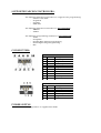
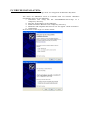
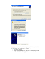
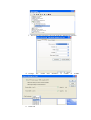
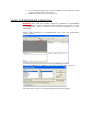
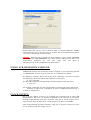
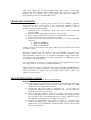
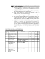
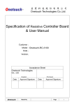
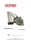
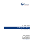
AVR-ISP500 Users Manual All boards produced by Olimex are ROHS compliant Rev.C, May 2009 Copyright(c) 2008, OLIMEX Ltd, All rights reserved INTRODUCTION: AVR-ISP500 is USB low cost in-system programmer for AVR microcontrollers. It implements the STK500v2 protocol as defined by Atmel which makes it compatible with a range of tools, including AvrStudio and avrdude. There are two ways you can use AVR-ISP500 FEATURES: - Fully STK500v2 compatible; Works with AvrStudio, WinAVR, Avrdude and every other software compatible with STK500v2; USB port for connection to PC; One bi-color LED for current operation status; Supports both standard Atmel ICSP10 and ICSP6 layout connectors; Powered by USB; External clock output on ICSP10 pin 3 for rescuing AVRs with enabled external clock fuse; Supports target voltages ranging from 1.8V to 5.5V. ISP clock frequencies ranging from 5kHz to 2MHz. ELECTROSTATIC WARNING: The AVR-ISP500 must not be subject to high electrostatic potentials. General practice for working with static sensitive devices should be applied when working with this board. REQUIREMENTS: Cables: 1.8 meter USB A-B cable (not supplied with the programmer) Software: - AvrStudio, available from Atmel. - avrdude, included in the WinAVR distribution. - Any other software with support for the STK500v2 protocol. SUPPORTED MICROCONTROLLERS: The following AVR microcontrollers are supported for programming: - Classic 8-bit AVRs - megaAVR - tinyAVR - USB AVR The following AVR microcontrollers are not supported: - XMEGA - AVR32 The following programming methods are not supported: - JTAG - debugWire - Parallel High Voltage Programming - Serial High Voltage Programming - PDI CONNECTORS: pin 1 2 3 4 5 6 7 8 9 10 Abbrev. MOSI V_TAR CLKO GND TRST GND SCK GND MISO GND ICSP10 description Serial Output Target VCC Clock output Ground Target RESET Ground Serial Clock Ground Serial Input Ground pin 1 2 3 4 5 6 Abbrev. MISO V_TAR SCK MOSI TRST GND ICSP6 description Serial Input Target VCC Serial Clock Serial Output Target RESET Ground POWER SUPPLY: The programmer is supplied from USB. PC DRIVER INSTALLATION: Drivers for the Mass Storage mode are integrated in Windows XP/Vista. The driver for STK500v2 mode is available from our website. Windows installation steps are the following: 1. Download and unzip the file “AVR-STK500-drivers.zip” in a temporary directory. 2. Plug the programmer in the USB port. 3. Point the Device Wizard to the temporary directory. 4. Windows will complain that drivers are not signed. Click “Continue”. 5. Click finish. Screen shots of the steps are shown below: WARNING: The COM port number assigned by Windows to AVR-ISP500 must be COM4 or below. Otherwise AvrStudio might not be able to detect the programmer. Here are the steps to change it: 1. Go to Device Manager. 2. Unfold “Ports (COM&LPT)” and right-click on “Olimex Virtual COM AVR-ISP500 (COMxx)” where COMxx can be anything between COM1 and COM255. Select properties. 3. Go to the “Port Settings” tab and click the “Advanced” button. 4. Change 5. Click OK. the “COM Port Number” to COM3 or COM4. 6. If a warning message pops up and complains about COM port being used by another device, click “Yes”. 7. Click OK to close the device properties. USING AVR-ISP500 WITH AVRSTUDIO: WARNING: The COM port number assigned by Windows to AVR-ISP500 must be COM4 or below. Otherwise AvrStudio might not be able to detect the programmer. See the section for PC Drivers Installation for more information. Usage under AvrStudio is straightforward. First open the Programmer Connect dialog: Then select “STK500 or AVRISP option” with automatic port detection: After pressing “Connect” the programming dialog should appear: Target AVR now can be erased, flashed with a provided HEX file, FUSES and LOCK bits can be written and/or verified. For more information please consult the AvrStudio documentation. CAVEAT: Although the programmer will happily accept setting VTARGET and ARef in the “HW SETTINGS” tab, these actions will have no effect. The programmer hardware can only read target VCC and show it simultaneously in the VTARGET and ARef sliders. USING AVR-ISP500 WITH AVRDUDE: AVRDUDE requires the serial port name, assigned by the Operating System to AVR-ISP500. It must be given with the -P command line option. For Windows systems please check the Device Manager. For Linux systems the following command will list all USB CDC serial ports: ls /dev/ttyACM* For MacOS X systems the following command will list all serial ports: ls /dev/cu.* An example command line for programming an Atmega88 under MacOS X: avrdude -p m88 -B 50 -c stk500v2 -P /dev/cu.usbmodem000010471 -e -U flash:w:blinkled.hex CLOCK OUTPUT: Pin 3 of the ICSP10 connector is normally left unconnected by other ISP programmers. Not ours. In normal programmer state this pin is tri-stated. During programming operation, however, this pin is made output and a square-wave clock is generated. Clock frequency is fixed to 62.5kHz. After programming operation finishes, this pin is again tri-stated in order not to interfere with the target circuit. This clock output can be really helpful when target AVR is accidentally programmed with External Clock FUSE option. To resurrect it just wire ICSP10 pin 3 to XTAL1 pin of the target AVR chip and initiate a programming session to fix the FUSE values. FIRMWARE UPGRADE: AVR-ISP500 contains a built-in boot loader for easy firmware upgrade. Device enters boot loader mode if the application FLASH section is corrupted. To force the device to enter boot loader mode for manual firmware update do the following: 1. Disconnect the programmer from any power source (external AC/DC, USB). 2. Disconnect the programmer from any target boards. 3. Put a jumper between pin 1 and pin 3 of the ICSP10 connector. 4. Power up the device by connecting it to USB. 5. Device now must be in boot loader mode, indicated by the LED light sequence: a. RED off, GREEN on. b. RED on, GREEN off. c. RED off, GREEN off. Jumper can now be removed. The device will stay in boot loader mode until it is power cycled. Boot loader implements the standard protocol XMODEM with CRC16 for firmware update. User is free to use his favorite terminal client (HyperTerminal, minicom, etc) to upload the firmware images taken from our website. The AVR-ISP500 boot loader implements a USB virtual serial port that is baud rate agnostic. As an alternative we provide a simple Windows GUI application for users who don’t want to or cannot use terminal software. After the firmware image is uploaded the target will blink the GREEN LED if update was successful, otherwise it will blink the RED LED if firmware image was invalid or update was unsuccessful. Device stays in this state until it is power cycled. TROUBLESHOOTING GUIDE: Problem: AVR Studio cannot find my programmer. Probable causes and solutions: Look whether the programmer is listed in Device Manager under the “Ports (COM & LPT)” section. If it's not there then check your USB cables and hubs. Reinstall the driver. Check that the green LED is constantly on. If not then the programmer might be in firmware upgrade mode. Go to the firmware upgrade section for more details. Your serial port number might be too high. Check the manual section “Installing drivers” for more information on assigning serial port numbers. Also go to AVR Studio menu “Tools->Options” and set the “Number of COM ports to try” field to at least 20. Remove all applications that might be using or scanning your computer's serial ports, including any serial port monitors. They might mess up the STK500v2 communication between AVR Studio and the programmer. Problem: Programming fails. Target AVR chip cannot enter programming mode. Probable causes and solutions: ISP frequency might be too high. Set the ISP frequency to well below ¼ of target MCU clock. Please note that the AVR MCU clock depends on its fuses configuration. Target power might not be stable enough or supply voltage might be too low. Check your target board circuit. Ensure that the used AVR chip specifications match your supply voltage. Target power supply VCC might not be connected to pin 2 of ICSP6/10. Check your target board circuit. The target AVR MCU might have fuses programmed for disabling SPI ISP or selecting another programming method. In such case you'll need a High Voltage Parallel programmer to unlock the chip. The reset line cannot be pulled low by the programmer. Check your schematic and ensure that only a weak pull-up (and possibly a small capacitor) are connected to RESET. Otherwise, if the pull-up is too small or there is another output driving RESET, the programmer won't be able to pull it down. Another circuit is driving the ISP lines (MISO, MOSI, SCK or RESET) resulting in a contention with the programmer. The solution is to remove all such circuits (LEDs, RS232 drivers, resistors below 2k, etc) from the four ISP lines during programming. AVR-ISP500 is more susceptible to this kind of fault than other programmers on the market because it has 560 ohm resistors in series with all its outputs. This protects both the target MCU and the target board circuit. ELECTRICAL CHARACTERISTICS: Symb ol Description Condition Min VTARG Target Supply Voltage. 1.8 FISP ISP Frequency on SCK SPI pin. 5 VCC Programmer Power Supply Voltage. ICC Programmer Power Supply Current. Typ Max Uni ts 5.5 V 2000 kHz 4.6 5.4 V Idle 25 mA Programming with AvrStudio, VTARG=1.8V, FISP=2MHz 30 mA Time for a full Programming with AvrStudio, programming and VTARG=5V, FISP=2MHz verification of ATmega128 (128k FLASH + 4k EEPROM + FUSES + LOCK + Signature check) 60 s Time for a FLASH programming and verification of ATmega128 (128k FLASH) 25 s Programming with AvrStudio, VTARG=5V, FISP=2MHz ORDER CODE: AVR-ISP500 – assembled and tested (no kit, no soldering required) How to order? You can order to us directly or by any of our distributors. Check our web www.olimex.com/dev for more info. Revision history: REV.A - create April 2008 REV.B - modify January 2009 Added a troubleshooting guide REV.C - modify May 2009 Added instructions for avrdude Disclaimer: © 2008 Olimex Ltd. All rights reserved. Olimex®, logo and combinations thereof, are registered trademarks of Olimex Ltd. Other terms and product names may be trademarks of others. The information in this document is provided in connection with Olimex products. No license, express or implied or otherwise, to any intellectual property right is granted by this document or in connection with the sale of Olimex products. Neither the whole nor any part of the information contained in or the product described in this document may be adapted or reproduced in any material from except with the prior written permission of the copyright holder. The product described in this document is subject to continuous development and improvements. All particulars of the product and its use contained in this document are given by OLIMEX in good faith. However all warranties implied or expressed including but not limited to implied warranties of merchantability or fitness for purpose are excluded. This document is intended only to assist the reader in the use of the product. OLIMEX Ltd. shall not be liable for any loss or damage arising from the use of any information in this document or any error or omission in such information or any incorrect use of the product.