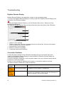
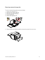
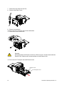
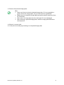
1
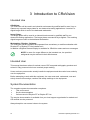
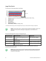
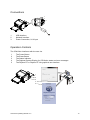
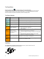
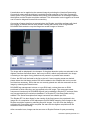
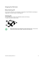
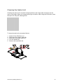
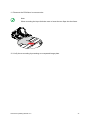
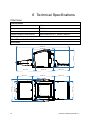
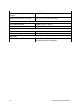
GE Measurement & Control Technologies Computed Radiography CRxVision CRxVision Operating Manual V1.2 LL ID 42124462 Table of Contents 2 CRxVision Operating Manual V1.2 1 Revision History................................................................................................5 2 Introduction to this Manual ..............................................................................7 Scope..............................................................................................................................8 Warning, Cautions, Instructions and Notes.....................................................................8 Disclaimer .......................................................................................................................9 Technical Support ...........................................................................................................9 3 Introduction to CRxVision ..............................................................................10 Intended Use.................................................................................................................10 Intended User ...............................................................................................................10 System Documentation .................................................................................................10 Configuration.................................................................................................................11 Image Plate Details .....................................................................................................................................12 Connections ..................................................................................................................13 Operation Controls ........................................................................................................13 The Erase Button ........................................................................................................................................14 The Status Indicator ....................................................................................................................................14 Ventilation ...................................................................................................................................................14 Compatibility .................................................................................................................15 Compliance ...................................................................................................................15 General .......................................................................................................................................................15 Safety ..........................................................................................................................................................15 Laser Safety ................................................................................................................................................15 Electromagnetic Compatibility .....................................................................................................................15 Environmental Compliance .........................................................................................................................16 Equipment Classification .............................................................................................................................16 Connectivity ..................................................................................................................16 Training .........................................................................................................................16 Installation.....................................................................................................................17 Labels ...........................................................................................................................20 Safety Instructions for Laser Products ..........................................................................21 Cleaning of the CRxVision ............................................................................................21 Cleaning of Image Plates ..............................................................................................22 Preventive Maintenance ...............................................................................................22 Quality Control ..............................................................................................................22 Environmental Protection ..............................................................................................23 Safety Directions ...........................................................................................................24 General safety instructions..........................................................................................................................25 4 Getting started with the CRxVision ...............................................................26 Starting the Digitizer Remote Display ...........................................................................27 Starting Rhythm RT ......................................................................................................27 Starting the CRxVision ..................................................................................................28 Scanning an Image .......................................................................................................29 Stopping the CRxVision ................................................................................................31 Before Switching Off....................................................................................................................................31 Switching Off ...............................................................................................................................................31 CRxVision Operating Manual V1.2 3 5 Operating the CRxVision ................................................................................32 Scanning multiple Image Plates....................................................................................33 Re-erasing an Image Plate ...........................................................................................34 Cleaning the Optics Unit ...............................................................................................35 Troubleshooting ............................................................................................................38 Digitizer Remote Display .............................................................................................................................38 Connection Problems ..................................................................................................................................38 Removing a jammed image plate ................................................................................................................39 6 Technical Specifications ................................................................................42 CRxVision .....................................................................................................................42 Image Plates .................................................................................................................45 4 CRxVision Operating Manual V1.2 1 Revision History CRxVision Operating Manual V1.2 5 Version Date Changes 1.0 2013-10-18 Initial version 1.1 2013-10-30 Changes after certification 1.2 2013-11-07 Adaptations due to new screw type for user accessible parts 6 CRxVision Operating Manual V1.2 2 Introduction to this Manual CRxVision Operating Manual V1.2 7 Scope This manual contains information for safe and effective operation of the CRxVision digitizer system. It describes the basic operation with Rhythm RT. For more details on Rhythm RT or Rhythm RT Lite consult the online manual of the respective application. Warning, Cautions, Instructions and Notes The following samples show how warnings, cautions, instructions and notes appear in this document. The text explains their intended use. WARNING: Warnings are directions which, if they are not followed, can cause fatal or serious injuries to a user, engineer, or any other person or can lead to a wrong inspection result. The purpose of safety icons is to indicate at a glance the type of caution, warning or danger. Hot Surface Obstacles Laser Beam Corrosive Liquid Magnetic Field Ionizing Radiation High Voltage Explosive Material Caution: Cautions are directions which, if they are not followed, can cause damage to the equipment described in this manual or any other equipment or goods and can cause environmental pollution. INSTRUCTION: This sign typically is used in combination with the warning sign, when providing a specific instruction, which if followed exactly, should avoid the subject of the warning. NOTE: Notes provide advice and highlight unusual points. A note is not intended as an instruction. 8 CRxVision Operating Manual V1.2 Disclaimer GE Measurement & Control Technologies assumes no liability for use of this document if any unauthorized changes have been made to the content or format. Every care has been taken to ensure the accuracy of the information in this document. However, GE assumes no responsibility or liability for errors, inaccuracies or omissions that may appear in this document. To improve reliability, function or design GE reserves the right to change the product without further notice. This manual is provided without warranty of any kind, implied or expressed, including, but not limited to, the implied warranties of merchantability and fitness for a particular purpose. Technical Support For technical support contact your dealer, a local customer support center as listed on http://www.ge-mcs.com or GE Sensing & Inspection Technologies GmbH Bogenstrasse 41 22926 Ahrensburg CRxVision Operating Manual V1.2 9 3 Introduction to CRxVision Intended Use CRxVision: The CRxVision will be used in an industrial environment by qualified staff to scan X-ray or Gamma-ray exposed image plates for non destructive testing applications. It results in a digital image which is sent to the dedicated workstation. Image Plates: The image plates will be used in an industrial environment by qualified staff for non destructive testing applications. The image plates are scanned by a digitizer. The resulting digital images are sent to the dedicated workstation. Workstation / Rhythm - Software: The CRxVision will be controlled and operated from a stationary or mobile workstation with Rhythm RT or Rhythm RT Lite installed on it. In addition a Digitizer Remote Display is available for CRxVision status and error messages. NOTE: In case of a usage different to the intended use, the provided safeguards may be reduced in their effectiveness. Intended User This manual has been written for trained users of GE computed radiography products and trained X–Ray personnel who have received proper training. Users are those persons who actually handle the equipment and those who have authority over the equipment. Before attempting to work with this equipment, the user must read, understand, note and strictly observe all warnings, cautions and safety markings on the equipment. System Documentation The complete system documentation comprises: This user manual Service documentation Online manual of Rhythm RT or Rhythm RT Lite The service documentation is available from your local support organization for trained and GE certified service personnel. Always keep this user manual close to the system. 10 CRxVision Operating Manual V1.2 Configuration The system consists of: 1 The CRxVision with Optional input table / output table (each 43 cm) with light protection cover. Optional input / output table (150 cm) 2 Image plates - following types are available: IPU for CRxVision IPS for CRxVision IPS2 for CRxVision IPC2 for CRxVision 3 Workstation for image processing and identification. 1 3 2 The data transmission is performed via network. Two configurations are possible: 1 Via local network 2 Via point-to-point network connection 1 CRxVision Operating Manual V1.2 2 11 Image Plate Details The structure of the image plates is as follows: 0,6 mm 1 2 3 4 5 6 7 Top layer / protective coating: Blue (IPU) or white (IPS / IPS2 / IPC2) Phosphor layer Adhesive layer PET support Adhesive layer Ferromagnetic layer Bottom layer / protective coating: Gray* * The bottom side looks gray, as the ferromagnetic layer is gray, and the protective coating is transparent. NOTE: The top layer (blue or white) is facing towards the radiation source and needs to be on top when inserting the image plate in the CRxVision for scanning. Recommended application range per image plate type: Image plate type IPU for CRxVision IPS for CRxVision IPS2 for CRxVision IPC2 for CRxVision Characteristics Small particle size Phosphor. Blue pigment in Phosphor layer and topcoat. Small particle size Phosphor. Coated topcoat. Small particle size Phosphor. Coated topcoat. Large particle size Phosphor. Screen printed topcoat. Application High resolution imaging Medium resolution imaging Medium resolution imaging Medium resolution imaging For detailed application support and image plat selection guidance please contact your technical sales representative. NOTE: Each image plate has an IPF (2 digits) and IPS (4 digits) value printed on the back side of the image plate. These values represent the sensitivity of this specific image plate. 12 CRxVision Operating Manual V1.2 Connections 1 2 3 1 2 3 USB interface Network Interface Power Connection, 24 V input Operation Controls The CRxVision interfaces with the user via: 1 2 3 4 5 The Power Button The Erase Button The Status Indicator The Digitizer Remote Display for CRxVision status and error messages The Rhythm RT or Rhythm RT Lite graphical user interface 1 2 3 4 5 CRxVision Operating Manual V1.2 13 The Erase Button Press the erase button to start the erasing cycle of an image plate. After pressing the erase button, the status indicator is continuously lighting up in blue and the CRxVision starts erasing the next inserted image plate. If no image plate has been inserted after 60 seconds, the system automatically returns to standby mode. The Status Indicator Status Indicator Constant blue Blue blinking Constant green Green blinking Constant red Slow red blinking ( 1 / sec.) CRxVision Status Meaning Ready for erasure The CRxVision will erase the next image plate. Erasure ongoing The CRxVision is erasing an image plate. Ready for scanning The CRxVision is ready for scanning the next image plate. Busy The CRxVision is scanning an image plate. Fatal CRxVision error or Scanning is not possible due to: Service mode active (e.g. Service intervention is required or shading calibration) Service function which blocks scanning is called up by the field service engineer. Boot-up or Scanning is not possible due to: Stand by mode or User has to wait until boot-up is finished or CRxVision warning or User has to initiate the scanning or erasing of an image plate non fatal error or User intervention is required to continue. See message displayed in the Digitizer Remote Display. No connection to the Scanning is not possible as the Digitizer Remote Display on the Digitizer Remote Display workstation is not up-to-date or not started up. Fast red blinking ( 3 / sec.) No network connection Triple blinking ( 3 / sec. + 1 sec. off) Scanning is not possible as the Network connectivity test of the CRxVision to the workstation failed. Ventilation The digitizer has a ventilation opening in the rear cover (1) and in the left cover (2). The ventilation openings may not be covered. 1 2 14 CRxVision Operating Manual V1.2 Compatibility The CRxVision must only be used in combination with other equipment or components if these are expressly recognized by GE as compatible. Changes or additions to the equipment must only be carried out by persons authorized to do so by GE. Such changes must comply with best engineering practices and all applicable laws and regulations. Accessory equipment connected to any interfaces must be certified according to the respective IEC standards. Furthermore, all configurations shall comply with the valid version of the system standard. Everybody who connects additional equipment to the signal input part or signal output part configures a system, and is therefore responsible that the system complies with the requirements of the valid version of the system standard. If in doubt, consult your local service organization Compliance General The product has been designed in accordance to DIRECTIVE 2006/95/EC (Low Voltage Directive) and DIRECTIVE 2004/108/EC (Electromagnetic Compatibility) of the EUROPEAN PARLIAMENT and of the COUNCIL. ISO 9001: 2008 ISO 14971, SEMI S10-1296, IEC 61508 Safety IEC 61010-1: 2010 + Corr:2011 UL 61010-1 2nd Ed. CAN/CSA-C22.2 No. 61010-1-12 Laser Safety IEC 60825:1993 + A1:1997 + A2:2001 IEC 60825-1:2007, EN 60825-1:2007 Electromagnetic Compatibility IEC 61326-1:2006 FCC Rules 47 CFR part 15 subpart B CAN/CSA-IEC 61000-6-2-08 (R2013) CAN/CSA-C61000-3-3-06 (R2011) CRxVision Operating Manual V1.2 15 Environmental Compliance WEEE 2012/19/EU RoHS Directive 2011/65/EU Equipment Classification The CRxVision is classified as following: Class I equipment Equipment in which protection against electric shock does not rely on basic insulation only, but includes a power supply cord with protective earth conductor. For earth reliability always plug the main power cord into an earthed mains power outlet. Water ingress The CRxVision does not have protection against ingress of water. Cleaning See section on Cleaning of the CRxVision and Cleaning of Image Plates. Operation Continuous operation Connectivity The CRxVision is connected to the workstation via network connection and uses the DICOM protocol to communicate with the workstation. Training The user must have received adequate training on the safe and effective use of the product before attempting to work with it. Training requirements may vary from country to country. The user should ensure that training is received in accordance with local laws or regulations that have the force of law. Your local representative can provide further information on training. The user must note the following information of this manual: Intended Use Intended User Safety Directions 16 CRxVision Operating Manual V1.2 Installation Caution: When installing the CRxVision, care must be taken to ensure that there is either a mains plug or an all-cable disconnecting device in the internal installation fitted near the CRxVision and that it is easily accessible. Caution: If the CRxVision is installed inside of an X-ray room it must be protected from stray radiation by proper shielding. Caution: In case of unstable power conditions it is advised using an uninterruptible power supply. Warning: The CRxVision is a tabletop digitizer. The structure and stability of the table used, need to be suitable in relation with the size and weight of the system. The table should not be subject to excessive shock and vibrations from other sources, as this may influence the image quality. Warning: Reduced image quality possible due to ambient light. Operate the CRxVision in a dark room. Warning: The CRxVision is heavy (45 kg). Risk of injuries when lifting the CRxVision. Use proper foot and hand protection when lifting the CRxVision. Two persons are required to lift and carry the CRxVision. Observe local regulations for lifting and carrying of loads. CRxVision Operating Manual V1.2 17 The CRxVision is equipped with two handles at the bottom left and right sides to lift the CRxVision out of the packing and to carry it to another location. Caution: The center of gravity is located in the rear of the CRxVision. For two persons to lift the CRxVision, each should stand at the side of the CRxVision and hold it with one hand at the handle, the other in the rear at the side cover. Recommendation: Keep the original packing for transport from one site to another. After unpacking compare the delivery with the packing list, which is part of delivery. 18 CRxVision Operating Manual V1.2 Depending on the selected configuration, the CRxVision may be delivered with accessories, for example an input and output table. Proceed as follows to install the tables: Insert the handles (1) and (3) a few turns. Mount the input table (2) and output table (4). Fasten the handles (1) and (3). 4 3 1 2 Warning: CRxVision may fall down. Risk of injury. Do not lift the CRxVision by holding the input or output table. Observe the center of gravity, which is located in the rear. When transporting the CRxVision from one location to another, do not lift it at the input and output tables. Observe the center of gravity. For transport from one site to another, it is recommended removing the input and output table, and using the original packing. CRxVision Operating Manual V1.2 19 Labels Always take into account the markings and labels provided on the inside and outside of the CRxVision. A brief overview of these markings and labels and their meaning is given below. Safety warning, indicating that the CRxVision manuals should be consulted before making any connections to other equipment. The use of accessory equipment not complying with the equivalent safety requirements of the CRxVision may lead to a reduced level of safety of the resulting system. Consideration relating to the choice of accessory equipment shall include: Evidence that the safety certification of the accessory equipment has been performed in accordance with the appropriate harmonized national standard. The party that makes the connections acts as system configurator and is responsible for complying with the systems standard. If required contact your local service organization. In order to reduce the risk of electric shock, do not remove any covers. Caution hot: Keep hands clear from the erasure unit. Power button POWER Date of manufacture Manufacturer Serial number WEE Symbol, see section about Environmental Protection. 20 CRxVision Operating Manual V1.2 Safety Instructions for Laser Products The CRxVision is a Class 1 Laser Product. It uses one laser diode of a 80 mW type, classification class IIIb, wavelength 658 nm. The laser beam’s deflection frequency is 157 Hz (medium resolution mode) or 92 Hz (high resolution mode). Under normal operating conditions - CRxVision with all covers - there can be no laser radiation outside the CRxVision. The input unit and the back cover can be removed e.g. to solve image plate jams. The CRxVision must be switched off before removing the input unit or opening the back of the CRxVision. Warning: Risk of injury. User interventions other than those described in this manual can be hazardous with regard to laser radiation. Cleaning of the CRxVision Caution: Device damage possible. Make sure no liquid gets in the CRxVision. Note: Do not open the CRxVision for cleaning. No components inside the CRxVision require cleaning by the user. To clean the exterior of the CRxVision: 1. Switch off the CRxVision. 2. Remove the power plug from the socket. 3. Wipe the exterior of the CRxVision with a clean, soft, damp cloth. Use a mild soap or detergent if required but never use ammonia-based cleaner. CRxVision Operating Manual V1.2 21 Cleaning of Image Plates Warning: Reduced image quality possible if a wrong cleaning agent is used. Only use the dedicated digital screen cleaner. Follow the instructions which are part of the image plate precisely. Each image plate is delivered with cleaning instructions. When cleaning an image plate, follow these instructions. Preventive Maintenance Regular preventive maintenance needs to be done once per year or after 1.000 operating hours (whatever comes first). Preventive maintenance has to be done by a qualified field service engineer. Not performing the regular maintenance by appropriately certified people can have impact on warranty commitments. Quality Control Apply regular quality control according local regulations. 22 CRxVision Operating Manual V1.2 Environmental Protection WEEE end user notice The directive on Waste Electrical and Electronic Equipment (WEEE) aims to prevent the generation of electric and electronic waste and to promote the reuse, recycling and other forms of recovery. It therefore requires the collection of WEEE, recovery and reuse or recycling. Due to the implementation into national law, specific requirements can be different within the European Member States. The WEEE symbol on the products, and/or accompanying documents means that used electrical and electronic products should not be treated as, or mixed with general household waste For more detailed information about take-back and recycling of this product please contact your local service organization and/or dealer. By ensuring this product is disposed of correctly, you will help prevent potential negative consequences for the environment and human health, which could otherwise be caused by inappropriate waste handling of this product. The recycling of materials will help to conserve natural resources. Battery notice Li The battery symbol on the products, and/or accompanying documents means that the used batteries should not be treated as, or mixed with general household waste. The battery symbol on batteries or its packaging may be used in combination with a chemical symbol. In cases where a chemical symbol is available it indicates the presence of respective chemical substances. If your equipment or replaced spare parts contain batteries or accumulators please dispose of them separately according to local regulations. For battery replacements please contact your local sales organization. CRxVision Operating Manual V1.2 23 Safety Directions Warning: Strictly observe all warnings, cautions, notes and safety markings within this document and on the product. Warning: Safety is only guaranteed when a qualified field service engineer has installed the product. Warning: The product must be used by trained and qualified personnel. Warning: To avoid risk of electric shock, this equipment must only be connected to a supply mains with protective earth. Warning: The user is responsible for judging image quality and controlling ambient conditions when viewing printed or softcopy images for inspection purposes. Warning: The following actions may lead to serious risk of injury and damage to the equipment as well as making the warranty void: Changes, additions or maintenance to the product carried out by persons without appropriate qualifications and training. Using unapproved spare parts. Caution: Position the CRxVision so that it is possible to disconnect the mains power connection if required. 24 CRxVision Operating Manual V1.2 CAUTION: Magnetic particles can be transported in the CRxVision and stick on the drum. As a consequence, image artifacts are possible. Take care to keep the image plate clean. Take special care to keep it free from magnetic particles like swarfs. General safety instructions The specified image quality is reached only, if the CRxVision is operated in a dark room. The USB flash drive connected to the CRxVision may not be removed during operation. The CRxVision is constantly using the USB flash drive to write data on it. If an image plate has not been used for more than 48 hours or if an image plate has been exposed to an exceptionally high X-ray dose you must re-erase the image plate before re-using it in order to prevent ghost images from interfering with the image of interest. Make sure that the CRxVision is constantly monitored in order to avoid inappropriate handling, especially by children. Only trained service personnel must make repairs. Only authorized service personnel must make changes to the CRxVision. If there is any visible damage to the CRxVision casing, do not start nor use the CRxVision. Do not override or disconnect the integrated safety features. Do not apply excessive shock or vibration to the CRxVision during operation. This may decrease the image quality. Neither should the CRxVision be moved during operation. Do not allow the CRxVision to be subject to excessive vibration during operation, due to unstable ground (e.g. vibration of nearby equipment or footsteps). Switch off the CRxVision before performing any maintenance work or repairs. Disconnect the CRxVision from the mains before making repairs or performing any maintenance activities during which live electrical components may be exposed. As is the case for all technical devices, the CRxVision must be operated, cared for and serviced correctly. A regular quality control is recommended. If you do not operate the CRxVision correctly or if you do not have it serviced correctly, the manufacturer is not liable for resulting disturbances, damages or injuries. If you notice conspicuous noise or smoke, disconnect the CRxVision immediately. Do not pour water or any other liquid over the CRxVision. Perform no other operations on the CRxVision than those described in this document. Switch the system off before moving it. When reaching the new position, switch the system on again. Do not transport the CRxVision without packaging CRxVision Operating Manual V1.2 25 4 Getting started with the CRxVision 26 CRxVision Operating Manual V1.2 Starting the Digitizer Remote Display Power on the workstation and wait until the Digitizer Remote Display has started up. The Digitizer Remote Display needs to be always running when the digitizer is in operation. To verify if the Digitizer Remote Display is running, check if the Digitizer Remote Display icon is present in the Windows taskbar: ? To start the Digitizer Remote Display, go to the Windows Start menu > Startup and click DigitizerRemoteDisplay. The Digitizer Remote Display dialog contains information about the status of the digitizer. 1 2 3 4 5 1. Status or error message 2. Status or error code 3. Date and time of the message 4. Button to confirm the message 5. Connection status and IP address Note: The connection status is either “connected” or “offline”. Starting Rhythm RT 1. 2. 3. Start Rhythm RT and select CRxVision from the available scanner pull down menu. Enter component, technique and study data before proceed with scanning. Change over to the CRxVision Digitizer Interface: Note: For more details on Rhythm RT configuration please consult the online help manual. CRxVision Operating Manual V1.2 27 Starting the CRxVision To start the CRxVision: Make sure: The CRxVision is connected to the workstation either by point-to-point network or via the local area network. The workstation is running the appropriate acquisition software. Do not insert an image plate if the CRxVision is switched off or starting up. 1. Press the power button. POWER The CRxVision starts the following sequence: Initialization of all components. Functional test of all components. Check for presence of image plates. Establish connection to the workstation. During the self-test, which takes approx. 1 minute, the CRxVision status indicator is blinking red. Note: During the self-test, you cannot activate any function. If the CRxVision has completed the self-test successfully, the CRxVision waits for the scan or erasure command from the workstation: The status indicator is slow red blinking ( 1 / sec.). 28 CRxVision Operating Manual V1.2 Scanning an Image The CRxVision digitizer interface allows for the configuration and acquisition of images from the CRxVision digitizer hardware. When active, the following interface will be available. On connection to the digitizer, the scan button will be enabled. To start a scan proceed as follows: 1. Adapt the scan resolution to 35 or 70 µm. 2. Enter the IP sensitivity code. This is a 4 digit code in the range of 800 to 1200, printed on the back side of the image plate. Note: These settings will be used as of the next entered image plate. 3. Press the scan button. 4. Check that the CRxVision is ready for operation. The status indicator on the CRxVision constantly lights up in green. 5. Put the image plate on the table with the white (IPS / IPS2/ IPC2 for CRxVision) or blue (IPU for CRxVision) side facing up. 6. Push the image plate towards the right alignment bar (A). 7. Push the image plate into the CRxVision, until the magnetic scan roller takes over the image plate. The status indicator starts green flashing. 8. Keep your hands from the image plate as soon as it is starts to move inside the CRxVision. 9. Wait until the image plate is laying on the output table. 10. Remove the image plate from the output table. A CRxVision Operating Manual V1.2 29 Linearization can be applied to the scanned image by selecting the Linearize Data setting. Connectivity status with the digitizer is available through selection of the View Connection Status option. It will provide a detailed accounting of the transmission of messages between the digitizer and the Rhythm acquisition software. This information is also logged to a file and can be used to diagnose issues with connectivity. On receipt of image data from a scanned plate, the Rhythm acquisition software will check the integrity of the data and will then present a dialog that can be used to tag editable DICONDE fields and also crop the image into smaller images of interest. The image will be displayed in the viewport. If the plate detection option was selected in the digitizer interface discussed above, there may be ROI’s which are positioned in the image correlating to the edges of any plates that are present in a parallel scan scenario. Further, the ROI’s will be listed in the list to the left. If more cropping areas are desired, please select the Add button and an ROI will be added to the viewport that can be moved and sized as necessary. ROI’s that are not correctly placed can also be removed from the image by selecting the Delete button. DICONDE tag management is done on a per ROI basis, unless there are no ROI’s positioned in which case they are just applied to the full image. The component name, component id and study id DICONDE tags will not be editable in Rhythm RT as those fields are pre-populated by the technique database. For Rhythm RT Lite these fields are fully editable. The Series description and image comments are editable per ROI. The Rhythm RT Lite also allows for the naming of the final name to be populated in the image list. On completion of ROI adjustment and DICONDE mapping, save images to the Rhythm acquisition system by selecting Save All Images. You can close the dialog by selecting the Close option when complete. Be ware that the digitizer acquisition will be cleared on close of the dialog. After successful scan, images can be sent over to Rhythm Review for post processing. 30 CRxVision Operating Manual V1.2 Stopping the CRxVision Before Switching Off Check that the CRxVision is not scanning an image plate. If the CRxVision is scanning an image plate, the status indicator is blinking green. Switching Off It is recommended to switch off the CRxVision at the end of the day. To switch off, press the power button. POWER Note: After switch off, the CRxVision is still in stand-by mode. To remove the CRxVision from the mains supply, disconnect the mains plug. CRxVision Operating Manual V1.2 31 5 Operating the CRxVision 32 CRxVision Operating Manual V1.2 Scanning multiple Image Plates Note: The following images illustrate the CRxVision operation in a dark room condition. Warning: Take care that only image plates with the same sensitivity and type are scanned in multiple mode. Mixing up of different plate types and resolution modes without adaptation of scan parameters may lead to lower image quality. The erasure quality is not affected however. To scan multiple image plates in sequential order proceed as follows: 1 2 Scan one image plate (1): The status indicator is green flashing. Wait until the status indicator is green. Now for a time interval of 15 seconds another image plate can be entered, with the same identification data than the previous scanned image plate. Enter the next image plate (2). 3 1 2 Entering image plates in sequential order may lead to reduced image quality. To scan multiple image plates in parallel proceed as follows: 1 Place the optional magnetic IP guide (A) on the input table. Position it in parallel to the mounted stop bar. Enter two image plates (1) and (2). 2 1 A 2 Note: It is possible to scan more than two image plates in parallel. The scan width of 35 cm may not be exceeded. CRxVision Operating Manual V1.2 33 Re-erasing an Image Plate Press the erase button to start the erasing cycle of an image plate. At the end of a normal digitizing cycle, the CRxVision returns an erased image plate. However, in the following cases, you must re-erase the image plate before re-using it in order to prevent ghost images from interfering with the image of interest: If the image plate has not been used for more than 48 hours. If an image plate has been exposed to an exceptionally high X-ray dose. In this case, deep layers of the image plate may still retain a latent image after standard erasure. Leave the image plate to rest at least one day before re-erasing it. To re-erase an image plate: 1 Check that the CRxVision is in standby mode: The status indicator is slow red blinking ( 1 / sec.). 2 Press the erase button at the front side. The status indicator is continuously lighting up in blue. If within one minute no image plate is entered, the CRxVision returns to the standby mode. 3 Put the image plate on the input table with the white (IPS / IPS2 / IPC2 for CRxVision) or blue (IPU for CRxVision) side facing up. 4 Align the image plate with the alignment bar (A) and push it into the CRxVision (B), until the magnetic scan roller takes over the image plate. As a result, the CRxVision starts erasing the image plate: The status indicator switches to the state “blue blinking”. A B 5 6 7 34 When the status indicator switches to “constant blue”, the image plate has left the scan roller, and the CRxVision accepts another image plate for a time interval of approx. 15 seconds: Insert the next image plate if required. Remove the image plate when it is laying on the output table after erasure. The erasure cycle is finished when the status indicator turns slow red blinking ( 1 / sec.). CRxVision Operating Manual V1.2 Cleaning the Optics Unit Cleaning the optics unit is required if stripes parallel to the image plate movement can be seen in the image. When you recognize this type of artifact, when using the CRxVision, clean the optic unit using the cleaning brush. To clean the optic unit, proceed as follows: 1. 2. 3. 4. 5. Switch off the CRxVision (A). Disconnect the network cable (B). Disconnect the power cable (C). Turn the handle (D). Remove the input table (E). A POWER B C E D CRxVision Operating Manual V1.2 35 6. 7. 8. 9. Using a medium size Phillips screwdriver, remove four screws (F). Carefully remove the Input table a few centimeters. Disconnect the cable (G). Remove the input unit. F G F Caution: Damage of the image plate possible if cleaning brush is not in its home position. Always drive back the cleaning brush to the home position. 10. Using the medium size Phillips screwdriver, drive the cleaning brush to its end position and back again. 36 CRxVision Operating Manual V1.2 11. Remount the CRxVision in reverse order. Note: When mounting the Input Unit take care to insert the two flaps into the frame. 12. Verify the re-mounting by scanning an unexposed image plate. CRxVision Operating Manual V1.2 37 Troubleshooting Digitizer Remote Display Digitizer Remote Display is an application running on the processing station. To verify if the Digitizer Remote Display is running, check if the Digitizer Remote Display icon is present in the Windows taskbar: ? To start the Digitizer Remote Display, go to the Windows Start menu > Startup and click DigitizerRemoteDisplay. The Digitizer Remote Display dialog contains information about the status of the CRxVision. 1 2 3 4 5 1 2 3 4 5 Status or error message Status or error code. If the error message instructs to call service, this error code needs to be forwarded to the service engineer. Date and time of the message Button to confirm the message Connection status and IP address Connection Problems In case the status indicator of the CRxVision is blinking red, the user should look at the “status” of the Digitizer Remote Display to decide whether CRxVision internal problems or connection problems occurred. If an error message is displayed on the acquisition station, the user is informed which actions to perform to solve the problem. In case no error message is displayed on the screen, a connection problem occurred. The status indicator is either fast or triple red blinking. Status Indicator Fast red blinking ( 3 / sec.) Triple blinking ( 3 / sec. + 1 sec. off) 38 CRxVision Status Meaning No connection to the Digitizer Remote Display Scanning is not possible as the Digitizer Remote Display on the workstation is not up-to-date or not started up. No network connection Scanning is not possible as the Network connectivity test of the CRxVision to the workstation failed (ping with the workstation IP address as defined in the CRxVision failed). CRxVision Operating Manual V1.2 Removing a jammed image plate To remove a jammed image plate, proceed as follows: 1. 2. 3. 4. 5. Switch off the CRxVision (A). Disconnect the network cable (B). Disconnect the power cable (C). Turn the handle (D). Remove the output table (E). A B POWER C E D 6. Using a medium size Phillips screwdriver, remove the screws for the rear cover. CRxVision Operating Manual V1.2 39 7. Disconnect the cable for the Fan. 8. Remove the Rear Cover. 9. Remove two screws. 10. Pull out the IP Transport Unit a few centimeters. 11. Disconnect three connectors. Warning: During operation the Erasure Unit is hot: Risk of burns. Avoid contact with the Erasure Unit. Observe the relevant sticker on the Erasure Unit. 12. Pull out the IP Transport Unit with Erasure Unit. Erasure Unit IP Transport Unit 40 CRxVision Operating Manual V1.2 13. Remove the jammed image plate. Note: Never use force to clear the jammed image plate. If it is not possible to gently remove the image plate, call your local service organization. Make sure not to bend the image plate excessively when removing it from the CRxVision. After a jam, the image plate can be used again if it is not damaged. After removing a jammed image plate, erase the image plate before the next exposure. 14. Mount in reverse order. 15. Verify the re-mounting by scanning an unexposed image plate. CRxVision Operating Manual V1.2 41 6 Technical Specifications CRxVision Product Details Type of product Digitizer Commercial name CRxVision Model number 5177/100 Original equipment manufacturer Agfa HealthCare N.V., Mortsel - Belgium Labeling CE, cNRTLus, KC, C-Tick, EAC Dimensions 46,9 cm 132,0 cm 53,8 cm 42 53,8 cm 45,9 cm 46,2 cm 57,9 cm 36,6 cm 44,9 cm 39,5 cm 36,6 cm 46,1 cm 47,6 cm CRxVision Operating Manual V1.2 Weight Unpacked, without input and output table 45,0 kg Unpacked, with input and output table 43 cm 49,4 kg Unpacked, with input and output table 43 cm, incl. light cover 50,5 kg Pixel size High resolution 35 µm Medium resolution 75 µm Electrical Connection Operating voltage Auto ranging power supply from: 90 V to 264 V, accuracy + 10% Class I with protection earth Connect to earthed supply circuitry only. Mains frequency 50/60 Hz Current rating Max. 2 A Mains fuse protection Europe: min. 10 A, max. 16 A USA & Japan: min. 10 A, max. 15 A Digitizer input voltage / current 24 V DC / max. 6,25 A Network connectivity Ethernet connector RJ45 female, 10/100 Mbit/s autosensing, shielding CAT5 Power consumption Standby 110 V - 240 V / 50-60 Hz configuration max. 22 W During operation 110 V - 240 V / 5060 Hz configuration max. 140 W Environmental conditions CRxVision during operation Room temperature recommended: 20 °C - 25 °C allowed: 15 °C - 30 °C Maximum temperature change < 0.2 °C/min. Relative humidity recommended: 30 % - 60 % allowed: 10 % - 85 %, non condensed Light conditions Must be operated in a dark room. CRxVision Operating Manual V1.2 43 Environmental conditions CRxVision during transport Climatic conditions CRxVision during transport IEC 60721-3-2 (1997): class 2K2 Mechanical conditions CRxVision during transport IEC 60721-3-2 (1997): class 2M2 Physical emissions Heat emission standby Standby 22 W ≈ 75 BTU/h Peak heat emission scanning 140 W ≈ 478 BTU/h Scan speed High resolution 19,3 cm per minute Medium resolution 66 cm per minute End of life Estimated product life 44 7 years, if regularly serviced and maintained according to service instructions. CRxVision Operating Manual V1.2 Image Plates Image Plates for high resolution imaging Image plate types IPU for CRxVision Image Plates for medium resolution imaging Image plate types IPC2 for CRxVision IPS for CRxVision IPS2 for CRxVision Image Plate sizes Image plate width and length Width between 1,6 cm and 35 cm Length between 12 cm and 150 cm Image plate thickness 0,6 mm Environmental conditions Image Plate Scanning temperature recommended: 20 °C to 25 °C allowed: 15 °C to 35 °C Expose temperature -25 °C to + 55 °C Relative humidity 10 % - 85 % Mechanical conditions for transport In packaging: IEC 721-3-2 (1997): class 2M2 Shock specifications In packaging: IEC TR 60721-4-5 (1997): class 5M2 CRxVision Operating Manual V1.2 45


![ATP [ADAPTIVE TRAINING PISTOL]](http://vs1.manualzilla.com/store/data/005720818_1-b7f6edc22efccf3f89f6755e5b5913c9-150x150.png)