1
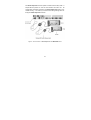
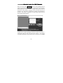
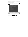
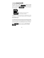
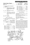
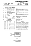
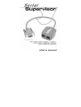
Package Content
Serial Supervisor
User’s Manual
RJ-14 Cable
x 1
x 1
x 1
Please read this manual thoroughly and follow the
Installation procedures to prevent any damage to the module or
any connecting device.
PP5-NK9700-001
Printed in Taiwan
-----------------Overview
This optional device, the Serial Supervisor, can be cascaded up to 16
Serial Supervisors by connecting to one unit of KIPS01, MNIP/UNIP,
or WMM/WUM series, controlling and monitoring up to 16 devices with
the RS-232 serial port.
These RS-232 ports may be connected to
computers, routers or other serial devices which require interactive login.
On Figure 1, it’s shown the Serial Supervisor and RJ-14 cable
physically.
There are two RJ-14 connectors and one DB-9 female
connector in the Serial Supervisor. And, RJ-14 cable is a 1 to 1 pin-out
cable by using four-conductor telephone wire.
Figure 1: The Serial Supervisor & RJ-14 Cable
Serial Supervisors are connected to the RS-232 ports of the various
devices which you need to access. Each Serial Supervisor is very
small.
Serial Supervisors are connected together in daisy-chain
fashion. The whole connection is shown in Figure 2 and Figure 3.
1
The Serial Supervisor receives power and data over the daisy-chain. A
simple RS-485 protocol is used to communicate with each unit.
All
configuration information is stored in the Serial Supervisor itself (in nonvolatile memory). This means you need not fear losing settings when rewiring the Serial Supervisor network.
Figure 2: The Connection of Serial Supervisor and MNIP/UNIP Series
2
Figure 3: The Connection of Serial Supervisor and KIPS01
3
-------------Quick Start Guide
1.
If this is the first R-Port compatible device such as the computer
you are installing, connect the RJ-14 cable (provided) to the R-Port
of KIPS01, MNIP/UNIP, or WMM/WUM series.
2.
Connect the opposite end of RJ-14 cable to the RJ-14 port of the
Serial Supervisor. There are two RJ-14 ports on the Serial
Supervisor, please feel free to pick anyone of them.
3.
Connect the DB-9 female connector of the Serial Supervisor to the
serial port of the computer.
4.
If you would like to link the second computer, please have your
second Serial Supervisor. Use the RJ-14 cable to link two Serial
Supervisors up. And, connect the DB-9 female connector to the
second computer.
5.
The LED on the top of the Serial Supervisor will blink once or
twice when first powered up, and then goes solid OFF. It will blink
ON whenever characters are being received or transmitted. The
other LED will blink when first powered up and go to solid once the
main system detects the unit and enables it.
6.
Login to the Serial Supervisor as admin. From the Home screen,
choose the Admin/Setup link from the navigation bar at the top of
the page. Click the External Serial Consoles Setup and Control
link.
7.
The Serial Supervisor compatible devices such as the computer
will be listed. To access these devices, ensure the connection
speed and other settings on this menu match the requirements of
8.
the device you are controlling.
Click the Connect button to begin a terminal session.
4
-----------------Settings
A table with all attached serial devices will be shown. Each attached
device has one line in the table. If logged-in as the admin user, the
fields in the table are editable.
Regular users cannot change any
configuration.
The columns of the table are:
#i
User defined number, from 1 to 99 that identifies a channel number and
forces the table into a particular order. It is not used for any purpose
except to sort this list, so feel free to use non-consecutive numbers, etc.
Name/Descriptioni
User defined text to label what is being controlled.
Baud (bps) i
RS-232 communication rate for that port. You must set this to match the
device being controlled. We support all common baud rates between
300 and 115,200 bps.
Modei
This indicates the character framing rules for the RS-232 connection.
Most connections are 8N1 these days, meaning eight data bits, no parity
and one stop bit. We support the following modes:
5
- 8N1 - Eight bits, no parity, one stop bit (default and most
common).
- 7N1, 7O1, 7E1, 7M1, 7S1 - Seven bits, (none, odd, even, mark,
space) parity, one stop bit.
- 8N1, 8O1, 8E1, 8M1, 8S1 - Eight bits, (none, odd, even, mark,
space) parity, one stop bit.
- 8N2 - 8 bits, no parity, two stop bits.
Force DCDi
Force the Carrier Detect signal active at all times. Normally DCD is
asserted when a new user connects, and dropped when the last user
disconnects. In this manner we emulate a modem. For some situations,
this is important for security reasons, because the remote device will
reset and logout a user when CD drops (hang up). Other devices will
get confused by CD, so they require DCD to be active at all times.
Default is off.
Console Logi
This will indicate how many lines (up to 200) of console data has been
logged. Follow the link to see the log contents on another web page. All
characters coming out of the RS-232 port go into the log. Old data is
lost once the 200 line limit is reached.
Connect... i
This button launches a Java applet which will connect back to the
product and provides terminal emulation (vt100/ansi) and scroll back.
6
If you have the
IPMI
option enabled, an addition two columns are
shown: IPMI and BMC_Password . When IPMI is enabled on a
channel, the Connect column points to another web page, rather than
the SSH client.
IPMIi
Set this to "Y" (for yes) to enable IPMI on that channel. You must set the
baud rate and other details to match your IPMI host. Most times, 19200
8N1 (force DCD) will be appropriate.
BMC_Passwordi
This is the login password for the BMC controller on the motherboard of
this port. This password is visible when you enter it, but not shown
otherwise, just an indicator that it is defined or not.
Editing this table can be done (by the admin user) very easily: just
change all the values you want, and press Commit Change . You can
change all values in the table at once without any back and forth. When
errors are found, they are reported but other changes made will still go
through.
7
-----------------How to Login Java SSH Console
When you click on the Connect... button, two new windows open as
shown in the following diagram. One is a large terminal window with a
black background. The other window is a login prompt. (This is required
because this Java program is making an SSH connection back into the
machine.) You must enter a username (or admin) and password to
proceed. Once login is completed, the small window closes and the
main window becomes useful.
Output from our system will always be shown in green, and to start, a
small banner with port name and baud rate is shown. You are now
connected interactively with the RS-232 port connected to this Serial
8
Supervisor. Anything you type will be output. Any characters received
will be shown to you when they arrive.
There is a simple menu system available at this point. Press Ctrl +
Shift + _ (underscore) to access it. Here are the menu contents:
As you can see a number of simple one-character commands are
available. Press the key of the command desired. If you follow the Ctrl
+ Shift + _ key with the command quickly, then menu is not shown and
the command just happens immediately.
End your connection with Ctrl + Shift + _ then Q .
9
-----------------How to Use IPMI
When IPMI option is enabled, addition columns appear in the main
config table. Follow the link for Sensor report to control the indicated
machine. A sensor report for all sensors on the BMC is shown on this
page, and the following Chassis Controli commands are available at
the top of the page:
Hard Reseti
Power Cyclei
Turn ONi
Turn OFFi
Pulse diag inti - Causes NMI fault, might reset machine.
Graceful OFFi - Tries to tell the O/S to shutdown.
Unfortunately, most of these commands are not implemented by current
IPMI systems. You will find most of them don't work in all circumstances.
Remote SSH login
It is possible bypass the web page login and login directly using SSH.
Using a SSH client (not provided, many free ones are available) connect
to port 22 of the system. With appropriate user name / password you
will be able to login to the Linux operating system running on our device.
Use the connect… command to connect to any Serial Supervisor.
connect –l list all units attached, and their baud rates, for example:
10
# connect -l
5 active units.
Ch# Name
Serial #
Settings
1: (none)
01e1e088090000b2
115200 bps, 8N1
2: (none)
0180078909000042
115200 bps, 8N1
3: (none)
0184e0880900009a
115200 bps, 8N1
4: (none)
01f6f28809000093
115200 bps, 8N1
5: (none)
01300989090000e7
115200 bps, 8N1
#
Using
connect X
where X is a channel number (1 to 5, in above
example) or the name of a channel, you can connect interactively to any
Serial Supervisor. The same RS-232 command menu is available
using Ctrl + Shift + _ .
11
-----------------Other Reminders
Hardware handshaking (CTS/RTS) is required at speeds over 9600bps.
It is always enabled here, but your serial device may require setup to
enable handshaking on the other end of the connection.
For UNIX
systems, the command is:
stty -crtscts < /dev/(serial port)
The Serial Supervisor network is a simple RS-485 multidrop network
running at 115,200 bps. Therefore, it follows that their will not all Serial
Supervisors may be outputting / inputting data at max speed (115,200)
all the time. We rely on the fact that this is intended for interactive login
and not all the channels will be busy at the same time. We use hardware
handshaking to limit the output rate of individual channels.
Up to four users may connect at once to the same serial port. All of
them may type commands at any time, and all see the same output.
All users have equal access to all channels.
A maximum of 16 Serial Supervisors may be attached at once.
It is safe to un-plug and re-plug the Serial Supervisor network at
anytime. No data will be lost and new nodes will be auto-detected within
15 seconds. If disconnected and reconnected, log entries will not be lost,
but they are inaccessible while unit is unplugged.
12
-----------------Appendix
Use four-conductor telephone wire, and RJ-14 connectors. These are
the connectors used on telephone handsets (between the phone base
and the thing you hold in your hand, next to your head).
Some
references call them 4P4C connectors (4 positions, 4 conductors) and
regular RJ-11's are called 6P4C connectors (6 positions, 4 conductors
although only 2 are actually used).
In this application, we require a 1 to 1 pin-out. This means if you hold up
two of the RJ-14 ends, both oriented the same way, you want pin one
(from left, say) to be connected to pin one (from left) of the other one.
This is the opposite of normal telephone wires which are reversed pinout. If using silver telephone wire, you will see a seam on one side and
not the other.
When you insert the wire into the modular plug for
crimping, one end should have the seam up and the other down.
Although counter-intuitive, this yield 1-1 pin-out.
13
Limited Warranty
IN NO EVENT SHALL THE DIRECT VENDOR'S LIABILITY FOR
DIRECT
OR
INDIRECT,
SPECIAL,
INCIDENTIAL
OR
CONSEQUENTIAL DAMAGES, LOSS OF PROFIT, LOSS OF
BUSINESS, OR FINANCIAL LOSS WHICH MAY BE CAUSED BY THE
USE OF THE PRODUCT EXCEEDS THE PRICE PAID FOR THE
PRODUCT.
The direct vendor makes no warranty or representation, expressed or
implied with respect to the contents or use of this documentation, and
especially disclaims its quality, performance, merchantability, or fitness
for any particular purpose.
The direct vendor also reserves the right to revise or update the product
or documentation without obligation to notify any user or organization of
such revisions or updates. For further information, please contact your
direct vendor.
All the brand names and registered trademarks are the property of their
respective owners.
14