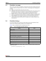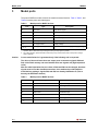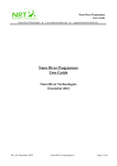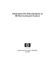
1
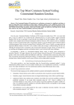
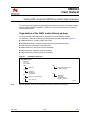
UM0423 User manual Verilog HDL model for M25Pxxx serial Flash memories This user manual describes the Verilog behavioral model for the three serial Flash memory families: M25PX, M25PE, and M25P. “ M25Pxxx” is used in this document to indicate all three different families. Organization of the VHDL model delivery package The Verilog model delivery package is organized into a main directory, named NU_M25Pxxx_VGxx.zip, containing six subdirectories with their related files (Figure 1). code subdirectory: contains model source files include subdirectory: contains parameters and constants definitions files sim subdirectory: simulation initialization files stim subdirectory: stimuli files used for simulation top subdirectory: others file used for simulation doc subdirectory: contains model documentation Figure 1. Package architecture NU_M25Pxxx_VGxx readme.txt run_ncsim run_modelsim code stim various stimuli files written in Verilog language M25Pxxx.v include doc Decoders.h DevParam.h TimingData.h top Testbench.v StimTasks.v ClockGenerator.v StimGen_interface.h M25Pxxx_UserManual.pdf sim mem_xxxx.vmf Note: July 2008 Ai12558b See the readme.txt file for the complete list of files contained in each folder. Rev 4 1/11 www.Numonyx.com Contents UM0423 Contents 1 2 Verilog behavioral model . . . . . . . . . . . . . . . . . . . . . . . . . . . . . . . . . . . . . 3 1.1 Verilog modules . . . . . . . . . . . . . . . . . . . . . . . . . . . . . . . . . . . . . . . . . . . . . 3 1.2 Header files . . . . . . . . . . . . . . . . . . . . . . . . . . . . . . . . . . . . . . . . . . . . . . . . 4 1.3 Testbench and Stimuli files . . . . . . . . . . . . . . . . . . . . . . . . . . . . . . . . . . . . . 4 Simulation guidelines . . . . . . . . . . . . . . . . . . . . . . . . . . . . . . . . . . . . . . . . 6 2.1 Launching a simulation . . . . . . . . . . . . . . . . . . . . . . . . . . . . . . . . . . . . . . . . 6 2.2 Memory file . . . . . . . . . . . . . . . . . . . . . . . . . . . . . . . . . . . . . . . . . . . . . . . . . 6 2.3 Simulation messages . . . . . . . . . . . . . . . . . . . . . . . . . . . . . . . . . . . . . . . . . 7 2.4 Simulation timings . . . . . . . . . . . . . . . . . . . . . . . . . . . . . . . . . . . . . . . . . . . 7 3 Model ports . . . . . . . . . . . . . . . . . . . . . . . . . . . . . . . . . . . . . . . . . . . . . . . . 8 4 Revision history . . . . . . . . . . . . . . . . . . . . . . . . . . . . . . . . . . . . . . . . . . . 10 2/11 UM0423 1 Verilog behavioral model Verilog behavioral model The M25Pxxx.v file of the code subdirectory contains the M25Pxxx behavioral model. It includes a set of modules that implement all the device functions listed in the datasheet. These modules use a set of parameters defined in specific header files contained in the include subdirectory. Section 1.1 and Section 1.2 describe the model's Verilog modules and the header files. Note: The model has been validated using a Cadence NC-SIM 5.7 simulator. The use with other simulators is not guaranteed. Please refer to the readme.txt file for the reference datasheet used during model development and validation. Check the Numonyx web site or contact your local Numonyx sales office for the most recent version of the device datasheet. 1.1 Verilog modules This section describes the M25Pxxx Verilog modules. M25Pxxx This is the “core” of the model, which is used to: ● latch interface signals, data, addresses, and commands ● execute read operations ● organize and control the operations of all other modules UtilFunctions This module contains utility functions used in various parts of the model. CUIdecoder This module decodes the command sequences of the Flash memory. Memory This module defines: ● the data structure used for representing the memory array ● the tasks that operate on this data structure to read, write, or erase elements of the array OTP_Memory(1) This module defines the data structure and the tasks for modeling OTP memory area. Program This module implements the algorithms that control program and erase operations. 1. These modules are only in the M25PX devices (not in M25PE and M25P devices). 3/11 Verilog behavioral model UM0423 Read This module implements certain algorithms used in read operations. LockManager This module implements the algorithms used to protect the device against program and erase operations (locking features). StatusRegister This module models the status register of the Flash memory. TimingCheck During the simulation, this module controls the timing of the input signals, to check if the related constraints are respected. Dual Ops(2) This file runs the algorithms controlling the Dual Output Fast Read and Dual Input Fast program operations. 1.2 Header files This section describes the header files used in the model. Decoders.h This file is used in M25Pxxx module. It contains all the instances of the CUI decoder module (each instance recognizes a specific command sequence of the Flash memory). DevParam.h This file contains the definitions of constants related with memory characteristics. These constants are used in various parts of the model. TimingData.h This file contains the definitions of memory's AC timing parameters. 1.3 Testbench and Stimuli files To provide an example of a complete Verilog HDL project that the user can simulate, other Verilog HDL files are offered in addition to the Flash memory model. The top subdirectory of the delivery package contains a testbench file as well as other additional files that can be used to simulate the model with various stimuli files. Stimuli files written in Verilog language are available in the stim subdirectory. These stimuli files cover many operational conditions of the device and, in particular, the CUI (command user interface) commands. 2. These modules are only in the M25PX devices (not in M25PE and M25P devices). 4/11 UM0423 Verilog behavioral model The following modules are instantiated in the Testbench.v file of the top directory: ● The StimTasks module (described in top/StimTasks.v) contains specific Verilog tasks invoked by stimuli generator module. ● The Stimuli module generates stimuli for the Flash memory by using the tasks provided by the StimTasks module. This module is implemented in various versions, each of which provide stimuli to simulate a specific device operation. The various versions of stimuli (such as read.v and program.v) are contained in the stim directory. The port interface of all stimuli files is defined in the header file top/StimGen_interface.h. The user can choose the operation to simulate by compiling a specific version of the stimuli file. For example, if the stim/read.v file is compiled, then the read operations are simulated. ● The ClockGenerator module generates clock signals that are connected as inputs to the Flash memory. Clock generation is controlled by the clock_active signal driven to ClockGenerator by the StimTasks procedures. (These procedures are activated by the Stimuli module.) ● The M25Pxxx module is the model of the serial Flash memory (device under test). Figure 2 illustrates the connections between the different modules described above. Figure 2. Testbench simulator::Testbench Tasks VCC [31:0] S HOLD VPP_W [31:0] VCC [31:0] S HOLD VPP_W [31:0] DQ0 DQ0 DQ1 DQ1 clock_active clock_active DUT StimTasks ck_gen clock_active clock_active C C ClockGenerator stim S VCC [31:0] HOLD VPP_W [31:0] S VCC [31:0] HOLD VPP_W [31:0] S S VCC [31:0] VCC [31:0] C C VPP_W [31:0] VPP_W [31:0] HOLD HOLD M25Pxxx DQ0 DQ0 DQ1 DQ1 Stimuli Testbench Ai14414 The testbench illustrated here only provides an example for driving the M25Pxxx memory model. However, users can simulate the model using his own drivers and providing specific stimuli. In this case, they must define a new Testbench.v file to link the new user's drivers to the M25Pxxx memory model. 5/11 Simulation guidelines UM0423 2 Simulation guidelines 2.1 Launching a simulation The run_ncsim file (located in the main directory) is an example of script used to launch a simulation using a Cadence NC-SIM simulator. This script compiles and elaborates: ● the Verilog M25Pxxx model (the “include” files also are considered) ● the StimTasks and ClockGenerator ● one of the stimuli files contained in the stim directory. The user can change the operations to simulate, by compiling one of the stimuli files of the stim directory. Moreover, the run_modelsim script file is provided for launching a simulation using a Mentor Modelsim simulator. 2.2 Memory file To simplify the testing of the model functions, the memory array can been loaded with specific data at power-up. The format of the memory file must be as follows: @hex_address hex_data hex_data_1 .......... hex_data is memorized at location hex_address, hex_data_1 at the location hex_address + 1, and so on. As an example: @07F 4B 9A ....... Moreover, comments are allowed in the memory file lines using the notation: / / comment The model is delivered with a template memory file called mem.vmf in the sim subdirectory. The name of memory file is defined as a parameter of the M25Pxxx module. It can be specified in the stimuli file using the following syntax: defparam Testbench.DUT.memory_file = "memory_file_name"; If the user does not provide the initialization file (memory_file:= “”), all the memory bits are set to ‘1’. 6/11 UM0423 2.3 Simulation guidelines Simulation messages When running a simulation, the M25Pxxx Verilog HDL model sends messages through the simulator console to prompt the status of the model. The following kinds of messages are provided: 2.4 ● INFO: is normal information about the device status. ● WARNING: informs the user that the result of a command sent to the memory may not be what the user expects. For example, a warning message is provided when a program operation is aborted because the page to be programmed is locked. ● ERROR: informs the user that the M25PXxx Verilog HDL model is not properly driven; that is, the provided stimuli sequence does not comply with M25PXxx specifications. ● TIMING ERROR: this message is displayed when one of the input signals of the memory (driven by the stimuli file) does not respect the AC timing constraints of the memory device. Simulation timings To reduce simulation time, the values of certain latency times can be redefined. These values can be defined by setting variables in the TimingData.h file. Table 1 lists the variables that can be redefined by the user. Table 1. User-customizable simulation timings Timing Notes program_delay erase_delay erase_ss_delay (erase subsector) M25PE and M25PX families only erase_bulk_delay write_SR_delay (Write Status Register) write_access_power_up_delay (tPUW) read_access_power_up_delay (tVSL) deep_power_down_delay M25PE and M25PX families only release_power_down_delay M25PE and M25PX families only page_write_delay M25P family only page_erase_delay M25P family only For instance, to change the program_delay to 100 ns, the program_delay constant can be redefined as follows: parameter program_delay = 100; 7/11 Model ports 3 UM0423 Model ports The ports of M25Pxxx module connect the models to external devices. Table 2, Table 3, and Table 4 list these ports and related types. Table 2. Model ports for M25PX devices Port Type Description S Input wire Chip Select signal C Input wire Clock signal HOLD Input wire Hold signal Input/output wire (1) Serial data input Input/output wire (1) Serial data output VCC [31: 0] Input wire (2) Supply voltage VPP_W [31: 0] Input wire (2) DQ0 DQ1 Write Protect/Enhanced program supply voltage 1. These ports are of type “input/output” because DQ0 is used also as output during the dual output fast read operation. DQ1 is used also as input during the dual input fast program operation. 2. The voltage signal is represented with a 32-bit binary array, whose decimal value corresponds to voltage value in millivolts. Caution: Correct model behavior is guaranteed only if the following rule is respected: The driver of the model must have two output ports connected to signals DQ0 and DQ1 of the Flash memory and must initialize these two signals at Z (high impedance value). After the initial simulation time, the values of DQ0 and DQ1 can be changed, but these signals must be Z at the simulation start time. In the testbench provided with the model delivery package, signals DQ0 and DQ1 are already initialized to Z. (This is done by the StimTasks module.) Table 3. Model ports for M25PE devices Port 8/11 Type Description S Input wire Chip Select signal C Input wire Clock signal D Input wire Serial data output Q Output wire Serial data input W Input Write Protect signal RESET Input Reset signal VCC Input wire Supply voltage UM0423 Model ports Table 4. Model ports for M25P devices Port Type Description S Input wire Chip Select signal C Input wire Clock signal HOLD Input wire Hold signal D Input wire Serial data input Q Output wire Serial data output VCC Input wire Supply voltage VPP _W Input wire Write Protect/Enhanced Program supply voltage 9/11 Revision history 4 UM0423 Revision history Table 5. Date Revision 26-Apr-2007 1 Initial release. 2 – Modified the document throughout to indicate that M25Pxxx represents the three serial Flash memory families M25PX, M25PE and M25P. – Added Dual Ops in Section 1.2: Header files. – Updated the files list in Figure 1 – Added the notes column toTable 1. – Added the timing error message in Section 2.3. – Modified Table 2 for model ports specific to the M25PX family, and added Table 3, and Table 4 for the M25PE and M25P families. 21-Aug-07 3 Updates made in accordance with updates in the M25PX32 datasheet: – Moved the section on the dual ops header file to Section 1.1. – Replaced Figure 2: Testbench. – Removed VPP from Table 2: Model ports for M25PX devices and added the VPP_W values. 31-Jul-08 4 Applied Numonyx branding. 9-Jul-07 10/11 Document revision history Changes UM0423 Please Read Carefully: INFORMATION IN THIS DOCUMENT IS PROVIDED IN CONNECTION WITH NUMONYX™ PRODUCTS. NO LICENSE, EXPRESS OR IMPLIED, BY ESTOPPEL OR OTHERWISE, TO ANY INTELLECTUAL PROPERTY RIGHTS IS GRANTED BY THIS DOCUMENT. EXCEPT AS PROVIDED IN NUMONYX'S TERMS AND CONDITIONS OF SALE FOR SUCH PRODUCTS, NUMONYX ASSUMES NO LIABILITY WHATSOEVER, AND NUMONYX DISCLAIMS ANY EXPRESS OR IMPLIED WARRANTY, RELATING TO SALE AND/OR USE OF NUMONYX PRODUCTS INCLUDING LIABILITY OR WARRANTIES RELATING TO FITNESS FOR A PARTICULAR PURPOSE, MERCHANTABILITY, OR INFRINGEMENT OF ANY PATENT, COPYRIGHT OR OTHER INTELLECTUAL PROPERTY RIGHT. Numonyx products are not intended for use in medical, life saving, life sustaining, critical control or safety systems, or in nuclear facility applications. Numonyx may make changes to specifications and product descriptions at any time, without notice. Numonyx, B.V. may have patents or pending patent applications, trademarks, copyrights, or other intellectual property rights that relate to the presented subject matter. The furnishing of documents and other materials and information does not provide any license, express or implied, by estoppel or otherwise, to any such patents, trademarks, copyrights, or other intellectual property rights. Designers must not rely on the absence or characteristics of any features or instructions marked “reserved” or “undefined.” Numonyx reserves these for future definition and shall have no responsibility whatsoever for conflicts or incompatibilities arising from future changes to them. Contact your local Numonyx sales office or your distributor to obtain the latest specifications and before placing your product order. Copies of documents which have an order number and are referenced in this document, or other Numonyx literature may be obtained by visiting Numonyx's website at http://www.numonyx.com. Numonyx StrataFlash is a trademark or registered trademark of Numonyx or its subsidiaries in the United States and other countries. *Other names and brands may be claimed as the property of others. Copyright © 2008, Numonyx, B.V., All Rights Reserved. 11/11