1
RanchMaster System
Installation Guide
RanchMaster System
Installation Guide
April 2010
(V5.01)
April 2010
(V5.01)
CONTENTS
Warranty Coverage...................................................................4
ABOUT THIS GUIDE AND OTHER RESOURCES...................5
SYSTEM COMPONENTS.........................................................6
INSTALLING A WEATHER STATION.......................................8
Unpack and Verify Components......................................................................................................9
2. Verify that Base Station powers up...........................................................................................10
3. Verify that Base Station connects to Server............................................................................12
4. Verify sensor data in the on-line application.............................................................................13
Installation of Base Station............................................................................................................15
7. Connect Sensors to Weather Station........................................................................................19
6. Solar Panel Assembly................................................................................................................20
8. Assembling Radiation Shield.....................................................................................................23
9. Assembling Rain Gauge............................................................................................................24
9. Testing the rain gauge...............................................................................................................25
10. Configuration of wind direction................................................................................................27
INSTALLING SENSOR NODES..............................................29
1. Installing an RS-210 Node in the field.......................................................................................31
1. Installing an RS-100 Node in the field.......................................................................................32
2. Connect Sensors to Sensor Node.............................................................................................33
3. Verify that Nodes are transmitting to Base Station...................................................................36
INSTALLING OTHER SENSORS AND EQUIPMENT.............38
Installing Pyranometer...................................................................................................................38
Installation of inline water flow meters..........................................................................................39
................................................................................................41
INSTALLING BATT 55 UPG....................................................42
...............................................................................................43
INSTALLING AQUASPY PROBES.........................................44
WIRING DIAGRAMS...............................................................48
FURTHER HELP.....................................................................49
© Ranch Systems LLC, 2005-2008. All Rights Reserved. Reproduction without permission from Ranch Systems is prohibited.
3
Warranty Coverage.
Ranch Systems' warranty obligations are limited to the terms set forth below: Ranch Systems
LLC ("RS") warrants hardware products manufactured and sold by RS against defects in
materials and workmanship for a period of TWO (2) YEARS from the date of original purchase.
If a defect exists, at its option RS will (1) repair the product at no charge, (2) exchange the
product with a new product that is at least functionally equivalent to the original product, or (3)
refund the purchase price of the product. A replacement product/part assumes the remaining
warranty of the original product or ninety (90) days from the date of replacement or repair,
whichever provides longer coverage. When a product or part is exchanged, any replacement item
becomes customer's property and the replaced item becomes RS's property. When a refund is
given, the defect product becomes RS's property.
It is the sole and exclusive responsibility of Customer to determine the suitability of any and all
products for the Customer’s use. THERE ARE NO EXPRESS OR IMPLIED
WARRANTIES OF RANCH SYSTEMS BEYOND THE WARRANTY SET FORTH IN
THIS SECTION ABOVE. THIS EXCLUSION MEANS THERE IS NO IMPLIED
WARRANTY OF MERCHANTABILITY AND NO IMPLIED WARRANTY OF
FITNESS FOR ANY PARTICULAR PURPOSE. THIS EXCLUSION ALSO MEANS
THAT RANCH SYSTEMS GRANTS NO IMPLIED WARRANTY ARISING BY USAGE
OF TRADE, COURSE OF DEALING OR COURSE OF PERFORMANCE, AND NONE
SHALL ARISE OUT OF ANY SALE UNDER THIS AGREEMENT OR OUT OF
EITHER PARTIES' CONDUCT.
Obtaining Warranty Service.
To obtain warranty service customer must deliver the product to the nearest wholly-owned
Ranch Systems facility at customer's expense. Ranch Systems will return repaired product at
Ranch Systems' expense by common carrier – such as UPS or Fedex - to any return address
within the United States as directed by customer. For return service outside the United States,
customer is responsible for costs in excess of the common carrier cost to ship to nearest major
city inside the United States.
Limited Liability.
Ranch Systems shall not be liable for direct, indirect, incidental or consequential damages,
including, without limitation, damages or harm to business, lost profits or lost revenues
(however arising, including negligence), whether or not Ranch Systems has been advised of the
possibility of such damages. Ranch Systems shall not be liable for any damage that Customer
may suffer arising out of the use, or inability to use, the services or products provided hereunder.
The liability of Ranch Systems for any claim by any party arising out of or in connection with
the services or products provided hereunder shall not exceed the amount paid to Ranch Systems
by Customer with respect to the sale of the specific product or services cited in such claim.
Customer shall indemnify and hold Ranch Systems harmless from and against any and all
liabilities, losses, damages, costs, expenses awarded against Customer in connection with any
third party claim, action, or right of action, at law or in equity, arising out of bodily injury,
property damage, or any other damage or injury caused by Customers use of the Ranch Systems
Solution.
4
© Ranch Systems LLC, 2005-2008. All Rights Reserved. Reproduction without permission from Ranch Systems is prohibited.
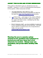
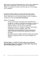
ABOUT THIS GUIDE AND OTHER RESOURCES
This guide is intended to get you started as soon as
possible. However, it is not a comprehensive description
of the system. Other resources include:
✔
The RanchMaster User Manual. This
comprehensive document is available as PDF file
through the www.ranchsystems.com website.
✔
Online help – each page in the online software
contains help information right on the page in
the upper left hand corner, indicated by the blue
question mark icon.
✔
Ranch Systems staff – we are available to respond
to your questions directly as time permits. The best
way to reach us and be sure of a comprehensive
reply is to use email:
[email protected].
Warning: Be sure to exercise safety
procedures for machines and equipment to
protect yourself from injury that could
otherwise be avoided. Always wear eye
protection, and gloves while working with
tools.
© Ranch Systems LLC, 2005-2008. All Rights Reserved. Reproduction without permission from Ranch Systems is prohibited.
5
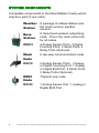
SYSTEM COMPONENTS
Compatible components in the RanchMaster Family which
may be a part of your order.
Weather A package of a Base Station and
the most common weather
Station
sensors.
6
Base
Station
A triple band wireless networking
node. This is the main online link
for all nodes.
RM210
4 Analog Sensor Ports, 2 Digital
Counting Ports, 2 Serial Ports, 4
Relay Ports (Optional).
Mesh
Node
A two-way communications node
RS210
3 Analog Sensor Ports, 1 Analog
or Digital Counting Port, 1 Analog
or Digital BUS Port, 2 Serial Ports,
3 Relay Ports (Optional).
RSRF
Node
Transmit only node.
RS100
1 Analog Sensor Port, 1 Analog or
Digital BUS Port
© Ranch Systems LLC, 2005-2008. All Rights Reserved. Reproduction without permission from Ranch Systems is prohibited.
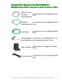
Compatible Sensors for RanchMaster
Equipment which may be a part of your order.
Micro Probe
Connects to an Analog Sensor
Analog
Port
Temperature
Analog
Connects to an Analog Sensor
Temperature Port
Humidity
Connects to an Analog Sensor
Port
Wind Speed Connects to a WSWD Port, or
and Direction two Analog Sensor Ports
Rain Gauge
Connects to a Digital Counter
Port
Pyranometer
Connects to an Analog Sensor
Port
© Ranch Systems LLC, 2005-2008. All Rights Reserved. Reproduction without permission from Ranch Systems is prohibited.
7
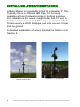
INSTALLING A WEATHER STATION
A Base Station is intended to mount to a standard 3” Pipe.
Typically this is a 3” Black ABS Pipe, 10 feet long,
available at most hardware stores or building supplies.
For installations that need a height taller than 10 feet, a
telespar antenna mast or 3” Steel pipe is recommended.
This is usually a 20-30 foot pipe cast into concrete 5 feet
into the ground.
A detailed explanation of where to install the Station is in
Section 5.
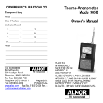
Illustration 1: Weather Station mounted to 35'
Telespar Antenna Mast
8
Illustration 2: Standard Weather Station
Installed on 10' x3” ABS Pipe
© Ranch Systems LLC, 2005-2008. All Rights Reserved. Reproduction without permission from Ranch Systems is prohibited.
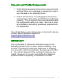
Unpack and Verify Components
1. Verify that all equipment has been received intact
and that there is no damage to equipment, note if
any damage to the shipping boxes.
2. Check that all items on packaging list have been
received per sales order, and that there nothing is
missing. This is a good time to get aquainted with
the components with your order. Be sure to read
all installation and safety guidelines supplied with
the equipment.
If you think that you are missing any components, please
contact Ranch Systems support at
[email protected]
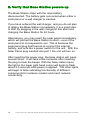
IMPORTANT
It is a good idea to follow the verification steps in the
following sections first, in order, before installing. Any
number of problems could have happened in shipping.
You may also start the installation by skipping to Section
5. You will be referred to the verification steps as you
install. However, it is much more difficult to diagnose
problems when everything is mounted in the field.
© Ranch Systems LLC, 2005-2008. All Rights Reserved. Reproduction without permission from Ranch Systems is prohibited.
9
2. Verify that Base Station powers up
The Base Station ships with the main battery
disconnected. The battery gets connected when either a
solar panel or a wall charger is inserted.
If you have ordered the wall charger, and you do not plan
to deploy the Base Station immediately, it is a good idea
to start by plugging in the wall charger at this point and
charging the Base Station for 24 hours.
Alternatively, you may insert the solar panel immediately,
which will prompt the Base Station to start – even if the
solar panel is not exposed to sun. This is because the
solar panel plug itself serves to connect the internal
battery, and acts like a power switch for the unit. With the
Solar Panel plug inserted into port 1 the unit will turn on.
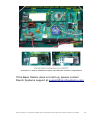
After inserting the power plug, the base station will beep
several times. It will take a few moments after inserting
the plug to hear the beeps. With the base station open,
the light in the lower right hand corner will begin to flash
about 2-5 seconds after power is applied. The other lights
will begin to blink indicating functionality of different
components for instance modem and mesh network
connectivity.
10
© Ranch Systems LLC, 2005-2008. All Rights Reserved. Reproduction without permission from Ranch Systems is prohibited.
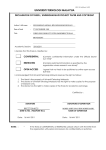
Illustration 3: RM210 Mainboard layout with alternate modem configurations
If the Base Station does not start up, please contact
Ranch Systems support at [email protected]
© Ranch Systems LLC, 2005-2008. All Rights Reserved. Reproduction without permission from Ranch Systems is prohibited.
11
3. Verify that Base Station connects to
Server
Make sure that the Base Station is placed somewhere
with adequate cellular connection. Ranch Systems uses
GSM, CDMA cellular signal, or WiFi depending on what
you ordered.
Certain types of cell phones can be used to gauge if there
is signal:
–
–
–
Phones from Cingular, Edge Wireless, and T-Mobile are
typically GSM.
Phones from Sprint or Verizon are typically CDMA.
Nextel is not typically GSM or CDMA.
Once the Base Station is turned on, and adequate signal
is available, it should begin to synchronize with the Ranch
Systems server. Give it a few minutes to get connectivity
and synchronize before starting to troubleshoot.
When first powered up, the time of the unit will not be
correct. With a successful Internet connection, the system
will discover this and the time will be adjusted, and the unit
will reset automatically. You will hear the same series of
initial beeps again as this happens.
At this point the Base Station is running and logging
receiving sensor information from nearby nodes. All the
programming of functionality is done in the Internet
software.
You should now check online to see if recent data is
present. It may take up to half an hour for the first set of
data to show up with the correct time.
If the Base Station does not start up, please contact
Ranch Systems support at [email protected]
12
© Ranch Systems LLC, 2005-2008. All Rights Reserved. Reproduction without permission from Ranch Systems is prohibited.
4. Verify sensor data in the on-line application
Whether you checked the data arriving to the Base
Station, or not, the most important test is to verify that
sensor data is arriving correctly into the on-line
application.
Go to www.ranchsystems.com and click the “My Account”
link on the upper left side.
Log in using three pieces of information:
●
●
●
The Property ID. This is a short ID describing the
property where a particular Base Station and node
will be deployed. Several users may have access
to any given property.
User ID. This is an ID of a particular user. A user
may have access to multiple properties.
Password. This is the user-specific password.
You will receive an email with this information from Ranch
Systems before you receive your system. If not, contact
support at [email protected].
Now you should see a map with your Base Station and
nodes clearly visible as little green icons. Try clicking on
any of them, and you'll see a a graph of all the sensor
data associated with that station or node (even system
data, like battery levels).
You will also see specific sensors listed below the green
icons. These are the sensors that have been specifically
assigned to a zone or block. By default all the external
sensors are assigned to a default block called “Default” indicated on the map by a green, square box. Try clicking
anywhere inside this box, but not on a node or sensor
icon. You will see a zone/block graph, showing all the
sensors assigned to this block (irrespective of which node
© Ranch Systems LLC, 2005-2008. All Rights Reserved. Reproduction without permission from Ranch Systems is prohibited.
13
they are attached to).
You can also try clicking on a specific sensor icon. This
will produce a graph of only that sensor's data.
Click through the various nodes and sensors, getting
familiar with the system. If some data seems to be
missing, contact Ranch Systems support at
[email protected].
Once you have deployed the hardware, you will want to do
the following:
1. Upload an overview image of your particular
property, such as an aerial photo or map (using
Zone Definitions screen)
2. Define each of your irrigation blocks or zones
(using Zone Definitions screen)
3. Attach specific nodes and sensor to blocks (using
Sensor Assignment screen)
4. Place nodes and sensors on the map (using
Sensor Assignment screen)
Note that you can assign same sensor to several zones,
and it is often useful to create “virtual” zones that combine
sensors in different, non-geographic ways. You can even
draw these virtual zones on your map as little “buttons” for
easy access.
Please read the software section in this manual for more
information regarding setting up the online software, if you
have any questions please contact Ranch Systems
support at [email protected]
14
© Ranch Systems LLC, 2005-2008. All Rights Reserved. Reproduction without permission from Ranch Systems is prohibited.
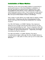
Installation of Base Station
Selection of the site for the Base Station is essential for
good performance of the RanchMaster installation. It
should generally be placed at the highest point in the
topographical area where it has a good line-of-sight to
each deployed sensor node. If you ordered a solar panel,
good southern exposure is also necessary for charging
the unit (out of the shade of trees or buildings).
Also, keep in mind where you might want to deploy nodes
in the future. Planning now for a development in the
future can save time moving the equipment for a better
location.
For RS-100 Nodes (or RSRF Nodes), the maximum
distance line-of-sight cannot generally exceed 1/3 mile,
and should preferably be less. If your vineyard is flat, the
distance will generally have to be less as the line-of-sight
is subject to “ground interference” - especially as foliage
increases during the season.
For RS-210 Nodes (or Mesh Nodes), the same
considerations apply, although the line-of-sight distance
can be up to 1 mile with 2.4 Ghz, and up to 2.5 miles with
900mhz.
© Ranch Systems LLC, 2005-2008. All Rights Reserved. Reproduction without permission from Ranch Systems is prohibited.
15
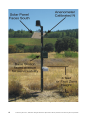
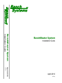
Illustration 4: Typical Base Station mounting on 3” ABS drain pipe
16
© Ranch Systems LLC, 2005-2008. All Rights Reserved. Reproduction without permission from Ranch Systems is prohibited.
The Base Station comes supplied with a mounting bracket
assembly with metal bands that will fit around a variety of
posts, both round and square. The ideal size of post is 3”,
and very often a 3” Non-perforated ABS drainpipe is used,
which can be secured to another post, such as a trellis
end post or eight foot t-post. However, any tall, sturdy
wooden pole, ABS, PVC or steel pipe will work. The pipe
should be straight, and plumb.
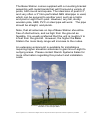
Note, that all antennas on top of Base Station should be
free of obstructions, and as high from the ground as
feasible. It is usually preferred that the unit is roughly 5 to
6 feet from the ground. However, the higher the Base
Station the more likely range will increase to the nodes.
An extension antenna kit is available for installations
requiring higher elevation antennas to gain line-of-sight to
outlying areas. Please contact Ranch Systems Sales for
more information regarding this product and installation
costs.
Illustration 5: Base station with Antenna extension
mounted on 30' Telespar Mast
© Ranch Systems LLC, 2005-2008. All Rights Reserved. Reproduction without permission from Ranch Systems is prohibited.
17
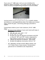
If you use a 3” ABS pipe, and you are installing the
Weather Station Package, you might consider drilling 1.5”
holes at various heights along the pipe to accommodate
Illustration 6: Drilling base station pole with
hole locations marked on 3/4” PVC
running wires inside the pipe which both protects cables
and leaves a neat appearance when the cables are tucked
away inside the pipe, minimizing damage potential to
cables.
Typical base station pole: hole locations (10'x3” ABS
Pipe):
•
Measure from bottom of pole and mark with tape or
otherwise:
1. 36”, 60”, 80”, 96”, 104”, 112”
2. At 36” drill 1½” Hole
3. Rotate the pipe 90 degrees clockwise and drill
on the 60”, 80” and 104” marks, keeping the
pipe fixed so holes are on one side of pipe
4. Rotate 45 degrees clockwise. Drill at 96”
5. Rotate 90 degrees clock wise. Drill at 112”
•
18
36”=Radiation shield; 60-80”=Base station; 96112”=Solar Panel, Anenometer, Pyranometer
(placement is installation-site dependent)
© Ranch Systems LLC, 2005-2008. All Rights Reserved. Reproduction without permission from Ranch Systems is prohibited.
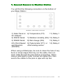
7. Connect Sensors to Weather Station
You will find the following connectors on the bottom of
your Base Station:
Illustration 7: Base Station Connectors
1) Solar Panel or 6) Temperature (TP)
AC Adapter
11) Relay 1
2) RS232 Serial
7) Relative Humidity (RH) 12) Relay 2
3) RS485 Serial
8) Rain Gauge (RG)
4/5) Wind Speed 9) Pyranometer (PY); or
and Direction
other analog sensor
(WS/WD)
13) Relay 3
14) Relay 4
When using a drilled pipe, be sure to clean the hole of any
burrs or sharp edges that may cut the cable, then run
each cable through the pipe before connecting. When
using a solid pipe or pole, connect all cables first, then
secure the cables to the pole or pipe with zip ties.
© Ranch Systems LLC, 2005-2008. All Rights Reserved. Reproduction without permission from Ranch Systems is prohibited.
19
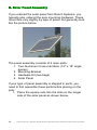
6. Solar Panel Assembly
If you ordered the solar panel from Ranch Systems, you
typically also ordered the pole mounting hardware. These
mount kits vary slightly by type of panel, but generally look
like the picture below.
Illustration 8: Solar Panel Assembly
The panel assembly consists of 4 main parts:
1. Two Aluminum Cross-members (1/2” x 18” angle
pieces)
2. Mounting Bracket
3. Hardware Kit (two bags)
4. Solar Panel
If your type of panel assembly is shipped in parts, you
need to first assemble these parts before placing on the
pole:
1. Place the square nuts into the slots on the longer
side of the solar panel as shown below.
20
© Ranch Systems LLC, 2005-2008. All Rights Reserved. Reproduction without permission from Ranch Systems is prohibited.
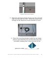
Illustration 9: Nut and Screw Installation
2. Place the aluminum angle pieces over the nuts and
align the hole with the nuts. Install all screws loose
enough for the aluminum cross-member to move.
Illustration 10: Nut and Screw Installation
3. Place the mounting bracket inside the two angle
pieces, and install the four screws with lock-nuts
provided, keeping them loose enough for the
pieces to rotate.
Illustration 11: Nut and Screw Installation
© Ranch Systems LLC, 2005-2008. All Rights Reserved. Reproduction without permission from Ranch Systems is prohibited.
21
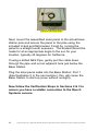
Illustration 12: Assembled Solar Panel,
(exposure side facing down)
Next, mount the assembled solar panel to the actual base
station pole and secure the panel to the pole using the
included U-bolt and flat bracket. Finish by turning the
panel to a straight south exposure. The bracket should be
made for at an appropriate angle to the sun for your
location, typically 45 degrees for California.
If using a drilled ABS Pipe, gently pull the cable down
through the pipe and out an adjacent hole just below the
Base Station.
Plug the solar panel cable into the Base Station: Port 1
(See Illustration 5 in the next section), this will cause the
Base Station to start-up (even without sunlight).
Now follow the Verification Steps in Sections 2 & 3 to
assure you have a reliable connection to the Ranch
Systems servers.
22
© Ranch Systems LLC, 2005-2008. All Rights Reserved. Reproduction without permission from Ranch Systems is prohibited.
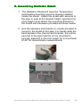
8. Assembling Radiation Shield
1. The Radiation Shield will have the Temperature
and Relative Humidity sensors already installed
inside the shield. Attach the shield with sensors to
the pipe or pole at the desired height, typically fruit
zone height. First attach the mounting bracket to
the shield with hardware provided as shown below.
2. Use the stainless steel bands or u-bolts provided to
mount to the shield to the pipe. For bands slide the
band between the channel and bracket, this will be
secured to the pipe that the unit is mounted to
typically adjacent to the fruit height for microclimate
or 48” for mesoclimate measurements
Illustration 13: Attach bolts and mounting
bracket
Illustration 14: Bolt and spacer installation on
Radiation Shield
© Ranch Systems LLC, 2005-2008. All Rights Reserved. Reproduction without permission from Ranch Systems is prohibited.
23
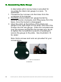
9. Assembling Rain Gauge
A steel plate with 6 screw holes is provided for
mounting the black rain gauge to a pole. To
assemble:
1. Thread the four screws into the holes from the
underside of the bracket.
2. Carefully remove black rain gauge bucket by
twisting counter-clockwise and lifting away from the
base, once the bucket is disengaged.
3. Align the notch at the bottom of the black rain
gauge to the right-angle on the plate, and insert the
screws into the rain gauge. Place the included nuts
over the screws and tighten the screws only (so as
to tighten the nut without a wrench or twisting) to
secure the gauge to the plate. See illustration 15
for detail
Note: Extra screws and nuts are provided for your
convenience.
Illustration 15: Screw pattern for underside of
RG Bracket
24
© Ranch Systems LLC, 2005-2008. All Rights Reserved. Reproduction without permission from Ranch Systems is prohibited.
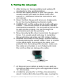
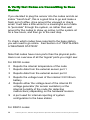
9. Testing the rain gauge
1. After turning on the base station and waiting 30
minutes for a time synchronization
2. Access the tipping bucket of your rain gauge – this
usually means you twist the whole 'hood' and
remove it. Otherwise follow the instructions with
your gauge.
3. Open the Rain Gauge and remove a shipping zip
tie on the moving tipping mechanism inside.
4. CAREFULLY cut the yellow zip tie inside with wire
cutters. It can be very close to the wires, and the
mechanism is sensitive. Do not push or pull on the
tie with a knife or blade, this can damage the
mechanism and void the warranty.
5. Now manually tip the silver cups inside the gauge 5
times. 5 is usually good and easy to remember,
this would show up online as 0.05 inches of rain.
6. Replace the bucket on the gauge, exercise caution
to avoid pinching the sensor cable. There is a notch
in the plastic base that receives the cable, and
protects from the locking of the bucket, make sure
the cable is not twisted or out of alignment inside
the notch as this can damage the cable.
Illustration 16: Be sure cable is not pinched
when securing bucket to bracket
7. At this point your station is ready to use, and you
should see data entering the web application within
15 - 30 minutes.
8. A U-Bolt is provided for a 3” Pipe, this should be
about 2 inches from the top of the pipe, leaving the
© Ranch Systems LLC, 2005-2008. All Rights Reserved. Reproduction without permission from Ranch Systems is prohibited.
25
top of the rain gauge well above the pipe.
Note: In some locations aviary defense is needed
to deter droppings and ultimately the clogging of
the rain gauge. However, we recommend
researching local laws before attempting to put
spikes on the gauge, as other methods such as
higher perch areas, predatory birds, and more
frequent cleaning are suitable options. Bird Spike
Installation kits are available from Ranch Systems.
Illustration 17: Bird Spike Kit
26
© Ranch Systems LLC, 2005-2008. All Rights Reserved. Reproduction without permission from Ranch Systems is prohibited.
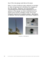
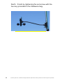
10. Configuration of wind direction
1. Assemble the Wind Speed and Direction sensors
with the hardware, per the manufacturers directions
included in the box.
2. Using the bands or u-bolts provided in the box,
mount the sensor to the pipe.
3. Point the sensor arm in a direction so as to
encounter the prevailing winds.
4. Connect the sensor to the unit in the appropriate
port.
Wind direction is the only sensor that needs specific
configuration. Note: You will need a compass or know
exactly which direction North is to do the following:
Illustration 18: The mark on the spindle or wind direction axle will align with the
armature.
1. After the Anemometer has been assembled and
mounted to the pole, remove the weather vane
(wind direction pointer). The black line on the
spindle needs to be aligned with the support arm.
This is the calibration mark for the sensor.
2. Place the weather vane (wind direction pointer) on
the upper spindle pointing the vane exactly North.
Be careful not to move the spindle as you sight out
© Ranch Systems LLC, 2005-2008. All Rights Reserved. Reproduction without permission from Ranch Systems is prohibited.
27
North. Finish by tightening the set screw with the
hex key provided in the hardware bag.
Illustration 19: Installation on a 3/4” EMT Conduit for an RS-210
28
© Ranch Systems LLC, 2005-2008. All Rights Reserved. Reproduction without permission from Ranch Systems is prohibited.
INSTALLING SENSOR NODES
The key to a good node installation is achieving a clear
line-of-sight connection to the base station, ensuring good
data connectivity at all times. Nodes should be placed well
above maximum crop canopy height.
The RS100 and RS210 nodes have been manufactured to
be installed with easily available materials such as: 1” or
¾” White PVC pipe or ¾” EMT Conduit pipe, UV
resistant zip-ties and Stainless Steel Hose Clamps.
These types of pipes are already widely used so the pipe,
fittings and tools are readily available at low cost. The
result is faster and less expensive installations. They are
usually purchased in 10' lengths, which makes a good
height for most locations, as long as overhead farming
and picking equipment will not be a factor in the
installations.
Illustration 20: RS-210 Micro-climate Weather
Station
© Ranch Systems LLC, 2005-2008. All Rights Reserved. Reproduction without permission from Ranch Systems is prohibited.
29
Often we recommend attaching the node to the installation
pipe before attaching to the line post, as a small bull
ladder is required to reach up to the top of a 10 foot pipe
once installed.
As with the base station, ensure that the each units
antennas are free of obstructions as well as potential
future obstruction from growing foliage (note: consider a
clearance of at least two feet minimum).
Notes to Consider:
•
Leave a Service Loop at the end of cables and
anywhere a cable is exposed and likely to moved or
pulled, so as to reduce wear on connectors and
reduce chance of a rip-out of connector.
•
Placing sensors out of path of danger from heavy
machines, pruners, paddles, discs, etc.
•
Collapsible mounting poles to lower equipment
while overhead mechanized equipment passes
through.
•
Protecting sensor cables with PVC pipes and proper
fittings to reduce chance of cuts and pulled out
cables
Follow steps 1 and 2 for each node you received.
Then follow step 3 to verify all nodes after they have
had 15-30 minutes to report.
30
© Ranch Systems LLC, 2005-2008. All Rights Reserved. Reproduction without permission from Ranch Systems is prohibited.
1. Installing an RS-210 Node in the field
RS210 Nodes are shipped with an integrated mounting
assembly which holds both the solar panel in place, as
well as a ¾” EMT Conduit connector. All you need is to
attach a ¾” EMT Conduit pipe to a line post in the
vineyard (using metal bands) and hand-tighten the nut
with the RS210 node on top.
Illustration 21: RS210 Node
Illustration 23: RS210 Node
Assembly ready to deploy on 3/4”
EMT Conduit pipe.
Illustration 22: RS210 Deployed on 10'
Conduit pipe.
© Ranch Systems LLC, 2005-2008. All Rights Reserved. Reproduction without permission from Ranch Systems is prohibited.
31
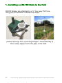
1. Installing an RS-100 Node in the field
RS100 Nodes are attached to a ¾” four-way PVC tee
using two UV/weather resistant tie wraps
Illustration 24: RS100 Sensor Node Assembly
Illustration 25: RS100 Deployed on 10'
PVC pipe
passed through their mounting flanges. The assembly is
then easily slipped onto the pipe in the field.
32
© Ranch Systems LLC, 2005-2008. All Rights Reserved. Reproduction without permission from Ranch Systems is prohibited.
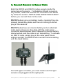
2. Connect Sensors to Sensor Node
Both the RS100 and RS210 nodes accept mostly the
same types of sensors. If a Radiation Shield is used on
any sensor, make the sensors are mounted in the shield
by follow the section “INSTALLING RADIATION SHIELD”
before you connect them to the node.
RS100 Nodes come completely ready, meaning they are
already transmitting data, and there is nothing to do but
plug in the sensors.
RS210 Nodes have an internal battery and an attached
solar panel. However, they ship with the solar panel
connector disconnected, which leaves the internal battery
disconnected, and the node is not transmitting. To activate
an RS210 node, simply plug in the solar panel. Even
without sunlight, the RS210 will now start communicating
with the base station.
Illustration 27: RS210 Node
Illustration 26: RS100 Node
For both types of nodes, you must make sure the right
sensors are plugged into the right ports.
© Ranch Systems LLC, 2005-2008. All Rights Reserved. Reproduction without permission from Ranch Systems is prohibited.
33
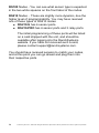
RS100 Nodes - You can see what sensor type is expected
in the two white squares on the front label of the nodes.
RS210 Nodes - These are slightly more dynamic, due the
higher level of programmability. You may have received
one of these types of RS210 nodes:
● RS210-S has 6 sensor ports.
● RS210-PRO has 6 sensor ports and 3 relay ports.
The initial programming of these ports will be listed
on a card shipped with the unit, and should be
available after logging into the RanchSystems
website. If you have not received such a card,
please contact [email protected].
You should have received sensors to match your nodes,
and at this point you can go ahead and plug them into
their respective ports.
34
© Ranch Systems LLC, 2005-2008. All Rights Reserved. Reproduction without permission from Ranch Systems is prohibited.
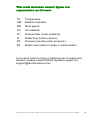
The most common sensor types are
represented as follows:
TP
Temperature
HM
Relative Humidity
WS
Wind speed
UV
UV radiation
PY
Pyranometer (solar radiation)
FL
Water flow (turbine sensor)
PS
Pressure (usually water pressure)
WL
Water Level (either in-pipe or submersible)
If you don't seem to have a matching set of nodes and
sensors, please contact Ranch Systems support at
[email protected]
© Ranch Systems LLC, 2005-2008. All Rights Reserved. Reproduction without permission from Ranch Systems is prohibited.
35
3. Verify that Nodes are transmitting to Base
Station
If you decided to plug the sensor into the nodes and do an
indoor “bench test”, this is a good time to go and make a
fresh pot of coffee, drive around the vineyard or check
email. It will take a little while for a meaningful set of data
to “percolate” through the system, so rather than wait
around for the nodes to show up online, let the system sit
for a few hours, and then go to the next step.
To check which nodes have reported to the base station,
you will need to go online. See Section 4 of “INSTALLING
A WEATHER STATION”.
Note that nodes have more ports than the physical ports.
Here is an overview of all the 'logical' ports you might see:
For RS100 nodes:
0 Reports the internal temperature of the node
1
Reports data from the external sensor port 1
2
Reports data from the external sensor port 2
3
Reports the voltage level of the internal 3.5V lithium
battery
4
Reports either the voltage level of the internal 5V
voltage generator (for sensor excitation) or the
internal humidity of the node (for detecting
malfunctions) depending on the hardware revision.
9
A port used for internal reporting of system
configuration to the base station
For RS210 nodes:
36
© Ranch Systems LLC, 2005-2008. All Rights Reserved. Reproduction without permission from Ranch Systems is prohibited.
0
Reports the internal temperature of the node
1
Reports data from the external sensor port 1
2
Reports data from the external sensor port 2
3
Reports data from the external sensor port 3
4
Reports data from the external sensor port 4
5
Reports data from the external sensor port 5
6
Reports data from the external sensor port 6
7
Reports status of relay 1
8
Reports status of relay 2
9
Reports status of relay 3
10 A port used for internal reporting of system
configuration to the base station
© Ranch Systems LLC, 2005-2008. All Rights Reserved. Reproduction without permission from Ranch Systems is prohibited.
37
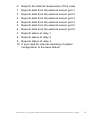
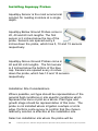
INSTALLING OTHER SENSORS AND
EQUIPMENT
Installing Pyranometer
A Pyranometer measures the radiation from the sun in
watts per meter square. It is used specifically to gather
evapotranspiration (ETO) readings.
The sensor must be directed by turning the bracket or
turning the sensor itself so that the wire from the black
dome sensor faces north. A leveling plate is provided to
aid in achieving more accurate results, Use the Hex key
provided to adjust the height of the plate if necessary.
A mounting bracket is provided to attach to the base
station pole or node pole.
Illustration 28: Pyranometer Assembly
38
© Ranch Systems LLC, 2005-2008. All Rights Reserved. Reproduction without permission from Ranch Systems is prohibited.
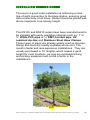
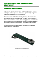
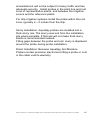
Installation of inline water flow meters
Illustration 29: Irrigation Monitoring with
inline rotary flowmeter and Aquaspy soil
moisture sensor
Installation into various sizes of tubing or pipe is possible
with a variety of fittings, however the most important factor
to consider is flow rate. Please consult with the table
below to best understand the flow rate for your meter.
Note: Restricted flow rates, are achieved with the plastic
insert provided with the flow meter, and can alter the
water pressure, can clog, and are not as accurate as
unregulated flow, be sure to check flow often or setup
feedback alerts (covered in the user manual: Online
Software).
Size Inlet
Minimum
Std. Flow Rate
Minimum
Restricted Flow
Rate
.25”
.5-1.0 GPM/30-60GPH
.1-.3GPM/.618GPH
.75”
N/A
1”
N/A
© Ranch Systems LLC, 2005-2008. All Rights Reserved. Reproduction without permission from Ranch Systems is prohibited.
39
•
Important flow meter installation considerations:
1. Flow rate across the sensor, is dependent on
the amount of drippers or otherwise that are
'down tube' from the meter.
2. The viewing window should be facing north if
possible, and covered with a plastic opaque
plate (to reduce growth inside tubing).
3. Consider protecting the sensor cable with
PVC piping to the sensor, make sure that the
pipe is secured in 2-3 places so that it
doesn't move freely.
4. Consider adding service loops nearby the
sensor where a few loops around the hand
and securing to a nearby post or pipe with
zip ties allows slack in the event that service
is needed to be performed on the sensor or
poly tube.
Illustration 30: Flowmeter with locking poly
tube fitting.
A locking fitting like the above pictured
assembly is ideal when poly line is dropped from
the wire for servicing, and also to clear the
meter itself.
Illustration 31: Flow meter poly tube
installation kit; Assembly exploded view
40
© Ranch Systems LLC, 2005-2008. All Rights Reserved. Reproduction without permission from Ranch Systems is prohibited.
Illustration 32: Flow meter poly tube
installation kit; Assembled
Illustration 33: Flow meter barb fitting installation kit,
requires hose clamps or otherwise to secure pipe, .
375Z' O.D.
© Ranch Systems LLC, 2005-2008. All Rights Reserved. Reproduction without permission from Ranch Systems is prohibited.
41
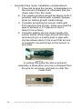
Installing BATT 55 UPG
Battery upgrades for base stations allow for longer running
time in severe weather conditions.
Note: Take consideration of the additional weight of the 55
Amp hour upgrade (60+ lbs), additional support or braces
may be needed.
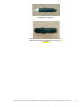
Illustration 34: Batt55 UPG Enclosure
Find a suitable location near the bottom of the pole to
mount the enclosure. Hint: it may be easier to mount the
enclosure with the battery removed, to do so simply
unscrew front cover and remove battery connectors being
sure to replace the cables to the original locations
blue=black(-) red=red(+).
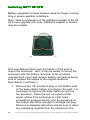
1. Remove the 1/2” knockout plug on the bottom side
of the base station before mounting to the pole, it is
necessary to remove the base station to remove
the knockout. Place the unit on a piece of flat
wood, a blow from a hammer to a flat head
screwdriver pressed directly onto the knockout on
the bottom should be enough to dislodge the plug.
Remove completely with pliers and be sure to clean
any remaining material from the entrance to the
42
© Ranch Systems LLC, 2005-2008. All Rights Reserved. Reproduction without permission from Ranch Systems is prohibited.
hole.
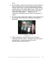
2. Route battery cable through pole by either drilling a
new hole (being sure not to drill through existing
sensor wires, etc), or pulling cable through nearest
existing hole in the base station pole. Remove nut
from liquid tight connector/strain relief, and feed
cable into base station. Replace nut on
connector and tighten well to ensure snug grip on
cable.
3. Connect wires inside base station box matching the
wire colors inside the box leading to the battery
terminals.
Illustration 35: Inside base station with battery
cables from batt55 connecting to inside
connectors.
4. After checking to ensure cables are correctly
matched with like cables. Reinsert the solar panel
plug into port 1 and ensure that the unit
synchronizes with the server.
© Ranch Systems LLC, 2005-2008. All Rights Reserved. Reproduction without permission from Ranch Systems is prohibited.
43
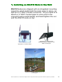
Installing Aquaspy Probes
AquaSpy Sensor is the most economical
solution for reading moisture at a single
depth.
AquaSpy Below Ground Probes come in
20, 40 and 60 inch lengths. The first
sensor is 2 inches below the top of the
probe. Sensors are spaced every 4
inches down the probe, which has 5, 10 and 15 sensors
respectively.
AquaSpy Above Ground Probes come in
40 and 60 inch lengths. The first sensor
is 4 inches below the bottom of the blue
cap. Sensors are spaced every 4 inches
down the probe, which has 10 and 15 sensors
respectively.
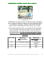
Installation Site Considerations
Where possible, soil type should be representative of the
general field conditions or site specific conditions which
represent the zone or plot as a whole. Plant type and
growth stage should be representative of this zone. The
probe is not installed where irrigation overlaps or at its
edge. Perform a site survey to confirm that the chosen
telemetry solution is effective at the installation site.
Select an installation site where the probe will be
44
© Ranch Systems LLC, 2005-2008. All Rights Reserved. Reproduction without permission from Ranch Systems is prohibited.
accessible but will not be subject to heavy traffic and has
adequate security. Install probes in the plant line and root
zone of representative plants, and between the irrigation
source and the reference plants.
For drip irrigation systems install the probe within the root
zone, typically 4 – 5 inches from the drip.
Slurry Installation: AquaSpy probes are installed into a
thick slurry mix. The slurry uses soil from the installation
site where possible. If that soil will not make thick slurry
Kaolin is recommended instead.
Filling gaps between the probe and soil, slurry is displaced
around the probe during probe installation.
Direct Installation: Because AquaSpy Soil Moisture
Probes contain precision electronics hitting a probe or cuts
in the cable void its warranty.
© Ranch Systems LLC, 2005-2008. All Rights Reserved. Reproduction without permission from Ranch Systems is prohibited.
45
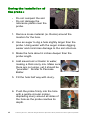
During the installation of
the probe :
•
•
Do not compact the soil.
Do not damage the
reference plants near the
probe.
1. Remove loose material (ie. Rocks) around the
location for the hole.
2. Use an auger to dig a hole slightly larger than the
probe. Using water with the auger makes digging
easier and minimizes damage to the soil structure.
3. Make the hole about 6 inches deeper than the
probe length.
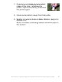
4. Add sieved soil or Kaolin to water,
making a thick slurry mix. Make sure
there are no lumps, yet it should be
“pourable”. Similar to Pancake
Batter.
5. Fill the hole half way with slurry.
6. Push the probe firmly into the hole
with a gentle circular motion,
displacing slurry around all sides of
the hole as the probe reaches its
depth.
46
© Ranch Systems LLC, 2005-2008. All Rights Reserved. Reproduction without permission from Ranch Systems is prohibited.
7. If slurry is not displaced around all
sides of the hole, withdraw the
probe, insert more slurry and install
the probe again.
8. Clear excess slurry away from the probe.
9. Neatly run wire to Node or Base Station, plug in to
RS485 Port.
Note: Consider protecting cables with PVC pipe to
the sensor.
© Ranch Systems LLC, 2005-2008. All Rights Reserved. Reproduction without permission from Ranch Systems is prohibited.
47
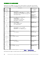
WIRING DIAGRAMS
Diagrams are for the Plugs on the end of wires, from the “inside” or “wiring side” of the connector.
This is also the same view of the Sockets mounted on devices as viewed from “outside” the device.
Pins on Plug
Description
(Cable end
Connector)
Manufacturer and
Part Number for
plugs
Solar Panel, AC Adapter.
Small Size for 1 Watt Supply, +V >= 12 VDC
Large Size for 10 Watt Supply, +V >= 14.4 VDC
Two GND Pins are connected in the plug to act
as the power switch
RM200 Series
SwitchCraft #
EN3C3F
Analog Sensor, Digital Counter, Digital BUS
+V = 5.0 VDC
Analog Signal = 0 – 5 VDC
Counter Signal = 5 VDC Pulse
BUS Signal = 1-Wire® Bus
Conxall #
16282-3PG-315
Wind Speed and Direction
+V = 5.0 VDC
Speed = Digital Counter
Dir = Analog Sensor
Conxall #
6282-5PG-3DC
Relays
Conxall #
16282-2SG-315
Power Output: 1 = +V ; 2 = GND
DC Latching : 1 = -V ; 2 = +V
Switch N.O. : 1,2 = Contact Closure
RS200 Series
Conxall #
16282-3SG-315
RS485 Serial
+V = 9.0 VDC
Conxall #
6282-4PG-3DC
RS232 Serial
+V = 9.0 VDC
Conxall #
6282-6SG-3DC
RS485/RS232 Serial
+V = 9.0 VDC
Conxall # 62828SG-3DC
Power Output
+V = 12.0 VDC
Conxall # 162822PG-315
Plugs can be ordered from RanchSystems, or online from Digikey or Allied Electronics.
Note that the last 3 digits of Conxall numbers refer to grommet size, which may be substituted.
48
© Ranch Systems LLC, 2005-2008. All Rights Reserved. Reproduction without permission from Ranch Systems is prohibited.
FURTHER HELP
This guide should have given you the tools needed to get
started, as well as an overview of the various features
available to you.
For detailed help and instructions on the various features,
please use the sidebar to access the desired feature, and
then scroll to the bottom of the web page, where you will
find additional instructions. Each time you click further
into the application, the bottom of the page will show the
relevant help information for that stage.
You can quickly identify the web page help texts by
looking for the context help icon:
However at Ranch Systems we completely understand
that you are likely to have questions and problems that go
beyond what we have anticipated in our help texts, and we
are always available to help you on the phone or by email:
Ranch Systems phone support: 415 884 2770.
Ranch Systems email support:
[email protected]
© Ranch Systems LLC, 2005-2008. All Rights Reserved. Reproduction without permission from Ranch Systems is prohibited.
49
Alphabetical Index
Email............................................................................................................................................5, 13, 49
Help...................................................................................................................................................5, 49
Mesh Node........................................................................................................................................6, 15
Relay...........................................................................................................................................6, 19, 48
RM210.....................................................................................................................................................6
RS100......................................................................................................................................................6
RS210......................................................................................................................................................6
RS232..............................................................................................................................................19, 48
RS485..............................................................................................................................................19, 48
RSRF Node.......................................................................................................................................6, 15
Solar panel................................................................................................................................10, 20, 22
Support....................................................................................................................................................5
User Manual............................................................................................................................................5
Illustration Index
Illustration 1: Weather Station mounted to 35' Telespar Antenna Mast................................................8
Illustration 2: Standard Weather Station Installed on 10' x3” ABS Pipe................................................8
Illustration 3: RM210 Mainboard layout with alternate modem configurations....................................11
Illustration 4: Typical Base Station mounting on 3” ABS drain pipe....................................................16
Illustration 5: Base station with Antenna extension mounted on 30' Telespar Mast...........................17
Illustration 6: Drilling base station pole with hole locations marked on 3/4” PVC................................18
Illustration 7: Base Station Connectors................................................................................................19
Illustration 8: Solar Panel Assembly.....................................................................................................20
Illustration 9: Nut and Screw Installation..............................................................................................21
Illustration 10: Nut and Screw Installation............................................................................................21
Illustration 11: Nut and Screw Installation............................................................................................21
Illustration 12: Assembled Solar Panel, (exposure side facing down).................................................22
Illustration 13: Attach bolts and mounting bracket...............................................................................23
Illustration 14: Bolt and spacer installation on Radiation Shield..........................................................23
Illustration 15: Screw pattern for underside of .....................................................................................24
Illustration 16: Be sure cable is not pinched when securing bucket to bracket...................................25
Illustration 17: Bird Spike Kit.................................................................................................................26
Illustration 18: The mark on the spindle or wind direction axle will align with the armature................27
Illustration 19: Installation on a 3/4” EMT Conduit for an RS-210......................................................28
Illustration 20: RS-210 Micro-climate Weather Station........................................................................29
Illustration 21: RS210 Node..................................................................................................................31
Illustration 22: RS210 Deployed on 10' Conduit pipe...........................................................................31
Illustration 23: RS210 Node Assembly ready to deploy on 3/4” EMT Conduit pipe............................31
Illustration 24: RS100 Sensor Node Assembly....................................................................................32
Illustration 25: RS100 Deployed on 10' PVC pipe................................................................................32
Illustration 26: RS100 Node..................................................................................................................33
Illustration 27: RS210 Node..................................................................................................................33
Illustration 28: Pyranometer Assembly.................................................................................................38
Illustration 29: Irrigation Monitoring with inline rotary flowmeter and Aquaspy soil moisture sensor.39
Illustration 30: Flowmeter with locking poly tube fitting........................................................................41
Illustration 31: Flow meter poly tube installation kit; Assembly exploded view...................................41
Illustration 32: Flow meter poly tube installation kit; Assembled..........................................................41
Illustration 33: Flow meter barb fitting installation kit, requires hose clamps or otherwise to secure
pipe, .375Z' O.D...................................................................................................................................41
Illustration 34: Batt55 UPG Enclosure..................................................................................................42
Illustration 35: Inside base station with battery cables from batt55 connecting to inside connectors.43
50
© Ranch Systems LLC, 2005-2008. All Rights Reserved. Reproduction without permission from Ranch Systems is prohibited.
© Ranch Systems LLC, 2005-2008. All Rights Reserved. Reproduction without permission from Ranch Systems is prohibited.
51