1
PSZ 19:16 (Pind. 1/07)
UNIVERSITI TEKNOLOGI MALAYSIA
DECLARATION OF THESIS / UNDERGRADUATE PROJECT PAPER AND COPYRIGHT
Author’s full name
:
MUHAMMAD AKMAL BIN MOHAMAD ROSLAN
Date of birth
:
27 DECEMBER 1988
Title
:
WIRELESS FORKLIFT WITH OMNIDIRECTIONAL
MOVEMENT
Academic Session:
2010/2011
I declare that this thesis is classified as:
CONFIDENTIAL
(Contains confidential information under the Official Secret
Act 1972)*
RESTRICTED
(Contains restricted information as specified by the
organisation where research was done)*
OPEN ACCESS
I agree that my thesis to be published as online open access
(full text)
I acknowledged that Universiti Teknologi Malaysia reserves the right as follows :
1. The thesis is the property of Universiti Teknologi Malaysia.
2. The Library of Universiti Teknologi Malaysia has the right to make copies for the purpose
of research only.
3. The Library has the right to make copies of the thesis for academic exchange.
Certified by :
SIGNATURE
881227-56-6125
(NEW IC NO. /PASSPORT NO.)
Date : 16 MAY 2011
NOTES :
*
SIGNATURE OF SUPERVISOR
MOHD ARIFFANAN BIN MOHD BASRI
NAME OF SUPERVISOR
Date : 16 MAY 2011
If the thesis is CONFIDENTIAL or RESTRICTED, please attach with the letter from
the organisation with period and reasons for confidentiality or restriction.
i
“I hereby declare that I have read thesis and in my opinion this thesis is
sufficient in terms of scope and quality for the award of the degree of
Bachelor of Engineering (Electrical - Mechatronics)”
Signature
:
………………………………………………
Name of Supervisor :
MOHD ARIFFANAN BIN MOHD BASRI
Date
16 MAY 2011
:
WIRELESS FORKLIFT WITH OMNI-DIRECTIONAL MOVEMENT
MUHAMMAD AKMAL BIN MOHAMAD ROSLAN
A thesis submitted in partial fulfillment of the requirements for the award of the
degree of Bachelor of Engineering (Electrical - Mechatronics)
Faculty of Electrical Engineering
Universiti Teknologi Malaysia
MAY 2011
ii
“I hereby declare that this thesis entitled “Wireless Forklift with Omni-Directional
Movement” is the result of my own research except as cited in the references. The
thesis has not been accepted for any degree and is not concurrently submitted in
candidature of any other degree.
Signature
:
………………………………………………………….
Name of Candidate
:
MUHAMMAD AKMAL BIN MOHAMAD ROSLAN
Date
:
16 MAY 2011
iii
ACKNOWLEDGEMENTS
Alhamdulilah, I finally complete and finish my final year project
successfully. It helps me so much in understanding my previous lectures. Experience
that I obtain from doing my final year project shall prove to be an asset in the pursuit
of my studies as well as for my future career prospects.
First and foremost, I would like to praise to Allah S.W.T for giving me a little
strength and ability to done my final year project successfully, Alhamdulillah. I
would like to take this opportunity to thank to my supervisor, Mr. Mohd Ariffanan
Bin Mohd Basri for his supervision, guidance and support throughout this project.
Besides that I would like to record my gratitude to my beloved parents
because without them, I will not be able to do well in my final year project. They did
give me a lot of support, both from money and moral support to help me continue for
what I had started on.
Last but not least, I would like to appreciate to my colleagues and others who
provided assistance at various occasions involved either directly or indirectly in
completing this project. Their views and tips are useful indeed. May Allah S.W.T
bless for the cooperation and support.
iv
ABSTRACT
Forklift is powered industrial truck used to lift and transport materials.
Forklift has become indispensable equipment in manufacturing and warehousing
operations. This project was implemented a mobile robot concept to the forklift. The
mainly is about designing and fabricating forklift which is can move in
omnidirectional movements and operated by PS2 wireless controller. This forklift
can move freely in ten movements. PIC16f777 was act as a brain for this forklift to
produce the output signal to control the forklift movements. Three transwheel was
been used to make this forklift can move in omnidirectional movements and one
servo motor to lift up and down the light object. To make it can control using PS2
wireless controller is by using SKPS module that can receive data from PS2 wireless
controller and transmit to PIC16f777. This research has a great functions and benefits
and can be proceed in the future.
v
ABSTRAK
Forklift merupakan salah satu trak industri berkuasa yang digunakan untuk
mengangkat dan menyusun barang. Kini forklift telah dianggap sebagai peralatan
yang amat penting untuk operasi di gudang dan kilang. Dalam projek ini, konsep
robot mudahalih telah dilaksanakan pada forklift. Tujuan rekabentuk model robot ini
adalah untuk membolehkan forklift bergerak “omnidirectional” dan kawal dengan
menggunakan “PS2 wireless controller”. Forklift ini boleh bergerak dengan sepuluh
arah. PIC 16f777 bertindak sebagai otak yang memproses maklumat dan member
isyarat keluaran untuk mengawal operasi motor. Tiga “transwheel” tayar digunakan
untuk membolehkan forklift bergerak “omnidirectional” dan satu servo motor untuk
mengangkat dan menurunkan objek yang ringan. Modul SKPS digunakan untuk
menerima maklumat dari “PS2 wireless controller” dan menghantar maklumat
tersebut kepada PIC16f777 untuk diproses. Penyelidikan dalam bidang ini
mempunyai fungsi yang hebat dan kebaikan serta dapat dilanjutkan di masa hadapan.
vi
TABLE OF CONTENTS
CHAPTER
TITLE
PAGE
DECLARATION
ACKNOWLEGEMENTS
ABSTRACT
ABSTRAK
TABLE OF CONTENT
LIST OF FIGURES
LIST OF TABLES
LIST OF ABBREVIATIONS
LIST OF APPENDIX
ii
iii
iv
v
vi
viii
ix
x
x
1
INTRODUCTION
1.1
Project Background
1.2
Problem Statement
1.3
Objective of Project
1.4
Scope of Project
1.5
Outline of Thesis
1.6
Summary of Works
1
1
2
2
2
3
3
2
LITERATURE REVIEW
2.1
Introduction
2.2
Wireless Forklift by Abdul Aziz
2.3
Unmanned Autonomous Forklift
2.4
Cooperation Multi Agent Soccer Robot Team
2.5
Flexibot-Using Transwheel
ATX-Series Omni-Directional
2.6
Forklift
5
5
6
7
8
9
3
METHODOLOGY
3.1
Introduction
Mechanical
3.2
Design
3.2.1
DC Geared
10
12
12
13
16
vii
3.3
3.4
3.5
Motor
3.2.2
RC Servo Motor
3.2.3
Transwheels
Electronic and Circuit Design
3.3.1
Power Supply Circuit
3.3.2
Lipo Battery
3.3.3
I/O Pin Assignation of PIC16f777
L298 Motor
3.3.4
Driver
3.3.5
PS2 Controller Starter Kit
3.3.6
PS2 Wireless Controller
Programming Design
Summary of Chapter 3
17
20
21
21
23
24
26
29
31
32
37
4
RESULT AND DISCUSSION
4.1
Introduction
4.2
Final Hardware Design
4.3
The Movement of Omni-Directional Movement
4.4
Movement of Pick and Place Light Object
4.5
Discussions
39
39
39
41
43
44
5
CONCLUSION AND RECOMMENDATIONS
5.1
Conclusion
5.2
Recommendation
45
45
46
REFERENCES
APPENDIX
47
48
viii
LIST OF FIGURES
FIGURE
2.1
2.2
2.3
2.4
2.5
3.1
3.2
3.3
3.4
3.5
3.6
3.7
3.8
3.9
3.1
3.11
3.12
3.13
3.14
3.15
3.16
3.17
3.18
3.19
3.2
3.21
3.22
3.23
3.24
3.25
TITLE
Wireless Forklift By Abdul Aziz
Clark CRX-10 forklift equipped with sensors
Right side is 3-wheel robot and left side is 4-wheel robot
Flexibot-Using Transwheel
Airtrax ATX-3000 Forklift
Step taking in developing wireless
forklift
with omni-directional movement
Base design
Fork arm design
Complete mechanical design of forklift
Dimension of base design
The base
DC Geared Motor MO-SPG-30-20K
Dimension of RC Servo Motor C55R
RC Servo Motor C55R
Specification of Servo Motor
Signal of Pulse Servo Motor
Rotation of Servo Regarding The Pulse Given
Transwheels
Voltage regulator circuit with 5 volt output
Voltage regulator circuit with 6 volt output
Main Circuit
11.1 Lipo Battery
Dual-In line type PIC16F777
Pin Diagram of PIC16F777
Left side is the pin diagram and right
side
is picture of L298 motor
driver
Circuit Design of L298 Motor Driver
Motor Circuit Driver
SKPS PS2 Controller Starter Kit
PS2 Wireless Controller with receiver
MPLAB IDE compiler interface
PAGE
6
7
8
10
11
13
14
14
14
15
15
16
17
18
18
19
20
21
22
22
23
24
25
25
29
28
28
30
31
32
ix
3.26
3.27
3.28
3.29
4.1
4.2
4.3
4.4
PICkit2 Programmer Interface
USB ICSP PIC Programmer
Software Programming Design Flow Chart
Flow Chart of Wireless Forklift with Omni-directional
Movement Programming
Different view of Wireless Forklift with Omni-directional Movement
Wireless Forklift at Early Stage
Direction of the forklift by using transwheel
Flow of Wireless Forklift to Lift Up a Light
Object
33
34
35
36
40
41
42
43
LIST OF TABLES
TABLE
TITLE
PAGE
1.1
Gantt chart FYP 1
4
1.2
Gantt chart FYP 2
4
3.1
PIC16F777 Device Features
26
3.2
Pin Function of Chip L298
27
3.2
SKPS PS2 Controller Starter Kit Function Description
30
x
LIST OF ABBREVIATIONS
DC
-
Direct Current
RC
-
Radio-Controlled
PIC
-
Programmable Interface Controller
PS2
-
Play Station 2
RM
-
Ringgit Malaysia
TTL
-
Transistor-transistor Logic
ICSP
-
In-Circuit Serial Programming
USB
-
Universal Serial Bus
UART
-
Universal Asynchronous Receiver/Transmitter
Li-Po
-
Lithium Polymer
W
-
Watts
V
-
Voltage
A
-
Ampere
kg
-
kilograms
cm
-
centimeter
s
-
Second
ms
-
millisecond
g
-
Gram
LIST OF APPENDIX
TITLE
APPENDIX
A
Source Code
PAGE
48
1
CHAPTER 1
INTRODUCTION
1.1
PROJECT BACKGROUND
Nowadays, forklifts have become an alternative in term to move loads from
one place to another place. For instance forklift is widely being used in
manufacturing industry. Forklift will make our work more efficiency and easier.
Omni-directional wheels have become popular for mobile robots because
these wheels allow the mobile robot to drive on a straight path from a given location
on the floor to another without any rotation needed by the mobile robot. Moreover,
the mobile robot can arrive to its destination at the correct angle with combination of
the rotation of these wheels.
In this project, the mobile robots that will be built are implementing using
these two concepts. Forklift will be implementing with transwheels so it can move
load in omni-directional movement and will be controlled using wireless joystick.
The title of this project is wireless forklift with omni-directional movement.
2
1.2
PROBLEM STATEMENT
Most of forklift that use in manufacturing industry can only move forward
and reverse, so it will have a problem to move a load when the forklift enter a narrow
space. It also will take a time when the driver wants to adjust the forklift to go to the
desired place. Therefore, this wireless forklift with omni-directional movement is
designed to resolve this problem.
1.3
OBJECTIVE OF PROJECT
This project is carried out three objectives, the first objective of this project is
to design and build a forklift that can lift-up and lift-down a load and carry the light
object. This project is fabricated by applying the concepts and characteristics of the
real forklift. The second objective is to make this forklift can move to all direction
without rotate the wheels. The last objective is to design an operating system for
forklift so this forklift can be control using wireless joystick.
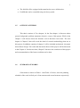
1.4
SCOPE OF PROJECT
The scopes that states below is the guidelines that listed to ensure the project
is conducted within its boundary of mechanical hardware, circuit design, and
software design. This is to ensure that the objective of this project will achieve.
•
Design mechanical and electronic hardware that will suit with software that
will do developed.
•
Using one servo motor to lift-up and lift-down a light object.
3
1.5
•
The forklift will be equipped with transwheels to move all direction.
•
Forklift that can be controlled using wireless joystick.
OUTLINE OF THESIS
This thesis consists of five chapters. In the first chapter, it discusses about
project background, problem statement, objective, scope of this project. While in the
Chapter 2 will discuss about the literature review that have been done. The next
chapter is Chapter 3 that will reveal the detail of research methodology that use in
this project. In addition contains of chapter 3 will be included mechanical, electronic
and software design. The result and discussion about of this project will be discussed
in the Chapter 4. Last but not least, Chapter 5 discusses the conclusion of this project
and recommendation of the future work that can be done.
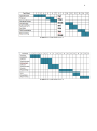
1.6
SUMMARY OF WORKS
Gantt charts as shown in Table 1.1 and Table 1.2 below, show the planning
schedule of the work in final year’s first semester and second semester respectively.
4
Table 1.1: Gantt chart FYP 1
Table 1.2: Gantt chart FYP 2
5
CHAPTER 2
LITERATURE REVIEWS
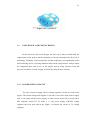
2.1
INTRODUCTION
This chapter are reviewing the similar project according to my project. This
similar project will be my guideline to this project. Literature review of this project
are divided into two parts, first part is about forklift and the other part about omnidirectional robot. This chapter is important because this is my reference to start and
during I doing this project.
6
2.2
WIRELESS FORKLIFT BY ABDUL AZIZ
A wireless forklift was built by Abdul Aziz Bin Abdul Rahman in his
undergraduate project in year 2010. Figure 2.1 below shows the picture of wireless
forklift.
Figure 2.1: Wireless forklift By Abdul Aziz
This wireless forklift consist Tamiya Twin-Motor Gearbox DC Motor, one
Hextronix HX5010 Servo Motor, and Bluetooth Module. This forklift use Tamiya
Twin-Motor DC Motor to move forward and backward, and to lift-up the load,
Hextronix HX5010 Servo Motor are been used. Microcontroller that been use as the
brain to this forklift is PF16f877A. This wireless forklift are capable to move
forward, backward, turn right and left by controlling using laptop, the Bluetooth
Module will connect with laptop and receive a command from the laptop and will
give the information to the microcontroller. The weight of load that this wireless
forklift can lift-up is around 100 grams and dimensions of 6 x 7 x 11 cm.
7
2.3
UNMANNED AUTONOMOUS FORKLIFT
This unmanned autonomous forklift is a standard industrial forklift that
produced by the CLARK Company and name as CRX-10. The CRX-10 forklift is
shows in Figure 2.2.
Figure 2.2: Clark CRX-10 forklift equipped with sensors
This unmanned forklift are mounted with four wheels include one small
caster wheel at the right rear side and two caster wheel at the front side, and one
main wheel at the left rear side for controlling the direction of the forklift. These
forklifts have ability for dual operations that is unmanned mode and manual mode.
For unmanned mode, order motions are generated based on information provided by
some sensor pose.
8
2.4
COOPERATIVE MULTI AGENT SOCCER ROBOT TEAM
This robot has been designed to enter a RoboCup mobile robot competition
and the objectives of this competition are a robot must be prepared to accelerate in an
appropriate direction, recognize ball and the others robot swiftly, can kick ball with
sufficient velocity, and with proper accuracy. To achieve the characteristics of this
robot, two type of multi agent soccer robot team have been design which is threewheel triangle robot and four-wheel Cartesian robot that are shows in Figure 2.3.
According to the different maneuvers of the two robots, a team from both types of
robot can have more flexibility and powerful mobility.
Figure 2.3: Right side is 3-wheel robot and left side is 4-wheel robot
Three 80 W DC servomotors are used on three-wheel triangle robot. Based on
the physical characteristic robot, the maximum speed acceleration is 2m/sec and
3m/sec2 appropriate. Robot with three-wheel mechanism is quite faster and more
flexible in order to reach the ball and the desire orientation. To kick the ball, spring
that capable of compressing and releasing has implemented.
9
Second type of robot is consists four omniwheels and rotational kicker part.
Each omniwheels are supported with one DC servo motor that can make the robot
move. The movement of this robot is according from the result of the comparative
generating motors, thus each pair of wheels will force robot to move. And for the
system kicks, on top of this robot can turn 360 degrees that can enables the robot to
optimize the way to reach the ball with necessary orientation for the right kick. This
will saves time and also simplify the rotation of the robot control algorithm, which is
a significant advantage of this robot.
2.5
FLEXIBOT-USING TRANSWHEEL
The Flexibot is a three transwheels mobile robot which is allows Flexibot to
move in any direction without having turn relative to the robot base. For example to
move sideways, normal mobile robots need to turn 90 degrees, move forward, and
then turn back to its original direction. But using this Flexibot, it can execute a single
sideways motion, and further can easily track a moving oject while maintaining a
required orientation with respect to it. This Flexibot is an autonomous robot, it have a
push button to select the mode of movement of the Flexibot. Furthermore this
Flexibot have LCD display to display the current mode and the situation. The Figure
2.4 below shows the picture of Flexibot-Using Transwheel.
10
Figure 2.4: Flexibot-Using Transwheel
2.6
ATX–SERIES OMNI-DIRECTIONAL FORKLIFT
Airtrax ATX-3000 Industrial forklifts excel in applications requiring tight
maneuvering or transporting long roads sideways. The ATS’s unique, OmniDirectional movement allows it to travel in all directions thus making it an ideal
vehicle to work in tight spaces where turns are not possible and finite control is a
must. The truck feature 48 volt transistor controls with state of the art technology,
infinitely variable travel, lift and lower speeds, excellent visibility, ergonomic
controls and operator comfort. The Figure 2.5 below shows the picture of the ATXSeries Omni-Directional Forklift.
11
Figure 2.5: Airtrax ATX-3000 Forklift
12
CHAPTER 3
METHODOLOGY
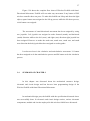
3.1
INTRODUCTION
This chapter will discuss about process in designing robot. This project is
divided into two parts, hardware design and software design. This project must be
done step by step follow the flow such as shows in Figure 3.1 in order to achieve the
objective of the project.
Idea and the concept to do this project is was inspired by the unique of
transwheel that can move in all direction by controlling the speed of motor, and to
make it the forklift can do the work in a narrow space environment.
In the beginning of this project, various sources have been collected such as
journals, past year thesis from library utm and internet.
13
1
2
• Idea and Concept
• Literature Review and Research
3
• Mechanical Design and Construction
4
• Circuit Design and Making
5
• Software Programming
6
• Hardware and Software Integration
7
• Testing and Implementation
8
• FinishingProject
Figure 3.1: Step taking in developing wireless forklift with omni-directional
movement
3.2
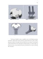
MECHANICAL STRUCTURE DESIGN
The mechanical design of the base and the fork arm of wireless forklift with
omni-directional movement was design using SolidWorks. Figure 3.2 and Figure 3.3
below shows the design of the base and fork of the forklift. Figure 3.4 shows the
combination of base and the fork arm.
14
Figure 3.2: Base design
Figure 3.3: Fork arm design
Figure 3.4: Complete mechanical design of forklift
The design of forklift is to have a capability to move in all direction smoothly
and can do a simple task to lift-up an object by using its fork arm. In order to achieve
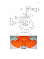
that target, design of the mobile robot and forklift has been studied. The dimension
of the base that will be used in this project is shown in Figure 3.5. And in Figure 3.6
shows the picture of base that has been done and the material was used to build the
base is prospect.
15
Figure 3.5: Dimension of base design
Figure 3.6: The base
16
3.2.1
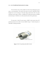
DC GEARED MOTORS (MO-SPG-30-20k)
The locomotion of the wireless forklift was achieved by utilizing DC geared
motor to each transwheels. The model of the motor was used is MO-SPG-30-20K,
bought from Cytron Technologies. The rated voltage of this motor is DC 12V and it
maximum current rating is 300mA. An addition, the flexible rated speed at 185 RPM
and rated torque at 78.4mN.m were offered by this model of DC geared motor.
The unit price of this DC geared motor is RM70. In this project, three DC
geared motor have been use thus it costs me RM210. Figure 3.7 shows the picture of
a MO-SPG-30-20K geared motor.
Figure 3.7: DC Geared Motor MO-SPG-30-20K
17
3.2.2
RC SERVO MOTOR (C55R)
Servos are controlled by sending them a pulse of variable width. The signal
wire is used to send this pulse. Inside a typical RC servo contains a small motor and
gearbox to do the work, a potentiometer to measure the position of the output gear,
and an electronic circuit that controls the motor to make the output gear move to the
desired position. Because all of these components are packaged into a compact, lowcost unit, RC servos are great actuator for robots.
C55R RC Servo Motor is designed for closed feedback control. The pulse
width range of this servo is from 0.5ms – 2.5ms. The dimension and picture of C55R
servo motor are shows in Figure 3.8 and 3.9. The weight of this servo motor is 55g
and the gear material that provide in this motor is metal gear. Furthermore, the speed
and torque of this servo motor can reach are 0.22(s/600) speed and 9.00(Kg.cm) for
4.8V operation, 0.20(s/600) speed and 11.00(Kg.cm) torque for 6.0V operation and
last but not least 0.17(s/600) speed and 13.00(Kg.cm) torque for 7.0V operation.
Figure 3.10 shows the specification on servo motor. One C55R servo motor has
bought from Cytron Technologies that costs me RM 80.
Figure 3.8: Dimension of RC Servo Motor C55R
18
Figure 3.9: RC Servo Motor C55R
Figure 3.10: Specification of Servo Motor
19
Servos are controlled by sending them a pulse of variable width. Pulse Width
Modulation is the pulse that applied to servo motor to determine the angle of servo
motor. The complete cycle for servo is 20ms, Figure 3.11 shows the square wave
signal of servo motor. How far the motor turns was determined by the length of the
pulse. An example, if a 1.5ms pulse sends to servo, it will make the motor turn to the
90 degree position (neutral position).
Figure 3.11: Signal of Pulse Servo Motor
The position pulse must be repeated to make the servo stay in that position.
The servo will rotate anticlockwise if the pulse sent to servo is less than 1.5ms.
Hence to make servo rotate clockwise, the pulse that sent to servo must be higher
than 1.5ms. However there is a minimum and maximum pulse that can send to servo
otherwise servo motor will be damaged. The minimum pulse can be sent is 1ms and
the maximum pulse is 2.5ms. Figure 3.12 shows the rotation of servo for the pulse
given.
20
Figure 3.12: Rotation of Servo Regarding The Pulse Given
3.2.3
TRANSWHEEL
Three transwheels were used and attached to the base of the forklift and the
DC geared motor. Transwheel is unique wheel, it can make mobile robot moving in
all direction by controlling the speed of the DC motor. Transwheel are place in
sequence 1200 around the base. Each transwheel are attached to the coupling before
attached to the DC geared motor. Transwheel and coupling also have been bought
from Cytron Technologies with RM70 per unit and RM20 per unit. In my project, I
use three transwheels so it costs me RM210 for this wheel and RM60 the coupling.
Figure 3.13 shows the picture of the transwheels.
21
Figure 3.13: Transwheels
3.3
ELECTRONIC AND CIRCUIT DESIGN
In the electronic and circuit design, the first step is must to understand the
requirements of the project and the limitation of various constraints like the level of
technology, reliability of microcontroller and the complexity of programming codes
and interfacing devise. By using datasheet that search using internet, analyze about
the component that want to use in the project and by using reference from the
previous researcher. Circuit designs are drawn by using Proteus software.
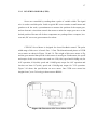
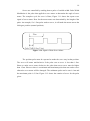
3.3.1
POWER SUPPLY CIRCUIT
Two type of power supply circuit (voltage regulator circuit) are used in this
project. The output voltage that supplies 5 volt and 6 volt will be used. Power supply
with 5 volt output will be used to supply on main circuit, motor driver circuit and to
PS2 controller starter kit. To make a +5 volt power supply, LM7805 voltage
regulator has been used and in the Figure 3.14 shows the circuit of 5V voltage
regulator.
22
Figure 3.14: Voltage regulator circuit with 5 volt output
Another power supply is 6 volt output voltage regulator. To make it can
produce +6 volt, LM7806 voltage regulator has been used and Figure 3.15 shows the
circuit design of 6 volt voltage regulator. Figure 3.16 shows the main circuit that
consist PIC circuit and 5 volt and 6 volt voltage regulator that has been built.
Figure 3.15: Voltage regulator circuit with 6 volt output
23
Figure 3.16: Main Circuit
Power supply that used to supply the voltage regulator circuit is Lipo battery
11.1 volt DC. Sometimes the input supply may be noisy. To overcome this problem
and to get a better 5 volt and 6 volt output, capacitor is added to the circuit.
3.3.2
LIPO BATTERY
Lithium Polymer or Lipo battery is a type of rechargeable battery. In this
project, I use two 11.1V Lipo batteries. One of battery is used for two DC geared
motor and another one is used to one DC geared motor and to both voltage regular to
supply power to circuit. Figure 3.17 shows the picture of Lipo battery.
24
Figure 3.17: 11.1 Lipo Battery
3.3.3
I/O PIN ASSIGNATION OF PIC16F777
Microcontroller is used in this project because of its small size, low cost but
high performance. Microcontrollers is combination microprocessor, memory, I/O
ports and other special function registers such as timer, ADC, PWM and interrupt.
PIC16F777 was selected as microcontroller that will be used in this project.
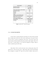
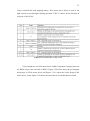
Figure 3.18 shows the picture of PIC16F777, Figure 3.19 pin diagram of PIC16F777
and Table 3.1 shows the features of this microcontroller.
25
Figure 3.18: Dual-In line type PIC16F777
Figure 3.19: Pin Diagram of PIC16F777
26
Table 3.1: PIC16F777 Device Features
3.3.4
L298 MOTOR DRIVER
If a DC motor is connected directly to the battery, DC motor will be provided
with a constant power all the time. Due to this constant power, the speed of motor
will slow down or speed up regarding the load it takes. If the load is heavier the
speed of motor will be slow down and speed up when the load is lighter. Hence, DC
motor driver is needed which is it can control the magnitude of supply voltage in
order to control the speed of DC motor.
Motor Driver L298 is used in the main circuit as driving chip of three DC
geared motors. This motor driver gives a high voltage, high current dual full-bridge
driver designed to accepted TTL logic levels and drive inductive loads such as
27
relays, solenoids DC and stepping motors. This motor driver allows a total of 4A
high current to pass through it during operation. Table 3.2 below shows function of
each pin of chip L298.
Table 3.2: Pin Function of Chip L298
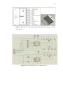
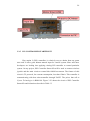
I have bought two of L298 motor driver at RS Component Company that cost
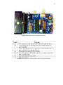
me RM16.50 per unit and total is RM33. Figure 3.20 below show the pin diagram
and picture of L298 motor driver and Figure 3.21 is show the circuit design L298
motor driver. In the Figure 3.22 shows the motor driver circuit that has been built.
28
Figure 3.20: Left side is the pin diagram and right side is picture of L298
motor driver
Figure 3.21: Circuit Design of L298 Motor Driver
29
Figure 3.22: Motor Circuit Driver
3.3.5
PS2 CONTROLLER STARTER KIT
Play station 2 (PS2) controllers is relatively easy to obtain from any game
store and it offers good human manual input for control system. More and more
developers are looking into applying existing PS2 controller to control particular
system. On my project, PS2 Controller Starter Kit will be used to connect wireless
joystick and the main circuit to control this forklift movement. The feature of this
circuit is 5V powered, low current consumption, less than 150mA. This controller is
communicating with host microcontroller through UART. The prices that sell at
Cytron Technologies is RM99.90. Figure 3.23 shows the circuit of PS2 Controller
Starter Kit and it functions describe in Table 3.3
30
Figure 3.23: SKPS PS2 Controller Starter Kit
Table 3.3: SKPS PS2 Controller Starter Kit Function Description
31
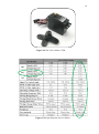
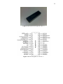
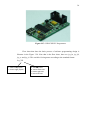
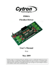
3.3.6
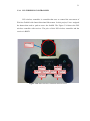
PS2 WIRELESS CONTROLLER
PS2 wireless controller is controller that uses to control the movement of
Wireless Forklift with Omni-directional Movement. In this project, I have assigned
the button that need to push to move the forklift. The Figure 3.24 shows the PS2
wireless controller with receiver. The price of this PS2 wireless controller and the
receiver is RM70.
Receiver
Joy_lu
Joy_ll
Joy_ru
Joy_lr
Joy_ld
Joy_rl
Joy_rr
Joy_rd
Figure 3.24: PS2 Wireless Controller with receiver.
32
3.4
PROGRAMMING DESIGN
After finishing mechanical and electronic circuit part, the attention has been
shift to the programming development. There are two type of software were used in
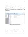
this project which is MPLAB IDE to write a program and convert to the hex file that
the language that PIC microcontroller use and the other one is PICkit2 is to load the
hex file into the PIC microcontroller. Figure 3.25 illustrate the MPLAB IDE
compiler interface.
Figure 3.25: MPLAB IDE compiler interface
C-language is chosen as the programming language for this project due to the
memory size of C-language is small and easy to understand. MPLAB IDE software
that use in this project was employed to write the C-language programming. USB
ICSP PIC programmer is use together with PICkit2 software to load the hex file into
33
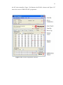
the PIC microcontroller. Figure 3.26 illustrate, the PICkit2 software and Figure 3.27
shows the circuit of USB ICSP PIC programmer.
Figure 3.26: PICkit2 Programmer Interface
34
Figure 3.27: USB ICSP PIC Programmer.
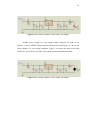
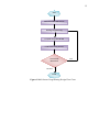
Flow chart that show the basic process of software programming design is
illustrate in the Figure 3.28. Note that in the flow chart, there are joy_lu, joy_ld,
joy_rr and joy_rl. This variable is being name according to the standard format.
Joy_XX
‘l’ means left joystick
‘r’ means right joystick
‘u’ means up-axis
‘d’ means down-axis
‘r’ means right-axis
‘l’ means left-axis
35
Start
Desired Forklift Movement
Writing Programming
Compile Using MPLAB IDE
Load to PIC Using PICkit2
Test Forklift
Movement
Fail
Success
Finish
Figure 3.28: Software Programming Design Flow Chart
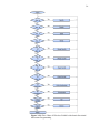
36
Figure 3.29: Flow Chart of Wireless Forklift with Omni-directional
Movement Programming
37
Figure 3.29 shows the complete flow chart of Wireless Forklift with OmniDirectional Movement. Forklift will not make any movement if any button of PS2
wireless controller does not press. To make this forklift can lift up and down the light
object; square button was assigned to the lift up process while the lift down process,
circle button was assigned.
The movement of omni-directional movement has been assigned by using
two joysticks. Left joystick was assigned to make forward (north), and backward
(south) direction while to the left (west), and right (east) direction right joystick has
been assigned. However to make the north east, north west, south east, and south
west direction the both joystick has been assigned to used together.
Last but not least is the clockwise and anticlockwise movement. L1 button
has been assigned to do the anticlockwise process and R1 button to do the clockwise
process.
3.4
SUMMARY OF CHAPTER 3
In this chapter was discussed about the mechanical structure design,
electronic and circuit design and last but not least programming design of the
Wireless Forklift with Omni-Directional Movement.
In mechanical design part, the forklift with the specification discussed above
was successfully done. In electronic and circuit design section, various electronic
components, module and circuits employed in this wireless forklift were discussed.
38
Furthermore in the programming part, the selection for software to do
programming was determined and flow chart for the movement of Wireless Forklift
with Omni-Directional Movement was discussed.
39
CHAPTER 4
RESULT AND DISCUSSION
4.1
INTRODUCTION
The result of Wireless Forklift with Omni-directional Movement shall be
explained in this chapter. This chapter also discusses about the problems that are
encountered throughout the completion of this project. This project has been
executed step by step. The first step that been executed is to make this project can
move in the omni-directional movement. After this objective have achieved, the
second step is to control this project using PS2 wireless controller and finally is to lift
up and carry the light object.
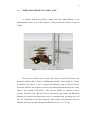
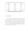
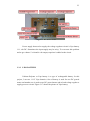
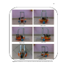
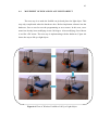
4.2
FINAL HARDWARE DESIGN
The final hardware design of Wireless Forklift with Omni-directional
Movement is illustrated in Figure 4.1
40
Front view
Back view
Right view
Left view
Plan view
Isometric view
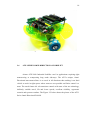
Figure4.1: Different view of Wireless Forklift with Omni-directional Movement
41
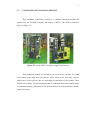
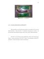
4.3
THE MOVEMENT OF OMNI-DIRECTIONAL MOVEMENT
The first step is to make this project can move in the omni-directional
movement. To do this, first we need to check connectivity of the circuit before try
simple programming to this project which is to make this project clockwise and anti
clockwise. After simple programming has succeeded, the programming of ten
movements is implementing to this project.
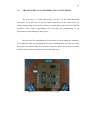
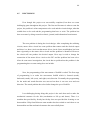
However the first programming of movement is not including the controller,
it is automated. After the programming has been confirmed, then next step is to make
this project can control using PS2 controller. Figure 4.2 shows the picture of wireless
forklift with omni-directional movement at this stage step.
Figure4.2: Wireless Forklift at Early Stage
42
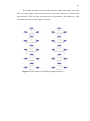
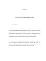
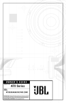
The forklift was able to move north (forward), south (backward), west (turn
left), east (turn right), north east, north west, south east, south west, clockwise and
anticlockwise. Total all of the movement are ten movements. The directions of the
movement are shown on the Figure 4.3 below.
Figure 4.3: Direction of the forklift by using transwheel
43
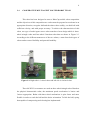
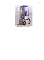
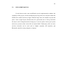
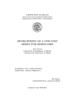
4.4
MOVEMENT OF PICK AND PLACE LIGHT OBJECT
The next step is to make the forklift can pick and place the light object. This
step only complicated when the hardware does. Before implement software into the
hardware, first we need to test the programming at servo motor. In this case, servo
motor has already been modifying to turn 360 degree. After modifying, Servo Motor
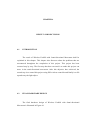
is act like a DC motor. The next step is implementing with the hardware, Figure 4.4
shows the step to lift up a light object.
Figure4.4: Flow of Wireless Forklift to Lift Up a Light Object
44
4.5
DISCUSSIONS
Even though this project was successfully completed, but there are some
challenging parts throughout this project. The first and foremost is when to start the
project, the problem is what components to be used and the circuits design, what the
suitable base to be used and the programming that have to write. The problem has
been overcome by doing research on thesis, journal, and information from internet.
The next problem is during the circuit design. After completing the soldering
circuits, motor driver circuit has some problem that cannot send the desired output
and there is a short circuit on that motor driver circuit. Some troubleshoot has been
done vigorously to the motor driver circuit and the problem is identified. However
the circuit still can produce the desired output. Next step is tried to change the
connection of the motor driver circuit to the PIC and the problem has been solve.
After do some more investigation, the circuit has no problem but the problem is the
programming due to some setting does not include.
Next, the programming of the movements of forklift is coded. The first stage
of programming is to make the movements forklift which is forward (north),
backward (south), left (west), and right (east) direction. Eventually the programming
for the north and south direction was success but there is an error west and east
direction. The actual problem has solved after change the tyre of forklift.
Last challenging during doing this project is the tools that used to make the
mechanical structure for the fork (mechanism to lift up and down). There is a
machine that provided by faculty but faculty does not provided the learning to use
that machine. Help from Robocon team member has been asked to teach how to use
that machine and the mechanical structure has successfully done.
45
CHAPTER 5
CONCLUSION AND RECOMMENDATIONS
5.1
CONCLUSION
Project has been successfully carried out to design, create and build the
Wireless Forklift with Omni-Directional Movements. It was able to pick and place a
light object to the destination and capability of omni-directional movement which is
forward (north), backward (south), left (west), right (east), north east, north west,
south east, south west, clockwise, and anticlockwise direction. This also can be
controlled using wireless controller which is using PS2 wireless controller.
It can be concluded that all objectives that has been discussed in chapter 1
was successfully been implemented and achieved by the end of this project. The
forklift is capable to pick and place a light object with moving in the omnidirectional movements and control by using PS2 wireless controller.
46
5.2
RECOMMENDATION
For the future works, some modification can be implemented to enhance the
capability of this project. On the mechanism part, larger base are needed to make this
forklift more stable and more weight. With the larger base, the forklift can pick and
place a more weight objects. Besides that, the system that uses to lift up and down
the object can be changed instead of using rope. It can be replace such as gear system
and screw system to make it more like an actual forklift. Furthermore, there are more
wireless controller can be used such as ZigBee controller, RF controller, and
Bluetooth controller (using computer or laptop).
47
REFERENCE
1.
2.
Airtrax Corp. ATX-Series Omni-Directional Forklift. New Jersey (USA):
Product brochure. 2006
Abdul Aziz Bin Abdul Rahman. The Wireless Forklift. Bachelor Degree
Thesis. Universiti Teknologi Malaysia; 2010.
3.
Kuo-Huang Lin, Hsin-Sheng Lee and Wei-Ting Chen. Implementation of
Obstacle Avoidance and ZigBee Control Functions for Omni Directional
Mobile Robot, National Formosa University; 2008.
4.
5.
6.
7.
8.
9.
10.
11.
Illinois Department of Commerce and Economic Opportunity. Forklift Safety
Guide. State of Illinois (USA): Safety Guide brochure. 2008
Dong Sung Kim, Hyun Chul Lee and Wook Hyun Kwon, Geometric
Kinematics Modeling of Omni-directional Autonomous Mobile Robot and Its
Applications, Seoul National University, 2000.
Tua Augustinus Tamba, Bonghee Hong and Keum-Shik Hong. A Path
Following Control of an Unmanned Autonomous Forklift. Proc. of the
International Journal of Control, Automation and Systems. 2009. 7 (1): 113122
PIC16f777 Microcontroller User Manual, 2006.
L298 datasheet, 2000.
RC Servo C36R, C40R, C55R datasheet, 2009.
SKPS User’s Manual, Oct 2008.
http://malaysia.rs-online.com
48
APPENDIX
APPENDIX A: Source Code
#include <pic.h>
//
//include the PIC microchip header file
configuration
__CONFIG(0x3FA2);
//configuration word register 1 for the microcontroller
__CONFIG(0x3FBC);
//configuration word register 2 for the microcontroller
//
define
#define lmspeed
CCPR1L
//left motor driver speed control pin
#define lmotor1
RD6
//left motor driver input1
#define lmotor2
RD7
//left motor driver input2
#definermspeed
CCPR3L
//right motor driver speed control pin
#define rmotor1
RB3
//right motor driver input1
#define rmotor2
RD5
//right motor driver input2
#definebmspeed
CCPR2L
//back motor driver speed control pin
#define bmotor1
RD3
//back motor driver input1
#define bmotor2
RD2
//back motor driver input2
#define servo RB0
//skps protocol
#definep_select
0
#define p_joyl
1
#define p_joyr
2
49
#define p_start
3
#define p_up
4
#define p_right
5
#define p_down
6
#define p_left
7
#definep_l2
8
#definep_r2
9
#define p_l1
10
#define p_r1
11
#define p_triangle
12
#define p_circle
13
#define p_cross
14
#definep_square
15
#define p_joy_lx
16
#definep_joy_ly
17
#define p_joy_rx
18
#define p_joy_ry
19
#define p_joy_lu
20
#define p_joy_ld
21
#define p_joy_ll
22
#define p_joy_lr
23
#define p_joy_ru
24
#define p_joy_rd
25
#define p_joy_rl
26
#define p_joy_rr
27
#definep_con_status
28
#define p_motor1
29
#define p_motor2
30
void init(void);
void lm_run(unsigned char dir);
void rm_run(unsigned char dir);
void bm_run(unsigned char dir);
50
void left(void);
void right(void);
void backward(void);
void forward(void);
void clockwise(void);
void anticlockwise(void);
void stop(void);
void deg_30(void);
void deg_120(void);
void deg_240(void);
void deg_330(void);
void delay(unsigned long data);
void uart_send(unsigned char data);
unsigned char uart_rec(void);
unsigned char skps(unsigned char data);
void skps_vibrate(unsigned char motor, unsigned char value);
void main(void)
{
unsigned char up_v, down_v, left_v, right_v;
init();
//initialize microcontroller
stop();
while(1)
{
//read joy stick value process
up_v=skps(p_joy_lu);
down_v=skps(p_joy_ld);
left_v=skps(p_joy_rl);
right_v=skps(p_joy_rr);
if(skps(p_up)==0)
51
{
lmspeed=rmspeed=255;
//assign speed to respective motor pwm pin
bmspeed=0;
forward();
}
else if(skps(p_down)==0)
{
lmspeed=rmspeed=255;
bmspeed=0;
backward();
}
else if(skps(p_left)==0)
{
bmspeed=255;
lmspeed=rmspeed=190;
left();
}
else if(skps(p_right)==0)
{
bmspeed=255;
lmspeed=rmspeed=190;
right();
}
else if(skps(p_l1)==0)
{
anticlockwise();
}
else if(skps(p_r1)==0)
{
clockwise();
}
else if(skps(p_square)==0)
{
52
servo=1;
//set servo pin high
delay(70);
servo=0;
//set servo pin low
delay (2635);
}
else if(skps(p_circle)==0)
{
servo=1;
//set servo pin high
delay(317);
servo=0;
//set servo pin low
delay (2385);
}
else if(up_v>0)
{
if(right_v>0)
{
//assign speed to respective motor pwm pin
bmspeed=rmspeed=up_v+140;
lmspeed=0;
//assign the direction respective motor to
bm_run(0);
rm_run(0);
}
else if(left_v>0)
{
bmspeed=lmspeed=up_v+140;
rmspeed=0;
bm_run(1);
lm_run(1);
}
else
{
lmspeed=rmspeed=up_v+140;
bmspeed=0;
53
forward();
}
}
else if(down_v>0)
{
if(right_v>0)
{
bmspeed=rmspeed=down_v+140;
lmspeed=0;
bm_run(1);
rm_run(1);
}
else if(left_v>0)
{
bmspeed=lmspeed=down_v+140;
rmspeed=0;
bm_run(0);
lm_run(0);
}
else
{
lmspeed=rmspeed=down_v+140;
bmspeed=0;
backward();
}
}
else if(right_v>0)
{
bmspeed=right_v+140;
lmspeed=rmspeed=right_v+90;
right();
}
else if(left_v>0)
{
54
bmspeed=left_v+140;
lmspeed=rmspeed=left_v+90;
left();
}
else
{
stop();
}
}
}
void init()
{
ADCON1 = 0b00011111;
//set ADx pin digital I/O
TRISB = 0b00000000;
//configure
PORTB I/O direction
TRISD = 0b00000000;
//configure
PORTC I/O direction
TRISC = 0b10000000;
PORTB = 0x00;
//Setup up PWM operation
PR2=255;
//Set PWM period
CCP1CON = 0b00001100;
//Configure CCP1CON to on the PWM1 operation
CCP2CON = 0b00001100;
//Configure CCP2CON to on the PWM2 operation
CCP3CON = 0b00001100;
//Configure CCP3CON to on the PWM3 operation
T2CON = 0b00000100;
lmspeed = 0;
//Clear left motor speed
rmspeed = 0;
//Clear right motor speed
bmspeed = 0;
//Clear back motor speed
//setup USART
SPBRG = 0x81;
for 20Mhz
//set baud rate to 9600
55
BRGH = 1;
//baud rate high speed option
TXEN = 1;
//enable transmission
TX9 = 0;
CREN = 1;
//enable reception
SPEN = 1;
//enable serial port
RX9 = 0;
RCIE = 0;
//disable interrupt on eachdata received
}
// uart function
void uart_send(unsigned char data) //function to send out a byte via uart
{
while(TXIF==0);
//wait for previous data to finish send out
TXREG=data;
//send new data
}
unsigned char uart_rec(void)
//function to wait for a byte receive from uart
{
unsigned char temp;
while(RCIF==0);
//wait for data to received
temp=RCREG;
return temp;
//return the received data
}
// skps function
unsigned char skps(unsigned char data)
//function to read button and joystick
{
//information on ps controller
uart_send(data);
return uart_rec();
}
void skps_vibrate(unsigned char motor, unsigned char value)
56
{
//function to control the vibrator motor
uart_send(motor);
//on
controller
uart_send(value);
}
void lm_run(unsigned char dir)
//Function to run the left motor
{
lmotor1=dir;
//assign variable "dir" to left motor pin 1
lmotor2=!dir;
//assign the oppesite value of "dir" variable to left motor pin 2
}
void rm_run(unsigned char dir)
//Function to run the right motor
{
rmotor1=dir;
//assign variable "dir" to right motor pin 1
rmotor2=!dir;
//assign the oppesite value of "dir" variable to right motor pin 2
}
void bm_run(unsigned char dir)
//Function to run the back motor
{
bmotor1=!dir;
//assign variable "dir" to back motor pin 1
bmotor2=dir;
//assign the oppesite value of "dir" variable to back motor pin 2
}
ps
57
void forward(void)
//Function to run Flexibot 0 degree
{
lm_run(1);
//assign the direction to respective motor
rm_run(0);
}
void backward(void)
//Function to run Flexibot 180 degree
{
lm_run(0);
rm_run(1);
}
void right(void)
//Function to run Flexibot 270 degree
{
bm_run(0);
lm_run(0);
rm_run(0);
}
void left(void)
//Function to run Flexibot 90 degree
{
bm_run(1);
lm_run(1);
rm_run(1);
}
void stop(void)
//Function to stop the motor
{
58
lmotor1=0;
lmotor2=0;
rmotor1=0;
rmotor2=0;
bmotor1=0;
bmotor2=0;
}
void clockwise(void)
//Function to run Flexibot clockwise
{
lmspeed=rmspeed=bmspeed=200;
lm_run(1);
rm_run(1);
bm_run(0);
}
void anticlockwise(void)
//Function to run Flexibot anticlockwise
{
lmspeed=rmspeed=bmspeed=200;
lm_run(0);
rm_run(0);
bm_run(1);
}
//
delay functions
void delay(unsigned long data)
//delay function, the delay time
{
//depend on the given value
for( ;data>0;data-=1);
}