1
RanchMaster System
Installation Guide
Jan 2009
(3.02)
CONTENTS
Warranty Coverage.........................................................................................................................................2
ABOUT THIS GUIDE AND OTHER RESOURCES.........................................................................................3
SYSTEM COMPONENTS...............................................................................................................................4
INSTALLING A WEATHER STATION............................................................................................................6
1. Unpack and Verify Components.............................................................................................................7
2. Verify that Base Station powers up.........................................................................................................8
3. Verify that Base Station connects to Server..........................................................................................9
4. Verify sensor data in the on-line application...........................................................................................9
5. Install Base Station in the field..............................................................................................................11
6. Install Solar Panel ...............................................................................................................................11
7. Connect Sensors to Weather Station...................................................................................................13
INSTALLING SENSOR NODES...................................................................................................................15
1. Install Node in the field.........................................................................................................................16
2. Connect Sensors to Sensor Node........................................................................................................16
3. Verify that Nodes are transmitting to Base Station...............................................................................19
INSTALLING RADIATION SHIELD...............................................................................................................21
INSTALLING AQUASPY PROBES...............................................................................................................23
RS100 BATTERY REPLACEMENT..............................................................................................................25
WIRING DIAGRAMS....................................................................................................................................28
FURTHER HELP..........................................................................................................................................29
© Ranch Systems LLC, 2005-2008. All Rights Reserved. Reproduction without permission from Ranch Systems is prohibited.
1
Warranty Coverage.
Ranch Systems' warranty obligations are limited to the terms set forth below: Ranch Systems LLC ("RS") warrants hardware
products manufactured and sold by RS against defects in materials and workmanship for a period of TWO (2) YEARS from the
date of original purchase. If a defect exists, at its option RS will (1) repair the product at no charge, (2) exchange the product with a
new product that is at least functionally equivalent to the original product, or (3) refund the purchase price of the product. A
replacement product/part assumes the remaining warranty of the original product or ninety (90) days from the date of replacement
or repair, whichever provides longer coverage. When a product or part is exchanged, any replacement item becomes customer's
property and the replaced item becomes RS's property. When a refund is given, the defect product becomes RS's property.
It is the sole and exclusive responsibility of Customer to determine the suitability of any and all products for the Customer’s use.
THERE ARE NO EXPRESS OR IMPLIED WARRANTIES OF RANCH SYSTEMS BEYOND THE WARRANTY SET
FORTH IN THIS SECTION ABOVE. THIS EXCLUSION MEANS THERE IS NO IMPLIED WARRANTY OF
MERCHANTABILITY AND NO IMPLIED WARRANTY OF FITNESS FOR ANY PARTICULAR PURPOSE. THIS
EXCLUSION ALSO MEANS THAT RANCH SYSTEMS GRANTS NO IMPLIED WARRANTY ARISING BY USAGE
OF TRADE, COURSE OF DEALING OR COURSE OF PERFORMANCE, AND NONE SHALL ARISE OUT OF ANY
SALE UNDER THIS AGREEMENT OR OUT OF EITHER PARTIES' CONDUCT.
Obtaining Warranty Service.
To obtain warranty service customer must deliver the product to the nearest wholly-owned Ranch Systems facility at customer's
expense. Ranch Systems will return repaired product at Ranch Systems' expense by common carrier – such as UPS or Fedex - to
any return address within the United States as directed by customer. For return service outside the United States, customer is
responsible for costs in excess of the common carrier cost to ship to nearest major city inside the United States.
Limited Liability.
Ranch Systems shall not be liable for direct, indirect, incidental or consequential damages, including, without limitation, damages
or harm to business, lost profits or lost revenues (however arising, including negligence), whether or not Ranch Systems has been
advised of the possibility of such damages. Ranch Systems shall not be liable for any damage that Customer may suffer arising out
of the use, or inability to use, the services or products provided hereunder. The liability of Ranch Systems for any claim by any
party arising out of or in connection with the services or products provided hereunder shall not exceed the amount paid to Ranch
Systems by Customer with respect to the sale of the specific product or services cited in such claim. Customer shall indemnify and
hold Ranch Systems harmless from and against any and all liabilities, losses, damages, costs, expenses awarded against Customer
in connection with any third party claim, action, or right of action, at law or in equity, arising out of bodily injury, property
damage, or any other damage or injury caused by Customers use of the Ranch Systems Solution.
2
© Ranch Systems LLC, 2005-2008. All Rights Reserved. Reproduction without permission from Ranch Systems is prohibited.
ABOUT THIS GUIDE AND OTHER RESOURCES
This guide is intended to get you started as soon as possible. However, it is not a comprehensive
description of the system. Other resources include:
✔
The RanchMaster User Manual. This comprehensive document is available as PDF file through the
www.ranchsystems.com website.
✔
On-line software help – each page in the on-line software contains help information right on the
page, indicated by the help icon ( ). Note, that these are typically beneath the visible area – so you
may need to scroll down to see them.
✔
Ranch Systems staff – we are available to respond to your questions directly as time permits. The
best way to reach us and be sure of a comprehensive reply is to use email:
[email protected].
© Ranch Systems LLC, 2005-2008. All Rights Reserved. Reproduction without permission from Ranch Systems is prohibited.
3
SYSTEM COMPONENTS
Compatible components in the RanchMaster Family which may be a part of your order.
Weather Station
A package of a Base Station and the most common weather sensors.
Base Station
A triple band wireless networking node. This is the main online link for
all nodes.
RM200
3 Analog Sensor Ports, 2 Digital Counting Ports, 1 Digital BUS Port, 4
Relay Ports (Optional).
RM210
4 Analog Sensor Ports, 2 Digital Counting Ports, 2 Serial Ports, 4
Relay Ports (Optional).
Mesh Node
RS200
4 Analog Sensor Ports, 1 Digital BUS Port, 1 RS485 Serial Port, 3
Relay Ports (Optional)
RS210
3 Analog Sensor Ports, 1 Analog or Digital Counting Port, 1 Analog or
Digital BUS Port, 2 Serial Ports, 3 Relay Ports (Optional).
RSRF Node
RS100
4
A two-way communications node
Transmit only node.
1 Analog Sensor Port, 1 Analog or Digital BUS Port
© Ranch Systems LLC, 2005-2008. All Rights Reserved. Reproduction without permission from Ranch Systems is prohibited.
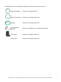
Compatible Sensors for RanchMaster Equipment which may be a part of your order.
Digital Temperature
Connects to a Digital BUS Port
Analog Temperature
Connects to an Analog Sensor Port
Humidity
Connects to an Analog Sensor Port
Wind Speed and
Direction
Connects to a WSD Port, or two Analog Sensor Ports
Rain Gauge
Connects to a Digital Counter Port
Pyranometer
Connects to an Analog Sensor Port
© Ranch Systems LLC, 2005-2008. All Rights Reserved. Reproduction without permission from Ranch Systems is prohibited.
5
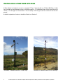
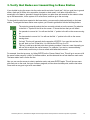
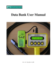
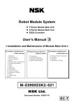
INSTALLING A WEATHER STATION
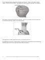
A Base Station is intended to mount to a standard 3” Pipe. Typically this is a 3” Black ABS Pipe, 10 feet
long, available at most hardware stores or building supplies. For installations that need a height taller than
10 feet, a 3” Steel pipe is recommended. This is usually a 20 foot pipe cast into concrete 5 feet into the
ground.
A detailed explanation of where to install the Station is in Section 5.
Illustration 1: Weather Station on 10' ABS Pipe
6
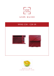
Illustration 2: Weather Station on 20' Steel Pipe
© Ranch Systems LLC, 2005-2008. All Rights Reserved. Reproduction without permission from Ranch Systems is prohibited.
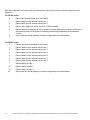
1. Unpack and Verify Components
1.
2.
3.
4.
5.
Base Station.
Solar Panel or 120VAC Wall Adapter.
Radiation Shield with Temp and Relative Humidity sensors.
Wind Speed and Direction sensor.
Rain Gauge.
If you think that you are missing any components, please contact Ranch Systems support at
[email protected]
IMPORTANT
It is a good idea to follow the verification steps in the following sections first, in order, before installing. Any
number of problems could have happened in shipping. You may also start the installation by skipping to
Section 5. You will be referred to the verification steps as you install. However, it is much more difficult to
diagnose problems when everything is mounted in the field.
© Ranch Systems LLC, 2005-2008. All Rights Reserved. Reproduction without permission from Ranch Systems is prohibited.
7
2. Verify that Base Station powers up
The Base Station ships with the main battery disconnected. The battery gets connected when either a solar
panel or a wall chargers is inserted.
If you have ordered the wall charger, and you do not plan to deploy the Base Station immediately, it is a
good idea to start by plugging in the wall charger at this point and charging the Base Station for 24 hours.
Alternatively, you may insert the solar panel immediately, which will prompt the Base Station to start – even
if the solar panel is not exposed to sun. This is because the solar panel plug itself serves to connect the
internal battery.
If the Base Station does not start up, please contact Ranch Systems support at [email protected]
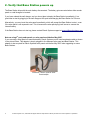
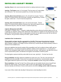
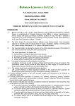
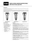
Note on using 3rd party solar panels, or solar panels sold before May 2007.
If you are using a solar panel not manufactured by Ranch Systems you will need an adapter cable as shown
in the picture below. This adapter is simply plugged in-line between solar panel and Base Station. This
adapter is also required for Ranch Systems solar panels sold before May 2007 when upgrading to newer
Base Stations.
Illustration 3: Ranch Systems Solar
Panel Adapter
8
© Ranch Systems LLC, 2005-2008. All Rights Reserved. Reproduction without permission from Ranch Systems is prohibited.
3. Verify that Base Station connects to Server
Make sure that the Base Station is placed somewhere with adequate cellular connection. Ranch Systems
uses GSM or CDMA cellular signal, depending on what you ordered. These types of cell phones can be
used to gauge if there is signal. Phones from Cingular, Edge Wireless, and T-Mobile are typically GSM.
Phones from Sprint or Verizon are typically CDMA. Nextel is not typically GSM or CDMA.
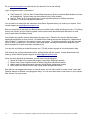
Once the Base Station is turned on, and adequate signal is available, it should begin to synchronize with the
Ranch Systems server. Give it a few minutes to get connectivity and synchronize before starting to
troubleshoot. This is a good time to get familiar with the Base Station display:
Illustration 4: Base Station Display
The number in the uppermost right hand corner of the screen marks the cellular signal strength. The
number 9 or + marks the highest signal strength possible, whereas a zero would mark no signal being
received. Typically a signal of 3 is sufficient, although 4 or 5 are preferable.
The number directly below this one on the screen indicates the connection status of the Base Station. The
meaning of this number is as follows:
1 – 3 No connection yet. If this persists, it is typically when there is insufficient cellular coverage. If
this is the problem, either relocate the station to a place with better strength, or contact Ranch
Systems, as a high-gain cellular antenna can be fitted to improve signal performance.
4
Idle state – Base Station is connected to the cellular network and to the Ranch Systems
server, but not currently synchronizing. This should be the state most of the time during
normal operation.
5
Not used
6
Base Station is in process of connecting with the Ranch Systems server (Network Operating
Center), but not yet connected.
7
Data and control information is being synchronized with the server. This status will only show
briefly when data is exchanged.
When you first initialize the Base Station, the cellular signal strength will appear as a dash (-) and the station
connection will likely be a 2. The time and date will likely be inaccurate as well. As the system begins to
boot up, the cellular signal strength will show up as a number, and the station connectivity should jump from
2 to 4 to 6 and eventually briefly 7. If the time of the unit is not correct the system will discover this at this
point and time will be adjusted and unit reset automatically.
At this point the Base Station is running and receiving sensor information from nodes, and there is typically
no more field programming to perform. All the programming of functionality is done in the Internet software.
If the Base Station does not start up, please contact Ranch Systems support at [email protected]
4. Verify sensor data in the on-line application
Whether you checked the data arriving to the Base Station, or not, the most important test is to verify that
sensor data is arriving correctly into the on-line application.
© Ranch Systems LLC, 2005-2008. All Rights Reserved. Reproduction without permission from Ranch Systems is prohibited.
9
Go to www.ranchsystems.com and click the “My Account” link on the left side.
Log in using three pieces of information:
The Property ID. This is a short ID describing the property where a particular Base Station and node
will be deployed. Several users may have access to any given property.
● User ID. This is an ID of a particular user. A user may have access to multiple properties.
● Password. This is the user-specific password.
●
You will receive an email with this information from Ranch Systems before you receive your system. If not,
contact support at [email protected].
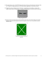
Now you should see a map with your Base Station and nodes clearly visible as little green icons. Try clicking
on any one of them, and you'll see a a graph of all the sensor data associated with that station or node
(even system data, like battery levels).
You will also see specific sensors listed below the green icons. These are the sensors that have been
specifically assigned to a zone or block. By default all the external sensors are assigned to a default block
called “Default” - indicated on the map by a green, square box. Try clicking anywhere inside this box, but
not on a node or sensor icon. You will see a zone/block graph, showing all the sensors assigned to this
block (irrespective of which node they are attached to).
You can also try clicking on a specific sensor icon. This will produce a graph of only that sensor's data.
Click through the various nodes and sensors, getting familiar with the system. If some data seems to be
missing, contact Ranch Systems support at [email protected].
Once you have deployed the hardware, you will want to do the following:
1. Upload an image of your particular property (using Zone Definitions screen)
2. Define each of your irrigation blocks or zones (using Zone Definitions screen)
3. Attach specific nodes and sensor to blocks (using Sensor Assignment screen)
4. Place nodes and sensors on the map (using Sensor Assignment screen)
Note that you can assign same sensor to several zones, and it is often useful to create “virtual” zones that
combine sensors in different, non-geographic ways. You can even draw these virtual zones on your map as
little “buttons” for easy access.
10
© Ranch Systems LLC, 2005-2008. All Rights Reserved. Reproduction without permission from Ranch Systems is prohibited.
5. Install Base Station in the field
Selection of the site for the Base Station is essential for good performance of RanchMaster installation. It
should generally be placed at the highest point in the vineyard where it has a good line-of-sight to each
deployed sensor node. Also keep in mind where you might want to deploy nodes in the future.
For RSRF Nodes, the maximum distance line-of-sight cannot generally exceed 1/3 mile, and should
preferably be less. If your vineyard is flat, the distance will generally have to be less as the line-of-sight is
subject to “ground interference” - especially as foliage increases during the season.
For Mesh Nodes, the same considerations apply, although the line-of-sight distance can be up to 1 mile.
The Base Station comes supplied with a mounting bracket assembly with metal bands that will fit around a
variety of posts, both round and square. The ideal size of post is 3”, and very often a 3” ABS drainpipe is
used, which can bee secured to another post, such as a trellis end post. However, any tall, sturdy wooden
pole, ABS, PVC or steel pipe will work. The pipe should be straight, vertical and plumb.
Note, that all antennas on top of Base Station should be free of obstructions, and as high from the ground
as feasible. It is usually preferred that the display is roughly eye-height. However, the higher the Base
Station, the longer the possible range to nodes.
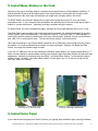
If you use a 3” ABS pipe, and you are installing the Weather Station Edition, you might consider drilling 1.5”
holes at various places to accommodate running wires inside the pipe which both protects and leaves a neat
appearance. Generally the following holes are drilled: 1 just below Base Station, 1 at the desired height of
radiation shield, 1 at about 2 feet above Base Station for solar panel, and 1 or 2 near top of pipe for the
wind, rain, and/or UV sensors.
Illustration 5: Typical Base Station
mounting on 3” ABS drain pipe
Illustration 6: Drain pipe typically secured
to end post with large metal bands.
6. Install Solar Panel
If you ordered the solar panel from Ranch Systems, you typically also ordered the pole mounting hardware.
© Ranch Systems LLC, 2005-2008. All Rights Reserved. Reproduction without permission from Ranch Systems is prohibited.
11
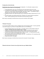
These mount kits vary slightly by type of panel, but generally look like the picture below.
Illustration 7: Solar Panel Assembly
The panel assembly consists of 2 main parts:
1. U-Channel piece placed perpendicular to pole and fixed with U-bolt
2. Two long Angle Brackets to be bolted to the panel and Channel Bracket.
If your type of panel assembly is shipped in parts, you need to first assemble these parts before placing on
the pole:
1. Place the square nuts into the slots on the shorter side of the panel. Slide one to each side of the
hole in the center of the slot.
2. Place the small angle pieces over the slots to align the hole with the nuts. The vertical side with one
hole should be towards the middle of the panel, and the single hole should be towards the side with
the wire and black cap. Install all screws loose enough for the angle to move.
3. Place the U-Channel bracket inside the two angle pieces, and install the two screws with lock-nuts
provided, keeping them loose enough for the pieces to rotate.
4. Tighten the screws on the panel first. Then allow the panel to touch the Channel Bracket, and
tighten those two screws.
Next, you go to the actual pole and set the whole assembly to the pole using the U-bolt. Finish by turning
the panel to a straight south exposure. The bracket should be made for at an appropriate angle to the sun
for your location, typically 45 degrees for California.
If using a drilled ABS Pipe, run the cable down through the pipe and out just under the Base Station.
Plug the solar panel cable into the Base Station (See Illustration 5 in the next section), which will cause the
Base Station to start (even without sunlight).
Now follow the Verification Steps in Sections 2 and 3 to make sure you have a connection to the
Ranch Systems servers.
If using a steel pipe or other solid pole, install any included sensors first (See Section 7), then arrange the
cable neatly and tie down with zip ties.
12
© Ranch Systems LLC, 2005-2008. All Rights Reserved. Reproduction without permission from Ranch Systems is prohibited.
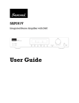
7. Connect Sensors to Weather Station
You will find the following connectors on the bottom off your Base Station:
Illustration 8: Base Station Connectors
1) Solar Panel or AC Adapter
6) Temperature (TP)
11) Relay 1
2) RS232 Serial
7) Relative Humidity (RH)
12) Relay 2
3) RS485 Serial
8) Rain Gauge (RG)
13) Relay 3
4/5) Wind Speed and Direction (WS/WD)
9) Pyranometer (PY)
14) Relay 4
When using a drilled pipe, run each wire through the pipe before connecting. When using a solid pipe or
pole, connect ALL wires first, then secure them to the pole or pipe with zip ties.
Note that the actual sensors shipped with your weather station may vary depending on your order, but the
following are the general steps required to install your weather station:
1. First make sure your Base Station is mounted following Section 5.
2. The Radiation Shield will have the Temperature and Relative Humidity sensors already installed
inside the shield. Attach the shield with sensors to the pipe or pole at the desired height, typically
fruit zone height. First screw the mounting bracket to the shield with hardware provided. Use the
bands provided with shield to mount to the pipe. Then connect the sensors to the Base Station. The
RH sensor will have some black heat shrink visible at the shield, and the cable length will be longer.
The TP sensor cable will be shorter.
3. Next, attach the rain gauge to the pipe or pole. A U-Bolt is provided for a 3” Pipe, this should be
several inches down from the top of the pipe, leaving the top of the rain gauge well above the pipe.
Later test it using instructions below.
4. Finally, assemble the Wind Speed and Direction sensors with the hardware and directions in the box.
Then using either the bands provided for a 3” Pipe or Pole, or the hardware provided in the box,
mount the sensor to the pipe just below the rain gauge mount. Point the sensor arm in a direction so
the pipe and rain gauge do not interfere with prevailing winds. Connect to Base Station. Note that
you will need to configure the wind direction, See below.
At this point your station is ready to use, and you should see data entering the web application within 15 - 30
minutes.
© Ranch Systems LLC, 2005-2008. All Rights Reserved. Reproduction without permission from Ranch Systems is prohibited.
13
Configuration of wind direction
Wind direction is the only sensor that needs specific configuration. You will need a compass or know
exactly which direction North is to do the following:
1. Take off the weather vane on top. This effectively forces the direction sensor to be 'stuck'
2. Press ENTER on the Base Station for the main menu, scroll down to “System” and press ENTER,
scroll down to “Device Status” and press ENTER, scroll down to “ADCs”. You should now hear a
beep about once per second, this is the update rate of the data.
3. Watching the value for A2, adjust the sensor until you find the point where it bounces from 0.0 to 5.0
V.
4. Place the weather vane pointing exactly North. Be careful not to move the dial as you sight out
North. Finish by tightening the set screw with the hex key provided in the box.
Note it may be necessary to hold the left arrow key for a bit to leave the “ADCs” display.
Testing the rain gauge
You must open the Rain Gauge to remove a shipping strap on the moving part inside. It is also a good idea
to test the rain gauge, so you know it is ready when the rain hits. Do the following:
1. Access the tipping bucket of your rain gauge – this usually means you twist the whole 'hood' and
remove it. Otherwise follow the instructions with your gauge.
2. CAREFULLY cut the zip tie inside with wire cutters. It can be very close to the wires, and the
mechanics are sensitive enough you should not push or pull on the tie with a knife or blade.
3. From the “Device Status” menu described above, select “Counters”. You should now hear a beep
about once per second, this is the update rate of the data.
4. Now manually tip the bucket inside the gauge a few times. You should see “CA” incrementing. Note
that it may not always start at zero.
5. Replace the bucket on the gauge.
Note it may be necessary to hold the left arrow key for a bit to leave the “Counters” display.
Follow the directions in Section 4 to verify the data from your Weather Station.
14
© Ranch Systems LLC, 2005-2008. All Rights Reserved. Reproduction without permission from Ranch Systems is prohibited.
INSTALLING SENSOR NODES
The key to good node installation is achieving a clear line-of-sight connection to the base station, ensuring
good data connectivity at all times. Nodes should be placed above maximum crop canopy height.
The RS100 and RS200 nodes have been manufactured to be compatible with easily available materials :
White PVC pipe or EMT Conduit pipe, UV resistant zip-ties and Stainless Steel Hose Clamps. These
types of pipe are already widely used in vineyards, so the pipe, fittings and tools are readily available at low
cost. The result is faster and less expensive installations. They are usually purchased in 10' lengths, which
makes a good height for most locations, as long as you don't use “overhead” equipment.
Often we recommend attaching the node to the pipe before attaching the pipe to the line post, as a small
bull ladder is required to reach up to the top of a 10 foot pipe once installed.
As with the base station, ensure that the node antennas are free of obstructions, as well as potential future
obstruction from growing foliage.
Follow steps 1 and 2 for each node you received. Then follow step 3 to verify all nodes after they
have had 15-30 minutes to report.
© Ranch Systems LLC, 2005-2008. All Rights Reserved. Reproduction without permission from Ranch Systems is prohibited.
15
1. Install Node in the field
RS200 Nodes are shipped with an integrated mounting assembly which holds both the solar panel in place,
as well as a ¾” EMT Conduit connector. All you need is to attach a ¾” EMT Conduit pipe to a line post in
the vineyard (using metal bands) and hand-tighten the nut with the RS200 node on top.
Illustration 9: RS200 Node Assembly ready to
deploy on 3/4” EMT Conduit pipe.
Illustration 10: RS200 Deployed on
10' Conduit pipe.
RS100 Nodes are attached to a ¾” four-way PVC tee using two UV/weather resistant tie wraps passed
through their mounting flanges. The assembly is then easily slipped onto the pipe in the field.
Illustration 11: RS100 Sensor
Node Assembly
Illustration 12: RS100 Deployed
on 10' PVC pipe
2. Connect Sensors to Sensor Node
16
© Ranch Systems LLC, 2005-2008. All Rights Reserved. Reproduction without permission from Ranch Systems is prohibited.
Both the RS100 and RS200 nodes accept mostly the same types of sensors. If a Radiation Shield is used
on any sensor, make the sensors are mounted in the shield by follow the section “INSTALLING RADIATION
SHIELD” before you connect them to the node.
RS100 Nodes come completely ready, meaning they are already transmitting data, and there is nothing to
do but plug in the sensors.
RS200 Nodes have an internal battery and an attached solar panel. However, they ship with the solar panel
connector disconnected, which leaves the internal battery disconnected, and the node is not transmitting. To
activate an RS200 node, simply plug in the solar panel. Even without sunlight, the RS200 will now start
communicating with the base station.
Illustration 13: RS100 Node
Illustration 14: RS200 Node
Note the solar connector on RS200 nodes.
For both types of nodes, you must make sure the right sensors are plugged into the right ports.
RS100 Nodes - You can see what sensor type is expected in the two white squares on the front label of the
nodes.
RS200 Nodes - These are slightly more dynamic, due the higher level of programmability. You may have
received one of these types of RS200 nodes:
●
RS200-S has 6 sensor ports.
●
RS200-PRO has 6 sensor ports and 3 relay ports. It will also function as a repeater for RS100
Nodes.
The initial programming of these ports will be listed on a card shipped with the unit, and should be
available after logging into the RanchSystems website. If you have not received such a card, please
contact [email protected].
You should have received sensors to match your nodes, and at this point you can go ahead and plug them
into their respective ports.
© Ranch Systems LLC, 2005-2008. All Rights Reserved. Reproduction without permission from Ranch Systems is prohibited.
17
The most common sensor types are represented as follows:
TP
Temperature
HM
Relative Humidity
WS
Wind speed
UV
UV radiation
PY
Pyranometer (solar radiation)
FL
Water flow (turbine sensor)
PS
Pressure (usually water pressure)
WL
Water Level (either in-pipe or submersible)
If you don't seem to have a matching set of nodes and sensors, please contact Ranch Systems support at
[email protected]
18
© Ranch Systems LLC, 2005-2008. All Rights Reserved. Reproduction without permission from Ranch Systems is prohibited.
3. Verify that Nodes are transmitting to Base Station
If you decided to plug the sensor into the nodes and do an indoor “bench test”, this is a good time to go and
make a fresh pot of coffee, drive around the vineyard or check email. It will take a little while for a
meaningful set of data to “percolate” through the system, so rather than wait around for the nodes to show
up on the base station, let the system sit for a few hours, and then go to the next step.
To check which nodes have reported to the base station, you can use the keyboard directly on the base
station. To navigate the base station menu system, you'll need to get familiar with the following buttons:
The enter key generally selects the item currently pointed out on the screen. Pay attention
to the little “>” symbol to the left on the screen – it shows the item that you will select.
Go upwards in a menu list. You will see the little “>” pointer to the left on the screen moving
up.
Go downwards in a menu list. You will see the little “>” pointer to the left on the screen
moving down.
Go back. This key will generally do the opposite of ENTER. If you went into an item, this
key will 'back you out' of that item. It is a bit like the ESC key on a PC.
This key is used as a decimal point when entering numbers. However, more frequently you
will use this to refresh the current screen. For example, if you are in a screen showing
sensor data, use this key to force a refresh with latest data received.
For example, from the top menu, try hitting ENTER on the “Sensor Status” item. This will go to a menu of all
the sensor nodes currently “visible” to the base station, and the date and time of last data from each node.
The base station itself is on the first line.
Now you can use the arrows to select a particular node, and press ENTER again. This will show a menu
with each port on the node, the type of sensor assigned, minutes since last data point, and the last value.
Press enter on any port to get even more detail.
© Ranch Systems LLC, 2005-2008. All Rights Reserved. Reproduction without permission from Ranch Systems is prohibited.
19
Note that nodes have more ports than the physical ports. Here is an overview of all the 'logical' ports you
might see:
For RS100 nodes:
0
Reports the internal temperature of the node
1
Reports data from the external sensor port 1
2
Reports data from the external sensor port 2
3
Reports the voltage level of the internal 3.5V lithium battery
4
Reports either the voltage level of the internal 5V voltage generator (for sensor excitation) or
the internal humidity of the node (for detecting malfunctions) depending on the hardware
revision.
9
A port used for internal reporting of system configuration to the base station
For RS200 nodes:
0
Reports the internal temperature of the node
1
Reports data from the external sensor port 1
2
Reports data from the external sensor port 2
3
Reports data from the external sensor port 3
4
Reports data from the external sensor port 4
5
Reports data from the external sensor port 5
6
Reports data from the external sensor port 6
7
Reports status of relay 1
8
Reports status of relay 2
9
Reports status of relay 3
10
20
A port used for internal reporting of system configuration to the base station
© Ranch Systems LLC, 2005-2008. All Rights Reserved. Reproduction without permission from Ranch Systems is prohibited.
INSTALLING RADIATION SHIELD
The radiation shield may require some assembly, or even to be partially disassembled to install sensors. If
the shield is completely unassembled, start by installing the threaded rod into the top plate, this is the only
plastic piece with threaded holes. Then add one of the solid plates over the threaded rods.
Illustration 15: Installing threaded rod on
Radiation Shield
Illustration 16:
Completed
Radiation Shield
Next you should mount the sensors to the plastic rod included. For Temperature and Relative Humidity,
they should be aligned towards one end of the plastic rod, with the black cap of the humidity sensor sticking
out from the temp sensor, and both sensors about half an inch from the end. Use electrical tape to secure
sensors to the rod. Then install the rod in one of the raised slots on the solid plate.
Illustration 17: Install sensors in Radiation
Shield
Illustration 18: Assembling Radiation Shield
Plates.
Then add all the Middle Plates, feeding the wires through the opening in the middle.
© Ranch Systems LLC, 2005-2008. All Rights Reserved. Reproduction without permission from Ranch Systems is prohibited.
21
Finish by adding the last two solid plates, and installing the wing nuts. Tighten until the plates are close
together. DO NOT OVER TIGHTEN ! The threaded rod is much stronger than the plastic it is mounted to.
Now install the mounting arm with the screws provided. It will on fit on one side, but can be mounted with
the vertical side pointing up or down, as your space requires.
If the shield has two U-Bolts, these will fit onto the ¾” pipe that the node is on.
If the shield has an aluminum C-channel bolted to it, slide the metal band between the channel and bracket,
and this will get secured to the 3” pipe that the Base Station is mounted to.
22
© Ranch Systems LLC, 2005-2008. All Rights Reserved. Reproduction without permission from Ranch Systems is prohibited.
INSTALLING AQUASPY PROBES
AquaSpy Sensor is the most economical solution for reading moisture at a single
depth.
AquaSpy Turf Probes come in 12 inch length. The first sensor is 2 inches below
top of the probe. The 6 sensors are spaced every 2 inches down the probe.
the
AquaSpy Below Ground Probes come in 20, 40 and 60 inch lengths. The first
sensor is 2 inches below the top of the probe. Sensors are spaced every 4 inches
the probe, which has 5, 10 and 15 sensors respectively.
down
AquaSpy Above Ground Probes come in 40 and 60 inch lengths. The first
sensor is 4 inches below the bottom of the blue cap. Sensors are spaced every 4
inches down the probe, which has 10 and 15 sensors respectively.
Irrigation Management Unit (IMU)
Also called an “Irrigation Zone”. A properly installed AquaSpy probe collects soil moisture data you can use
to optimise your irrigation strategy for the whole IMU. Plant response to irrigation will be similar across a well
defined IMU. Monitoring water use at a representative site tells you how plants across the IMU are affected.
For instance, on a golf course a fairway is an IMU, a green is another.
Installation Site Considerations
Where possible, soil type should be representative of the IMU. Plant type and growth stage should be
representative of the IMU. Irrigation application is representative of the IMU. The probe is not installed
where irrigation overlaps or at its edge. Perform a site survey to confirm that the chosen telemetry solution is
effective at the installation site.
Select an installation site where the probe will be accessible but will not be subject to heavy traffic and has
adequate security. Turf probes are typically installed in shallow-rooted crops like turf, i.e. a golf green or
fairway. Probe installation depth varies to suit the plant and soil type. Install probes in the plant line and root
zone of representative plants, and between the irrigation source and the reference plants.
For drip irrigation systems install the probe within the root zone, typically 4 – 5 inches from the drip.
Slurry Installation: AquaSpy probes are installed into a thick slurry mix. The slurry uses soil from the
installation site where possible. If that soil will not make thick slurry Kaolin is recommended instead.
Filling gaps between the probe and soil, slurry is displaced around the probe during probe installation.
Direct Installation: Only the Turf and 50 cm (20 in) probes can be installed directly into an Auger55 hole
without the need for slurry. There must be a tight fit, with no air gaps between the probe and soil.
Because AquaSpy Soil Moisture Probes contain precision electronics hitting a probe voids its warranty.
If you want to Direct Install other AquaSpy Probes please contact AquaSpy for advice.
© Ranch Systems LLC, 2005-2008. All Rights Reserved. Reproduction without permission from Ranch Systems is prohibited.
23
During the installation of the probe :
•
Do not compact the soil.
•
Do not damage the reference plants near the probe.
1. Remove loose material around the location for the hole.
2. Use an auger to dig a hole slightly larger than the probe. Using
water with the auger makes digging easier and minimizes
damage to the soil structure.
3. Make the hole about 6 inches deeper than the probe length.
4. Add sieved soil or Kaolin to water, making a thick slurry mix. Make sure there are
no lumps, yet it should be “pourable”. Similar to Pancake Batter.
5. Fill the hole half way with slurry.
6. Push the probe firmly into the hole with a gentle circular motion, displacing slurry
around all sides of the hole as the probe reaches its depth.
7. If slurry is not displaced around all sides of the hole, withdraw
the probe, insert more slurry and install the probe again.
8. Clear excess slurry away from the probe.
9. Neatly run wire to Node or Base Station, plug in to RS485 Port.
24
© Ranch Systems LLC, 2005-2008. All Rights Reserved. Reproduction without permission from Ranch Systems is prohibited.
RS100 BATTERY REPLACEMENT
Tools Needed
•
Phillips screwdriver
•
Needle nose pliers
•
Vice (mounted securely)
•
Leather Gloves
•
Small screwdriver
Supplies Needed
•
3.6 Volt Lithium-ion Battery
•
GE “Silicone I” 100% Silicone Rubber
Sealant
Illustration 19: RS100 Battery Replacement Tools
Remove RS100 from field location, being sure to mark each sensor cable with the corresponding port
number. A piece of white electrical tape and a permanent pen work well for
this.
1) Turn the unit so that the battery cover is face up and the four phillip
screws are exposed. You would do best to place the RS100 on
something soft (ie. A glove) to begin, so that it doesn't scratch the
coating or label. Loosen all screw first with a screwdriver. Finish
removing screws by hand, gently pull out on the screw as you turn it,
this is to remove the rubber o-ring on the screw which can get stuck
inside the screw hole. If the o-ring gets lodged in the hole, a small
screwdriver can push them out.
Illustration 20: Partially
Remove RS100 Screws
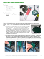
2) Now remove the battery cover by carefully separating it from the body of the RS100. To do so open
the vice to fit a glove between the jaws of the vise with room to put the edge of the battery cover
being careful not to scratch it or press on the antenna. Pull outward and press down on the body of
the RS100, being careful not to push on the antenna or sensor plugs. The cover is held in place by a
small bead of silicone so some pressure will be needed.
Illustration 23: RS100 In Vice
Illustration 22: RS100 In Vice
Illustration 21: Removing RS100 Cover
© Ranch Systems LLC, 2005-2008. All Rights Reserved. Reproduction without permission from Ranch Systems is prohibited.
25
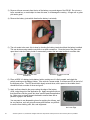
3) Remove silicone remnants from the rim of the battery cover and edges of the RS100. Do not use a
knife, screwdriver, or metal object to clean this area, it will damage the coating. A finger nail or guitar
pick works great!
4) Remove the battery (note which direction the battery is oriented)
Illustration 24: Remove RS100 Battery
5) The unit needs to be reset, this is done by shorting the battery terminals without the battery installed.
This can be done using needle nose pliers or a small screwdriver. Close the jaws of the pliers and
open them inside the battery holder to momentarily contact the two metal terminals on either side.
Illustration 25: Reset Unit with
Screwdriver
Illustration 26: Reset Unit with
Pliers
6) Place a NEW 3.6v battery inside battery holder, making sure it is firmly seated, and check the
polarity marking on the Battery Holder. If the node is a newer model, it will have an LED to the left of
the Antenna screw. The LED should blink slowly several times, with a pause in the middle, then it
should blink fast a number of times and go off.
7) Apply a silicone bead to the groove along the edge of the battery
cover, using the point of the application tip. Apply enough silicone so
that the silicone fills the groove but does overflow past the application
tip. Make sure to visually inspect the bead to ensure there are no
pockets or gaps in the silicone.
You may want to use disposable gloves for applying the silicone, and
be very cautious, as it can get quite messy and become very difficult
to remove from clothing, skin, hair, and equipment.
26
Illustration 27: Silicone around
the Cover Edge
© Ranch Systems LLC, 2005-2008. All Rights Reserved. Reproduction without permission from Ranch Systems is prohibited.
8) Place the battery cover on the RS100 aligning the holes in the cover with the holes in the body of the
unit. Please do not apply pressure yet, as it may make the application of the silicone uneven.
9) Prepare the screws to fasten the cover the body, by inspecting for torn washers, or areas in the
washers where rubber is falling away or is missing. Roll the washers to meet the head of the screw.
Illustration 28: RS100 Screws Left OK, Right NOT OK
10) Place the screws in the holes and turn until snug and the head of the screw meets the battery cover surface.
Work from one screw and then tighten the screw on the opposite corner so as to evenly distribute pressure
across the cover.
Illustration 29: Screw Tightening
Sequence
© Ranch Systems LLC, 2005-2008. All Rights Reserved. Reproduction without permission from Ranch Systems is prohibited.
27
WIRING DIAGRAMS
Diagrams are for the Plugs on the end of wires, from the “inside” or “wiring side” of the connector.
This is also the same view of the Sockets mounted on devices as viewed from “outside” the device.
Pins on Plug
Description
(Cable end Connector)
Manufacturer and Part
Number for plugs
Solar Panel, AC Adapter.
Small Size for 1 Watt Supply, +V >= 12 VDC
Large Size for 10 Watt Supply, +V >= 14.4 VDC
Two GND Pins are connected in the plug to act as the
power switch
RM200 Series
SwitchCraft # EN3C3F
Analog Sensor, Digital Counter, Digital BUS
+V = 5.0 VDC
Analog Signal = 0 – 5 VDC
Counter Signal = 5 VDC Pulse
BUS Signal = 1-Wire® Bus
Conxall # 16282-3PG-315
Wind Speed and Direction
+V = 5.0 VDC
Speed = Digital Counter
Dir = Analog Sensor
Conxall # 6282-5PG-3DC
Relays
Conxall # 16282-2SG-315
RS200 Series
Conxall # 16282-3SG-315
Power Output: 1 = +V ; 2 = GND
DC Latching : 1 = -V ; 2 = +V
Switch N.O. : 1,2 = Contact Closure
RS485 Serial
+V = 9.0 VDC
Conxall # 6282-4PG-3DC
RS232 Serial
+V = 9.0 VDC
Conxall # 6282-6SG-3DC
RS485/RS232 Serial
+V = 9.0 VDC
Conxall # 6282-8SG-3DC
Power Output
+V = 12.0 VDC
Conxall # 16282-2PG-315
Plugs can be ordered from RanchSystems, or online from Digikey or Allied Electronics.
Note that the last 3 digits of Conxall numbers refer to cap style and grommet size, which may be substituted.
28
© Ranch Systems LLC, 2005-2008. All Rights Reserved. Reproduction without permission from Ranch Systems is prohibited.
FURTHER HELP
This guide should have given you the tools needed to get started, as well as an overview of the various
features available to you.
For detailed help and instructions on the various features, please use the sidebar to access the desired
feature, and then scroll to the bottom of the web page, where you will find additional instructions. Each time
you click further into the application, the bottom of the page will show the relevant help information for that
stage.
You can quickly identify the web page help texts by looking for the context help icon:
However, we at Ranch Systems completely understand that you are likely to have questions and problems
that go beyond what we have anticipated in our help texts, and we are always available to help you on the
phone or by email:
Ranch Systems phone support: 415 898 5900 ext. 3
Ranch Systems email support: [email protected]
© Ranch Systems LLC, 2005-2008. All Rights Reserved. Reproduction without permission from Ranch Systems is prohibited.
29
Alphabetical Index
Email...................................................................................................................................................3, 10, 29
Help..........................................................................................................................................................3, 29
Mesh Node...............................................................................................................................................4, 11
Relay...................................................................................................................................................4, 13, 28
RM200............................................................................................................................................................4
RM210............................................................................................................................................................4
RS100.............................................................................................................................................................4
RS200.............................................................................................................................................................4
RS210.............................................................................................................................................................4
RS232.....................................................................................................................................................13, 28
RS485.................................................................................................................................................4, 13, 28
RSRF Node..............................................................................................................................................4, 11
Solar panel..........................................................................................................................................8, 11, 12
Support...........................................................................................................................................................3
User Manual...................................................................................................................................................3
Illustration Index
Illustration 1: Weather Station on 10' ABS Pipe..............................................................................................6
Illustration 2: Weather Station on 20' Steel Pipe.............................................................................................6
Illustration 3: Ranch Systems Solar Panel Adapter.........................................................................................8
Illustration 4: Base Station Display..................................................................................................................9
Illustration 5: Typical Base Station mounting on 3” ABS drain pipe...............................................................11
Illustration 6: Drain pipe typically secured to end post with large metal bands..............................................11
Illustration 7: Solar Panel Assembly..............................................................................................................12
Illustration 8: Base Station Connectors.........................................................................................................13
Illustration 9: RS200 Node Assembly ready to deploy on 3/4” EMT Conduit pipe.........................................16
Illustration 10: RS200 Deployed on 10' Conduit pipe....................................................................................16
Illustration 11: RS100 Sensor Node Assembly..............................................................................................16
Illustration 12: RS100 Deployed on 10' PVC pipe.........................................................................................16
Illustration 13: RS100 Node..........................................................................................................................17
Illustration 14: RS200 Node..........................................................................................................................17
Illustration 15: Installing threaded rod on Radiation Shield............................................................................21
Illustration 16: Completed Radiation Shield..................................................................................................21
Illustration 17: Install sensors in Radiation Shield.........................................................................................21
Illustration 18: Assembling Radiation Shield Plates......................................................................................21
Illustration 19: RS100 Battery Replacement Tools........................................................................................25
Illustration 20: Partially Remove RS100 Screws...........................................................................................25
Illustration 21: Removing RS100 Cover........................................................................................................25
Illustration 22: RS100 In Vice........................................................................................................................25
Illustration 23: RS100 In Vice........................................................................................................................25
Illustration 24: Remove RS100 Battery.........................................................................................................26
Illustration 25: Reset Unit with Screwdriver...................................................................................................26
Illustration 26: Reset Unit with Pliers.............................................................................................................26
Illustration 27: Silicone around the Cover Edge............................................................................................26
Illustration 28: RS100 Screws - Left OK, Right NOT OK...............................................................................27
Illustration 29: Screw Tightening Sequence..................................................................................................27
30
© Ranch Systems LLC, 2005-2008. All Rights Reserved. Reproduction without permission from Ranch Systems is prohibited.