1
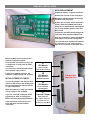
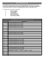
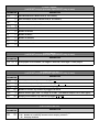
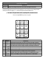
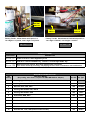
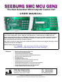
SEEBURG SMC MCU GEN2
"The Next Generation Microcomputer Control Unit"
USER MANUAL
Rear View
Front View
The GEN2 MCU is the "Next Generation" Microcomputer Control Unit for the last of the Seeburg 45's jukebox.
This includes models SMC1 (Disco), SMC1 JR. (100-79M 'Da Vinci'), SMC2 (Phoenix) and SMC3 (Prelude).
Using highly advanced technology, the GEN2 MCU board offers many years of reliable, trouble-free operation
with it's 2-chip design along with many new features. Installations a snap! Only three connectors. You can
have your jukebox up and running in a matter of minutes.
Easy setup ! No wires to solder. Select your options and features directly from the keypad. All setup is saved
in memory and doesn't need batteries.
What the Seeburg experts had to say ...
"It's a WINNER ! This new board cures ALL of the problems
inherent in the original design and even in the re-design !"
Features
•
•
•
•
•
•
•
•
•
•
•
•
•
Bright blue LED display with intensity control
Keypad programmable PRICING SETUP
Keypad forward/backward display of AUDITS
Keypad forward/backward display of LEAST POPULAR selections
Displays 25 of the Least Popular records.
No batteries needed
True FREE PLAY operating mode
Programmable save/erase credits or selections at power up
Programmable 80 or 50 record selection mode
Programmable wallbox type: DEC or 3-wire (requires translator/adapter)
Programmable random autoplay: off, 1-98-minutes or continuous
Programmable autoplay record sides: A, B or alternate A & B
Factory Test Mode for diagnostic troubleshooting
Data Sync Engineering
P.O. Box 539, 2 Footbridge Lane
Blairstown, New Jersey 07825
TEL: (908) 362-6299
FAX: (908) 362-5889
www.datasynceng.com
Copyright © 2010 Data Sync Engineering. All Rights Reserved.
Designated trademarks and brands are the property of their respective owners.
GEN2 MCU INSTALLATION
MCU REPLACEMENT
Unplug the battery / regulator connector.
Remove the six nuts on the front panel.
Wiggle the old MCU boards out through
the back of the enclosure.
Remove the six 13/64" 8-32 male-to-male
spacers from the old MCU board stack.
Using the six provided nuts, hand tighten
the six male-to-male spacers to the new
MCU board.
Position the new MCU board through the
front panel holes and hand tighten nuts.
Align the connectors, display and keypad
then tighten nuts (do not over-tighten).
The old back cover regulators & batteries
are not used. You can remove them or
tape the old connector to the back cover.
Mount the MCU enclosure box to the
jukebox front panel brackets.
From the CPA wire harness, plug in the
J1 (keyboard), J1 (CPU) and J3 (CPU)
connectors.
The connectors are keyed with a block
at the number 2 pin position.
If your using wallbox selectors, the
translator / adapter plugs into J2 (CPU).
J1
CPU Module
7-Pin connector
Power & Mech Control
J2
CPU Module
9-Pin connector
INITIAL POWER UP CHECK
Turn on the jukebox. You may see three
dashes at the center of the display until
the record mechanism reaches the left
or right end position.
When the jukebox is ready, you should
see the credits or FP displayed.
If you see "Error ##" displayed, then a
keypad key is stuck on. Realign the
MCU to the front panel keypad buttons.
If the mechanism continues to scan
back and forth, recheck the MCU
connectors.
Wallbox Interface
J3
CPU Module
17-Pin connector
Input Signals
J1
Keyboard / Display
9-Pin connector
The signals from this
connector are not
used by the new MCU
FOR WALLBOX
ADAPTER ONLY
SERVICE MODE FUNCTIONS
The GEN2 MCU offers six service mode functions in addition to LED display intensity control. To select a
function, move the SERVICE SWITCH on the CPA panel to SERVICE MODE. The display will show SCE and the
current 2-digit record position number. While holding the CREDIT switch on, press a digit on the keypad to
select the desired function or press the Left or Right RESET key to adjust the LED display intensity.
The following numeric key functions are available:
1
2
3
4
5
8
Enter Pricing Setup
Enter Audit Mode
Enter Pop Mode
Enter General Setup
Enter Autoplay Setup
Enter Factory Test Mode
1) PRICING SETUP
(Left RESET= step to previous, Right RESET= step to next)
DISPLAYED
PARAMETER
L1
L2
L3
L4
L5
L6
L7
L8
L9
L10
L11
L12
L13
L14
L15
L16
L17
L18
L19
L20
WT
Adr
bon
bb
0
0
0
0
2
0
0
0
0
2
0
0
0
0
2
0
0
0
0
3
0
20
0
0
DESCRIPTION
(L1) Credits to add when Level 1 is reached
(L2) Credits to add when Level 2 is reached
(L3) Credits to add when Level 3 is reached
(L4) Credits to add when Level 4 is reached
(L5) Credits to add when Level 5 is reached
(L6) Credits to add when Level 6 is reached
(L7) Credits to add when Level 7 is reached
(L8) Credits to add when Level 8 is reached
(L9) Credits to add when Level 9 is reached
(L10) Credits to add when Level 10 is reached
(L11) Credits to add when Level 11 is reached
(L12) Credits to add when Level 12 is reached
(L13) Credits to add when Level 13 is reached
(L14) Credits to add when Level 14 is reached
(L15) Credits to add when Level 15 is reached
(L16) Credits to add when Level 16 is reached
(L17) Credits to add when Level 17 is reached
(L18) Credits to add when Level 18 is reached
(L19) Credits to add when Level 19 is reached
(L20) Credits to add when Level 20 is reached
(WT) Coin ratio, 0= 1-2-5-10,
(ADD R) Last level step
(BON) Last level bonus
(BB) Bill bonus
1= 1-2-4-10,
2= 1-2-5-8,
3= 1-2-4-8
2) AUDIT MODE
(Left RESET= step to previous, Right RESET= step to next)
DISPLAYED
PARAMETER
COL
T
SEL
PLA
CRD
C1
C2
C3
C4
C5
0
0
0
0
0
0
0
0
0
0
DESCRIPTION
COLLECTION total in Nickel Units (X .05 = Dollars)
total cumulative income in Nickel Units (X .05 = Dollars)
Number of SELECTIONS made
Number of selections PLAYED
Number of free Credits
Number of Nickels
Number of Dimes
Number of Quarters
Number of Half Dollars
Number of Dollar Bills
3) POP MODE
(Left RESET= step to previous, Right RESET= step to next)
DISPLAYED
PARAMETER
POP 00 0
DESCRIPTION
Least popular record number, 1st 2-digits = Record #, Last 2-digits = Times played
4) GENERAL SETUP
(Left RESET= step to previous, Right RESET= step to next)
DISPLAYED
PARAMETER
PAY
CLC
CLS
rEC
rSE
APr
0
N
n
80
0
Ab
DESCRIPTION
Free Play or credits, any numeric key toggles FP and credits
Clear Credits at power-up, any numeric key toggles no and Yes
Clear Selections at power-up, any numeric key toggles no and Yes
Number of records, any numeric key toggles 80 and 50
Remote Selector type, enter 1 or 2 digit #, 0= DEC, (see Wallbox Adapter List for other types)
Autoplay Record sides, any numeric key toggles A, b or Ab
5) AUTOPLAY SETUP
DISPLAYED
PARAMETER
APL
99
DESCRIPTION
0
1-98
99
Continuous autoplay (if no selections are available to play)
Number of no-activity minutes before autoplay selection
Autoplay disabled
8) FACTORY TEST MODE
DISPLAYED
PARAMETER
Fct 00
DESCRIPTION
Displays current 2-digit record position, press SCAN or key digit for test function
Pressing the SCAN switch will cause the record mechanism to scan. If at any time, while holding the SCAN
switch, you see the error symbol -| or |- before the 2 digit record position number, then ...
-| Limit switch 179 signal detected, but the expected position count was incorrect.
|- Limit switch 100 signal detected, but the expected position count was incorrect.
Press Left or Right RESET key to clear error symbol.
1
2
3
Detent signal
on/off timing
Detent to Limit
switch timing
Coin switch
check
4
5
6
Motor On
Play A
Play B
7
8
9
Motor Off
'Audio Control'
pulse
Show DEC
wallbox codes
RESET
KEY
#
DISPLAYED
RESULT
1
29 44 1
22 22 2
C3
3
39 4
39 5
39 6
39 7
dEC
dEC139
88888888
2
3
4
5
6
7
8
9
0
0
All 8's on LED
Display
RESET
DESCRIPTION
Show detent on/off period (mS), 1st 2 digits = on period, next 2 digits = off period
Show detent to limit switch period (mS), 1st 2 digits = limit100, next 2 digits = limit179
Coin switch check: C1=nickel, C2=dime, C3=quarter, C4=half dollar, C5=dollar bill
Turns mechanism motor on, 1st 2 digits are the current record position
Play Side A trip, 1st 2 digits are the current record position
Play Side B trip, 1st 2 digits are the current record position
Turns mechanism motor off, 1st 2 digits are the current record position
Generates "audio control" pulse, only used while in " show DEC codes" function
Show all received DEC port codes from the DEC translator or wallbox adapter
Display all 8's on LED display. (for display check and maximum power stress-test)
DETENT
SWITCH
LIMIT179
SWITCH
Factory Test #1, Show detent on/off period (mS)
1st 2 digits = on period, next 2 digits = off period
29 44
LIMIT100
SWITCH
Factory Test #2, Show detent to limit switch period
1st 2 digits = limit100, next 2 digits = limit179
1
22 22
(mS)
2
ERROR CODES
DISPLAYED
DESCRIPTION
Error 0Error 8-
Codes 00 to 09 is a stuck keypad key 0 to 9
Error 99
Mechanism motor timeout. No activity detected after 9.4 minutes.
This can be caused by a missing / not playing record or from a continuous scan malfunction.
Code 80 is a stuck Left RESET key. Code 81 is a stuck Right RESET key.
WALLBOX ADAPTER LIST
rSE
Setting
WALLBOX MODEL
(Any setting, other than 0, requires the SMC-WB Wallbox Adapter)
0
Seeburg digital DEC (requires the blue box DMT1, DEC-MCU TRANSLATOR)
160
1
Seeburg Consolette SC1/2/3/4, SCH1/2/3/4
160
Letter
2
Wurlitzer 5210, 5220, 5250
160
Number
3
Seeburg Wall-O-Matic 3W1, 3W100
100
Number
4
Seeburg Wall-O-Matic 3WA
160
Letter
5
Rowe WRA, WRB, WRC
160
Letter
6
AMI W-40, W-80, W-120, WQ200
160
Button
7
Wurlitzer 5207
104
Button
8
Wurlitzer 5225
100
Number
9
Wurlitzer 3020
24
Button
Rock-Ola 500, 1555, 1558 (and most other models)
160
Button
10
Max Sel Seq Type