1
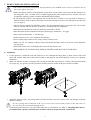
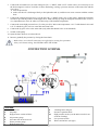
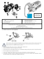
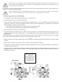
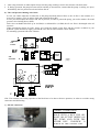
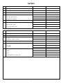
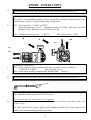
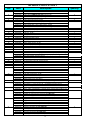
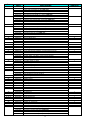
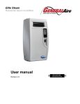
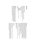
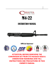
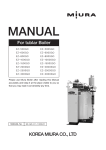
Menu
INSTRUCTIONS
FOR THE INSTALLATION AND USE
OF THE PUMPS
HWB 8040--100-110-150-200-250-300
300-400
1
Dear Customer,
We would like to thank you for the trust you granted us and are sure that you made the right choice.
The NERÒN pumps are hydraulic transformers with three actuated axial plungers transforming the power of the hydraulic
system into hydraulic power on a separate circuit (fresh and salted water, oil, glycol etc.). The HWB (high pressure water
bluster) have been developed considering the needs of the high pressure-washing field. They are equipped with specific
devices that, together with the suitable washing lance, allow an easy & safe use.
THE COMPLIANCE WITH THE FOLLOWING OPERATING INSTRUCTIONS WILL ALLOW YOU TO
USE YOUR PUMPS ACCORDING TO THE BASIC SAFETY REQUIREMENTS AND WILL HELP TO
MAINTAIN IT PERFECTLY EFFICIENT FOR LONG PERIOD.
1 GENERAL SAFETY RULES
The high power of the high pressure jet can be the cause of serious hazards Keep people, animals and any
brittle object far away while the pump is running.
Carefully read this manual before using the pump and keep this booklet and spec. with the pump or in a
accessible area.
The high pressure hoses must be certified for over and above the working pressure allowing for the pump.
Certified data must be printed on the hoses together with the max allowable temperature and manufacturing
date.
Never use a defective and/or old, damaged hoses.
Always wear glasses and protective clothing when using the pump.
•
Strictly keep to the rules concerning the clearance of the substances coming off the surfaces hit by the highpressure jet. Do not use the pump to clean surfaces containing asbestos.
•
When cleaning delicate surfaces use only nozzles with a fan jet, keeping it at a minimum distance of 30”.
•
When using the pump make sure that it lays on a steady, solid and firm support.
•
Always hold the lance with both hands during washing operations.
•
Do not use detergents containing a high ammonia percentage.
Never leave the hose (7)undern pressure. This can cause hazard to people or objects in case the gun trigger
is unintentionally pulled.
Never direct the jet against people, animals, brittle parts in general, on nearby or on electric device cables
and plugs.
Never put your hands in front of the high pressure jet. (INJURIES HAZARD)
2 WARRANTY
•
NERÒN warrants its product form manufacturing or material defects and for lubricated parts for two years from
the date of purchase except for the high pressure seals, the wear parts or the components damaged by an improper
use. The pump will have, always, to be returned to Neròn at customer’s cost and care. The warranty is void if the
pump has been tampered and if the unloader or the by-pass device has, also, been tampered.
•
Each pump is identified with a unique number printed on the manifold; the first figure identifies the fabrication
year, the second two figures the fabrication month and following the progressive serial number.
•
The HWB can be supplied with a rating plate, upon request. Data to be strictly respected. The pump model, and
serial number must be stated when ordering spare parts.
•
The manufacturer declines all responsibilities for damages to the pump, to people, animals, and things due to an
improper use of the pump.
•
NERÒN, at any time, can revise this manual and/modify its products with no notice obligation.
2
3 PUMP’S INSTALLATION AND USE
• The rotation speed and consequently the performance of the NERÒN units are directly related to the oil
flow of the supply circuit (P1).
• Make sure that the oil flow of the hydraulic system does not exceed the values stated in this manual or on
the rating plate. (min. 3,9 GPM; max 6,6 GPM). Supplying the pump with an excessive oil flow will cause
an improper running, possible cavitation and internal parts breakages.
• If your hydraulic system is not equipped with an oil flow device, and/or it is not possible to measure or
limit the effective inlet oil flow to the pump, an oil flow limiting device has to be mounted on the inlet line
(3). (see page 9)
• The oil must be suitable for hydraulic systems. The oil temperature must not exceed 176°F, the oil flow
must be constant and may increase of about 5% according to the oil temperature.
• Maximum allowed pressure in the oil return line to the tank: 145 PSI
• Inlet and outlet oil hoses dimension and port: flexible type, minimum ½” or bigger.
• Inlet water hose dimension: 1”, flexible type.
• Outlet water hose size: 5/16” minimum, flexible type.
• Never run the pump with no water; adopt a safety control system.
• Make sure the oil quantity available in the tank and the minimum water level do not create turbulence
into the pump
• Drain at the end of every working day the water from the suction cover
• THE HYDRAULIC OIL DOES NOT NEED TO BE REPLACED BUT ONLY FILTRATED
a) Installation
1. Fix the pump on a sufficient wide and solid base or fix it through the fixing holes (3 holes on one side of the
block and 4 on the other side of the block) located on the pump in any desired position. Always, use vibrationdampeners.
2. Make sure that the oil/water vent plug is not covered (in order that any leakage is visible by the operator) but has
an escape way; use spacers. It is also possible to install a pressure switch on the port. See here in under:
3. Install the pump in such a way that possible oil leaks from the vent valve cannot cause any damages to people,
animals or objects.
In case of wrong hoses connection (3) & (5) or in case of an excessive back pressure in the return line (5),
the vent valve (S) will open discharging the oil.
4. Connect the water inlet hose (12) to the water inlet port (3/4” BSP M or 3/4” BSP F). The pump must always
be installed with a positive suction head. Cavitation will occur if operated with a suction lift.
3
5. Connect the oil return hose (5) to the outlet port (T1) ½” BSP F, mark “OUT” on the carter; (it is necessary to use
the Neròn nipple in order to avoid the oil flow obstructing, causing a pressure increase on the return line and the
vent valve):
max torque 40 Nm
make sure the oil is discharged freely to the hydraulic tank (1) and does not create vacuum with the suction
hose.
6. Connect the oil high pressure hose (3) to the port (P1) ½” BSP F (mark “IN” on the carter). During the operation
in order to prevent any rotation of the nipple at P1, hold it firmly by using an hexagonal wrench of 1,06”, but it is
very important not to force in order to avoid moving of the internal components.
7. Connect the water high pressure hose (7) to the port (P2). Max water temperature: 110° F with thermal valve and
165° F with the by-pass valve to water tank and viton seals.
8. Connect the by-pass valve to the water tank (only when the thermal valve is not mounted)
9. Switch on the pump.
10. Open the lance knob (9) to release the air.
11. Increase gradually the pressure by closing the lance knob.
Make always sure that all connections are tight before starting the operations.
Always use thread sealing. DO NEVER PAINT THE PUMP.
CONNECTION SCHEMA
LEGENDA:
1
Oil reservoir
2
Oil pump
3
High pressure suction oil hose
4
Oil pressure gauge
5
Oil return line to the reservoir
6
Water pressure gauge
7
High pressure hose
8
9
10
11
12
4
Washing lance and gun
Pressure regulation knob
High pressure nozzle (use the turbo nozzle for an
accurate cleaning)
Low pressure nozzle
Water suction hose (net type)
CONNECTION OF
THE BY-PASS
VALVE TO THE
WATER TANK
M
Unloader
C
Nut
V
Water pressure regulation nut
6 Water pressure gauge
1133 Pressure gauge port
P1
Oil inlet connection
P2
Water outlet connection
T1
Oil outlet connection to the reservoir
Q2
Water inlet connection
S
Safety relief valve or vent valve
Built-in by-pass device
Thermal relief valve or water by-pass to tank (to be connected to the water tank)
Oil outlet from the carter
Hydraulic lubricated power system
Use with fresh water, salt water, glycole, oils and chemicals fluids
b) Chemical suction device (when applicable)
This accessory can be used only if the pump sucks water from any reservoir with no pressure in the supply
hose. In case the water supplyg line is pressurised only an external chemical injector can be mounted.
Both accessories are available at Neròn’s premise.s
1. Unscrew the plug or the water vent valve (1) placed on the “suction cover”.
2. Wrap the thread port of the suction nipple (2) with teflon.
3. Insert in the back part of the nipple the ball, first, (3) and then the spring (4) using some grease to keep their positions.
4. Screw the nipple using a hexagonal wrench 0,5”.
5. Connect the coupling to the chemical reservoir by means of flexible hose with inside diameter 0,2”.
6. The quantity of chemicals sucked is adjustable, through the knob (5), from zero (with the knob completely screwed)
up to the maximum value (with the knob completely unscrewed).
5
Always respect the existing laws for the type of chemical used, both for the proper use and clearance. Use
only chemicals slightly alkaline (pH 9,1 solution 1%) biodegradable beyond 90% and compatible with the
inner tube and cover of the hoses.
7.
It is possible to mount a chemical injector M22 swivel end, at the water output (depression suction), if the chemical is too
aggressive to avoid to damage the pump.
8.
If the chemical injector is not installed on the suction cover, the water drain valve needs to be mounted (see
Neròn), in order to drain the water. This will avoid water freezing mainly in winter time.
c) Pressure gauge, filter, hose tail mounting
1. Take off the protection plastic plug from the port by a screwdriver (1).
2. Wrap the nipple thread (1) with some teflon tape.
3. Screw on the filter with the arrow in the inlet direction (standard neròn ¾” FF), or a different one, but suitable for the
application, with 200 to 360 micron filtration strainer; always wrap the nipple thread (1) with teflon every time the
filter is replaced, in order to avoid air suction.
• The capacity of each filter must be at least 3 times the rated pump volume
• Filter port diameters should not be smaller than the pump inlet ports.
4. Screw in the hose tail directly on the filter port.
5. Take off the plastic cup from the port ¼” BSP (5) with a screwdriver, wrap the thread of the pressure gauge (4) with
teflon tape and screw it with a fork wrench 0,5”. Do not tighten the pressure gauge seizing the dial with hands in order
not to break it.
NOTE: Mount the pressure gauge both on the inlet and outlet lines. The position of the suction nipple can be changed
(pos. A-B-C-D) by removing the four fixing screws of the fixing hole of the cover.
USE
1. Make sure that the end of the connection hose to the reservoir is completely plunged in the liquid to suck and it cannot
suck air.
2. Release the air from the low pressure nozzle on the lance, while the pump is running.
3. Open the suction nipple knob, keeping the gun trigger disengaged and, wait a few minutes making sure that possible
air bubbles have been released.
4. Adjust the quantity of the chemical detergent sucked through the knob (5) and spray with the lance either in low or
high pressure, as you wish. In order to stop the action of the chemical detergent close the knob (5) turning it clockwise
until the end of its run.
A SUITABLE
SUCTION FILTER (1)
HAS TO BE
MOUNTED AS CLOSE
AS POSSIBLE TO THE
PUMP, ALLOWING
EASY INSPECTION &
MAINTENANCE
6
5. After using chemicals or other liquids always rinse the pump, making it run for few minutes with fresh water.
6. If, during operation, the pump becomes noisier and the jet inconsistent, it means that the pump is sucking air. Open,
immediately, the low pressure nozzle and release the air.
d) Flow and pressure limiting valve block
In case you cannot adjust the oil inlet flow to the pump maximum allowed flow or, the oil flow is not constant, it is
necessary to mount a valve in order to limit and control the flow (RF).
In case you cannot adjust the oil flow and the oil pressure, in order to protect the pump, you need to mount a flow and
pressure valve limiting device (RFP).
Each valve can handle inlet flow up to 20 GPM; it is calibrated for 6,6 GPM; the oil over flow is discharged to the oil
reservoir.
When considering placing an order, please give Neròn the details of the flow and the pressure available in your
hydraulic system in order to supply you with the valve block, tested with the correct features.
For mounting operation follow the schemas:
P
C
ENTRATA
OIL
OLIO
INLET
B
A
RF
C
Pompa
Neròn
A
OILUSCITA
OLIO
T
OUTLET
B
Neròn
pump
C
B
A
RFP
T
N:B.: The assembly and testing operation of the block has to be done at Neròn’s premises, in order to avoid the wrong
connection and functioning.
e) Oil side connection
CORRECT OPERATION:
HOLD WITH A KEY THE OIL
INLET OR OUTLET NIPPLE ON
THE PUMP AND WITH THE
OTHER KEY UNSCREW O
SCREW IN THE CONNECTOR
7
WRONG OPERATION:
UNSCREW OR SCREW IN WITH
A KEY THE OIL INLET OR
OUTLET NIPPLE
4 FIRST STARTING
Make sure the oil inlet supply flow does not exceed the maximum allowable data and keep it constant. (see page 13)
1. Reduce, to the minimum allowed, the flow of the hydraulic system adjusting, according to the situation, the
rotation speed of the engine that runs the pump (2) or the flow limiting device of the system or the one of the
pump (2).
2. Turn the knob (9) of the lance until the low pressure jet (11) is completely open.
3. Keep the gun trigger engaged.
4. Once the air released, close the lance knob and increase, if necessary, the oil flow until the pump reaches the
desired pressure.
5. Close gradually the lance knob making sure that the pressure gauge needle does not exceed the working pressure
(see page 11 Test & calibration data).
Should the needle go beyond the working pressure, it means that the oil supply to the pump, is still too high. It
must be reduced.
On the contrary, gradually, increase the oil flow till the pressure gauge will state the correct working pressure,
with the knob (9) completely close. In the above condition the hydraulic system is perfectly set.
Should the pressure in the hydraulic system be too low, and cannot be increased, change the high pressure
spray nozzle for one of smaller hole.
This is in order to avoid that the safety valve in the hydraulic system remains open.
With the gun open, adjust the unloader pressure of about 217 PSI higher in respect to the working pressure.
This is in order to avoid a recycle in the pump manifold or any pressure jerks.
When the gun is closed, the water pressure has to be at least 145 PSI lower in respect to the safety valve of
the hydraulic system.
The new set-up must be made only by authorised personnel.
5 START-UP
1. Turn the lance (9) knob until the low-pressure jet is completely open (11).
2. Keep the gun trigger engaged.
3. Supply the pump with oil under pressure and let it run until the air in the hoses is completely released and the
water flow that comes out from the low pressure nozzle (11) has become consistent and continuous.
4. Gradually close the lance knob until the water pressure gauge needle (6) shows the working pressure. With the
knob (9) completely closed the pressure gauge needle should not exceed the maximum pressure stated in the
rating plate.
5. Open and close the trigger gun few times, checking that the unloader works properly (M).
By releasing the gun trigger, the pump must stop and restart as soon as the trigger is engaged again and/or
activate the recycling, in the by-pass version.
By releasing the gun trigger, the pressure at the pressure gauge must go below 145 PSI and go back to the set
up data as soon as the trigger is engaged again.
In case of improper running or bad functioning, open the low pressure nozzle of the lance (9) and stop the operations.
Verify that:
the pump is supplied with the requested oil flow
the suction water filter and the nozzle are dirty or obstructed
8
the unloader is adjusted too high or too low
the pressure on the return line doe not exceed 145 PSI
the threads are tight and there is no air infiltration.
6 FROST PRECAUTIONS
When there is risk of freezing run the pump for a minute with no pressure, keeping the gun trigger disengaged, so that
possible ice melts.
Flush the system with solution of anti-freeze or oily solution until the anti-freeze works throughout the system.
Do not operate the pump at high pressure with exhausted oil. Follow the basic rules for the hydraulic circuits.
Do not operate the pump at high pressure if the hoses are frosted. Before operating the system thaw-out the parts.
At the end of the operation close or disconnect the water inlet line and release the pressure keeping the lance knob
open. Drain all suction and delivery lines, including filter.
If the pump is frozen or appears frozen, do not operate it until the entire system has been thawed.
In case the pump is used in cold condition it is necessary to use the water vent valve, available at Neròn’s, to
drain the water in the cover plate at the end of every working day.
7
TEST AND CALIBRATION DATA
Hereinafter, test and calibration data, standard manufacturer test for 15-20 minutes at Neròn premises:
MODEL
OIL
INLET
FLOW
OIL INLET
PRESSURE
OUTLET
WATER
PRESSURE
OUTLET
WATER
FLOW
UNLOADER
CALIBRATION
NOZZLE
(HOLE ø)
HWB 8040
6 GPM
2820 PSI
1010 PSI
10 GPM
3800-3850 PSI
HWB 100
4,8 GPM
2600 PSI
1300 PSI
5,7 GPM
1900-2050 PSI
HWB 110
6,6 GPM
3625 PSI
1595 PSI
9,8 GPM
2465-2620 PSI
HWB 150
5,8 GPM
3625 PSI
1885 PSI
6,8 GPM
2465-2610 PSI
HWB 200
6 GPM
2465 PSI
1815 PSI
5,5 GPM
2175-2320 PSI
HWB 250
6 GPM
2755 PSI
3260 PSI
4,2 GPM
3770-3915 PSI
HWB 300
5,8 GPM
1740 PSI
2465 PSI
2,6 GPM
3480-3625 PSI
HWB 400
5,8 GPM
1740 PSI
2320 PSI
2,3 GPM
3480-3625 PSI
50 ¼”meg
(4,2 mm)
10 ¼”meg
(1,9 mm)
30 ¼”meg
(3,3 mm)
10 ¼”meg
(1,9 mm)
08 ¼”meg
(1,7 mm)
04 ¼”meg
(1,2 mm)
03 ¼”meg
(1,1 mm)
02 ¼”meg
(1 mm)
In order to set up your pump properly during testing at Neròn workshop, please supply to the manufacturer all technical
details of your hydraulic system.
8 END OF THE OPERATION
1. Close the gun and turn the knob to let water run to the low pressure nozzle (8) of the lance.
2. Stop the oil supply line to the pump.
3. Unload the pressure from the hose (7) by engaging the gun trigger.
4. Drain the water from the suction cover.
Before closing the oil supply line to the pump always open the low pressure nozzle of the lance.
In order to avoid serious damages to the pump do never stop the oil supply line while the pump is running at
a pressure above 725 psi..
9
9 MAINTENANCE INSTRUCTIONS
The HWB does not require any regular maintenance. If a leak develops maintenance is required.
The filter, in any case, must be kept clean in order to avoid bad supply problems and cavitation. Clean the filter daily,
more often in poor water conditions, (water heavy of sand or iron) to prevent premature pump wear and damage, in
particular the breakage of the thermal valve, when mounted.
10 PUMP STOP FOR LONG PERIOD
If you foresee a long inactivity period it is recommended to drain the water from all suction lines.
Before starting the pump, again, check for correct hydraulic oil level.
Before operating the pump in high pressure flush with water at low pressure.
PUMPS PERFORMANCE
HWB
8040
6,6
HWB
100
5,2
HWB
110
6,6
HWB
150
6,6
HWB
200
6,6
HWB
250
6,6
HWB
300
6,6
HWB
400
25
Flow ratio factor Q2/Q1
1,6
1,3
1,5
1,3
1
0,67
0,5
0,4
Max discharge flow at P2 (GPM)
11
6
10
8,6
6,6
4,4
3,3
10
MODEL
Max inlet oil capacity at P1 (GPM)
Multiply the available hydraulic oil volume by the flow ratio factor to calculate your discharge flow(ie 6,6x1,3)
MODEL
Max inlet oil pressure (PSI)
Pressure ratio factor P2/P1
Max discharge pressure (PSI)
HWB
8040
3000
HWB
100
2680
HWB
110
4050
HWB
150
3625
HWB
200
3625
HWB
250
2755
HWB
300
2030
HWB
400
180
0,8
0,55
0,45
0,6
0,8
1,2
1,75
1,9
1160
1450
1740
2175
2900
3306
3553
340
Multiply the available hydraulic pressure by the pressure ratio factor to calculate your discharge pressure:ie
3625x0,6)
11
TROUBLES SHOOTING
PROBLEM
POSSIBLE CAUSE
The required pressure is reached before the The nozzle is dirty or too small
lance knob (9) is completely closed.
Excessive oil quantity to the pump
The pump is supplied with too much oil
The pressure is not stable and the pump stops
The nozzle is dirty or too small
during working operation
Unloader (M) set at a too low value
REMEDY
Clean or replace the nozzle
Reduce the oil flow at P1
Reduce the oil flow at P1
Clean or replace the nozzle
Reset the unloader at the right value (*)
The oil inlet flow is insufficient or Screw in the unloader (*), reduce the oil
inlet flow of the primary circuit
The pump does not reach the working excessive
pressure as per the calibration data
Release the air for the lines and verify
The pump is sucking air
the hydraulic line
Oil is leaking from the valve (S)
Excessive pressure in the carter
Replace the return line (advised ½ or ¾)
Oil return line (5) crushed or obstructed
Excessive back pressure in the return Verify and calibrate the hydraulic
line (5)
system
Stop immediately the operation
Oil or water is leaking from the vent valve on Lack of water or dirt might have
Replace the seals and check the pistons
the pump housing
damaged the seals
10
Water is leaking from the manifold and from Worn O-R between manifold and
Check and replace the O-R (*)
the pump housing
housing worn (HWB)
The pump sucks air:
- from the suction line or from the
couplings
The pump is noisy and the pressure at the
- cavitation or vacuum in the main
pressure gauges waves
hydraulic system
Replace the water suction hose and/or
tighten the coupling or replace the seals
Release the air from the suction line and
verify the main hydraulic system
The pump cavitates:
Replace the hose with one having
- the suction hose (12) is too small, adequate section and quality (see
technical data)
crashed or obstructed
clean and replace the filter cartridge
- the water suction filter is dirty
Inlet or outlet valves worn
Check and replace the valves (*)
High pressure seals worn
Check and replace the water seals (*)
The pump does not stop by releasing the gun Unloader valve incorrectly set
trigger
defective
The pump does not work in by-pass when By-pass incorrectly set or defective
releasing the gun trigger
(*)
or Adjust and/or
unloader (*)
repair
the
pressure
Adjust and/or
valve(*)
repair
the
by-pass
Operation to be carried out only by authorised personnel
NOTE:
In case of breaks, from oil side, it means the pump runs with no water or the oil supply flow and/or the
pressure are not constant and exceed the max allowed values. Record the data with a digital instrument.
CONFORMITY REPORT
Product:
High pressure pump hydraulically driven
HWB 8040 BY-PASS
HWB 100 BY-PASS
HWB 110 BY-PASS
HWB 150 BY-PASS
HWB 200 BY-PASS
HWB 250 BY-PASS
HWB 300 BY-PASS
HWB 400 BY-PASS
The construction of the machine is according to the following spec.: 89/392/EWG
SERIAL N.:
SIGNATURE:
Treviglio, 01.01.2000
NERÒN Pumps S.r.l.
Plant & Offices: 24020 Ranica (BG) ITALY Via Locatelli, 13
Tel. +39-035-514679 Fax +39-035-0662453
e-mail: [email protected] web site: www.neron.it
11
NOTES
OIL SIDE
1
Hose diameter on the return line
2
Hose length on the return line
3
Oil inlet flow
4
Oil inlet pressure:
a) specify opening picks
b) specify closing picks
5
Back pressure at the pump outlet
6
When closing the gun:
a) specify flow picks
b) specify pressure picks
WATER SIDE
1
Suction hose internal diameter
2
Suction hose length
3
Filter type:
a) filtration capacity (micron)
4
Nozzle hole diameter (mm)
5
Specify water inlet:
a) out take
b) suction
6
Water type:
a) fresh
b) salt
c) with chemicals (specify type)
BLANK SPACE FOR NOTES:
12
SHORT INSTRUCTION
A
Mount the pressure gauge (M) with teflon tape and install suction water filter (F)
Connect the oil hoses of the hydraulic circuit: (make sure the oil is type 46, with suction
filter, NAS 7 recommended) properly cooled and the hoses are not creating vacuum in the
oil tank and the system is set up for the pumps’ application
B
P1 = Oil in pressure: ½” BSP F or NPT F
Max oil temperature: 176° F
Minimum oil flow: 3,9 GPM
(WITH FLOW LIMITING VALVE MAX 21GPM)
T1 = Oil return to the reservoir: ½” BSP F
M
Max flow: 6,6 GPM
Max back pressure: 70 PSI
F
P2
T2
TI
P1
C
D
Connect the water hoses:
T2 = Water suction; avoid air suction in the hoses in order to avoid cavitation
¾” BSP M-3/4” BSPF
Max prevalence 5 mt
P2 = Outlet water pressure: connect to the washing lance M22x1,5
Open the lance knob (R) and release the air in the hoses to allow water suction at T2.
R
Feed the pump with oil, keeping the gun open. When the water flow is constant close the
lance knob (R) and the pressure at P2 will increase.
E
By closing the gun, the outlet water flow is stopped:
the water recycles in the manifold (with thermal valve) or returns to the water tank (with
by-pass valve)
The value stated on the pressure gauge must be higher of about 10%, with respect to the
normal value obtained during washing operations.
13
SPARE PARTS LIST
item
code
1
2
03800210
03500090
03500171
93700030
93700035
02100340
03300180
02000160
02000170
02000190
02000200
02100350
01900100
03700060
02100070
04100020
03800140
01900180
01100140
03800150
02000060
93700090
02100290
00200070
02100460
02400140
01700020
01700040
93300020
02100470
00200080
02400130
02100480
02200060
02100490
03700100
02000210
02000230
92200070
02100500
05700012
05700021
05700022
03800250
05200010
03300240
05200120
94900050
94900060
00500130
02800080
02800050
02800060
02800190
03400070
03400060
03400050
03400130
03400160
00500120
00500110
00500100
00500090
00500140
3
4
5
6
7
8
9
10
11
12
13
14
15
16
17
18
19
20
21
22
23
24
25
26
27
28
29
30
31
32
33
34
35
36
37
description
Screw TCE 5931-912 8.8 A2 12x055 (torque 5/6 kg)
Brass head
Anodized alluminium manifold
Outlet valve (HWB 200-250-300) (torque 4 kg)
Outlet valve (HWB 150) (torque 4 kg)
O-R 2050 - 70°Sh
Outlet valve plug (torque 4/5 kg)
Outlet nipple M22 x M22x1.5 (torque 4/5 kg)
Outlet nipple M22 x 3/8" F NPT (torque 4/5 kg)
Outlet nipple M22 x 3/8" F BSP (torque 4/5 kg)
Outlet nipple M22 x 1/2" F BSP (torque 4/5 kg)
O-R 15,6x1,78 - 90°Sh
Back relief valve spring
Back relief hexagonal valve
O-R 6x3 - 90°Sh
Hexagonal nut M16
Screw STEI M16 x 40
By pass regulation spring
Spring spacer Ø 13
Screw 906 8x1x8 conical
Spring nipple (torque 4/5 kg)
Inlet valve (torque 1,5/2 kg)
O-R 18x2 - 90°Sh
Back ring for O-R 7 x 2
O-R 7x2 - 70°Sh
By pass piston female
Pressure rear connection gauge 0-400 bar / 5700 psi (torque 2,5/3 kg)
Pressure radial gauge 0-400 bar / 5700 psi (torque 2,5/3 kg)
Plug with washer (torque 2,5/3 kg)
O-R 2015 3,69x1,78 - 70°Sh
Back ring for O-R 2015
By pass piston male with spherical head
O-R 2062 15,6x1,78 - 70°Sh
By pass shutter
O-R 19x2 - 70°Sh
Brass thermal relief valve M22x1,5
Brass water by-pass to tank dia 20
Port 3/8" BSP F
Plastic elbow 90° dia 15 back to tank
O-R 3300 75,87x2,62 - 70°Sh
Anodized manifold cover plate 3/4"BSP M
Brass suction cover 3/4" NPT F
Brass suction cover 3/4" BSP F
Screw TCE 5931-912 8.8 A2 5 x 025 (torque 2/3 kg)
Chemical suction injector (ON REQUEST)
Plug M12x1 (+ O-R 4x3 70° Sh - 02100050) (torque 2,5/3 kg)
Water draining valve
Neròn filter 3/4"FF 80m & hose barb 3/4"M
Neròn 1 filter 3/4"MM 80m + sockets 3/4"FF & hose barb 3/4"M (on req
Washer for high pressure seal Ø 25 (for HWB 150)
Washer for high pressure seal Ø 21 (for HWB 200)
Washer for high pressure seal Ø 18 (for HWB 250)
Washer for high pressure seal Ø 15 (for HWB 300)
Washer for high pressure seal Ø 14 (HWB 400)
High pressure seals Ø 32x25.1x2 (for HWB 150)
High pressure seals Ø 21 (for HWB 200)
High pressure seals Ø 18 (for HWB 250)
High pressure seals Ø 15 (for HWB 300)
High pressure seals Ø 14 (HWB 400)
Back ring Ø 32x25.1x2 (for HWB 150)
Back ring Ø 28x21x2 (for HWB 200)
Back ring Ø 26x18x2 (for HWB 250)
Back ring Ø 25x15x2 (for HWB 300)
Back ring Ø 25x13,5x2 (HWB 400)
14
quantity
4
1
3
7
3
1
1
1
1
1
1
1
1
2
4
1
3
3
1
1
1
1
1
2
1
1
1
1
1
1
1
4
1
1
3
6
3
item
code
38
39
02100390
00600260
00600270
00600200
00600210
00600340
02800120
02800110
02800090
02800100
02800190
02100520
92400130
92400140
92400110
92400120
02400380
02100530
03600020
03600010
00910112
00900210
02100600
03000080
01900120
03300140
02400500
03800130
02100540
02000090
02000095
02000120
03600050
02000150
02000130
03300200
01900140
02900070
02100140
02700010
02700020
02700030
02600030
85400190
02600010
92300020
02600020
00200050
02100330
01900040
01000042
01000030
01200030
02100420
03900010
85400080
03200010
02800020
02800160
03800400
40
41
42
43
44
45
46
47
48
49
50
48-49-50
51
52
53
54
55
56
57
58
59
60
61
62-63
64
65-66
67
68
69
70
71
72
73
74
75-76-77
78
79
80
81
82
83
10000000
10000001
10000002
10000003
10000023
description
O-R 32x1,5 - 75°Sh
Brass water bushing Ø 25 (for HWB 150)
Brass water bushing Ø 21 (for HWB 200)
Brass water bushing Ø 18 (for HWB 250)
Brass water bushing Ø 15 (for HWB 300)
Boccola tenuta acqua Ø 13,7 ottone (HWB 400)
Stainless steel washer Ø38 / Ø25.5 (for HWB 150)
Stainless steel washer Ø38 / Ø21.5 (for HWB 200)
Stainless steel washer Ø38 / Ø18.5 (for HWB 250)
Stainless steel washer Ø38 / Ø15.5 (for HWB 300)
Rondella Ø 14 inox (HWB 400)
O-R 2137 - 70°Sh
Complete piston Ø 25 (for HWB 150)
Complete piston Ø 21 (for HWB 200)
Complete piston Ø 18 (for HWB 250)
Complete piston Ø 15 (for HWB 300)
Complete piston Ø 13,5 (HWB 400)
O-R 90x2 - 70° Sh
Turcon-Glyde Ø 25
Turcon-Glyde Ø 12
Anodized aluminium body three-four fixing holes
Brass body with three-four fixing holes
O-R 5x3 - 90Sh
Ball Ø 7
Valve spring
Valve plug
Pressure switch device (upon request)
Screw TCE 5931-912 8.8 A2 8 x 065 (torque 3/3,5 kg)
O-R 2068 7,17x1,78 90 sh
Oil inlet nipple 1/2" BSP
Oil inlet nipple 1/2" BSP F (only for brass bottom)
Oil inlet nipple 1/2" NPT F
Gasket 1/2" BSP
Oil outlet nipple 1/2" BSP
Oil outlet nipple 1/2" NPT
Ventil valve plug
Ventil valve spring
Ventil valve seat
O-R 10 x 1,3 - 90° Sh
Shim 68x55x0,1 (use as needed)
Shim 68x55x0,2 (use as needed)
Shim 68x55x0,3 (use as needed)
Flat bearing AS 5070
Oil distribution KIT
Niddle bearing
Wobble plate
Bearing th. 4mm
Back ring 25x19,3x1,5
O-R 19 x 3 - 90° Sh
Half ball spring
Aluminium anodized bottom
Culatta ottone
Oil distributor
O-R 87 x 2 - 70° Sh
Swaying disc
Piston retainer KIT
Cylindrical pin Ø 4
Washer C98 for screw Ø 8
Washer for screw M12
Nozzle (HWB 250-HWB 300)
Fixing holes
Aluminium revetted data plate (HWB 150)
Aluminium revetted data plate (HWB 200)
Aluminium revetted data plate (HWB 250)
Aluminium revetted data plate (HWB 300)
Aluminium revetted data plate (HWB 400)
15
quantity
3
3
3
3
3
1
6
3
1
1
2
1
1
1
4
1
1
1
1
1
1
1
1
3
1
2
1
1
1
1
1
1
1
1
1
1
1
4
4
1
1
16