1
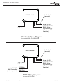
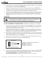
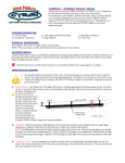
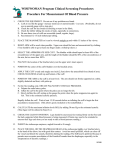
Installation Manual
M4 LED Controller
For SAVI Notes, SAVI Source & X-Stream LED Modules
NOTE TO INSTALLER
GIVE THIS MANUAL TO THE OWNER/OPERATOR AFTER INSTALLATION.
Model Numbers
M4-SA, M4-DMX, M4-RB
Nexxus Lighting, Inc. • 9400-200 Southridge Park Court • •Orlando, Florida 32819 •• 407.857.9900 • Fax 407.857.0050 • nexxuslighting.com
Wiring Diagrams
M4 Controller
Individual
Conduit
Connections
Up to 4 LED
ACCESSORIES
(SAVI Notes,
SAVI Source or
X-Stream LED
Modules)
120 or 240
VAC Power
Standard Wiring Diagram
for models M4-SA & M4-RB
M4 Controller
120 or 240
VAC Power
To SAVI 512
DMX Controller
(order separately)
DMX In
Individual
Conduit
Connections
Up to 4 LED
ACCESSORIES
(SAVI Notes,
SAVI Source or
X-Stream LED
Modules)
DMX Out
DMX Wiring Diagram
for model M4-DMX
Nexxus Lighting, Inc. • 9400-200 Southridge Park Court • •Orlando, Florida 32819 •• 407.857.9900 • Fax 407.857.0050 • nexxuslighting.com
Close Out
VIII. Close Out
1.
Locate the cover of the M4 controller and the installation hardware provided (screw
and flat washer).
2.
Check the gasket in the inside of the cover for damage and then turn the cover as
appropriate to orient the exterior silk-screened logos and/or lettering.
3.
Install the cover using the installation hardware. Torque each of the four screws to
12 in-lbs of torque maximum.
WARNING
Over tightening the screws on the cover will damage the case
and sealing system. This MAY allow water to penetrate into the
M4 controller and cause failure. If no torque screwdriver is
available, carefully tighten each of the four screws until a
medium level of “snugness” is achieved. The goal is to compress
the gasket without damaging the mounting flanges for the
cover screws.
THIS COMPLETES THE INSTALLATION OF THE M4 CONTROLLER. PLEASE SEE
THE QUICK PROGRAM GUIDE FOR A DESCRIPTION OF THE LIGHTING MODES AND
OPERATING INSTRUCTIONS.
9
Nexxus Lighting, Inc. • 9400-200 Southridge Park Court • •Orlando, Florida 32819 •• 407.857.9900 • Fax 407.857.0050 • nexxuslighting.com
System Testing (Cont.)
4.
Stand-alone (M4-SA) and Rainbow (M4-RB) units will come on to one of several lighting modes, but will always be “ON” when power is provided to the controller. By
toggling power, you can cycle through all of the modes.
Investigate the connections for any LED accessory that does not work correctly. It is
recommended that the colors be cycled until the “white” mode for this test. Please
note, that if power remains off for at least nine (9) seconds, the unit will store the last
mode and a “safety” white mode will be displayed on power up for 12 to 13 seconds
before the stored mode is recalled. Please consult the user manual for more detailed
operation instructions.
5.
Once testing is completed, power off the unit.
6.
Finally the DMX address should be set for M4-DMX units. The top
switch (S3) is the “hundreds” unit for the address, the middle switch
is the “tens” unit, and the lower switch (S1) is the “ones” unit. Addresses may be set from 1 to 501. This unit “uses” twelve addresses (so address 501 uses addresses 501 to 512 for example).
To set the unit to base address 127 set the S1, S2 & S3 switches as
follows (See FIGURE 4b):
Settings for Figure 4b
S3 -Top Switch = 1
S2 - Middle Switch = 2
S1 - Bottom Switch = 7
Set other address in a similar manner.
4
5
6
7
3
2
8
1
0
9
S3
4
5
6
7
3
2
8
1
0
9
S2
4
5
6
7
3
7.
8.
After cycling power to the unit again (with the new address on the
switches), the M4-DMX unit will now respond to standard DMX
commands (from the master controller) at the base address (LED
accessory #1 – red), up through the next eleven addresses (last address is LED accessory #4 – blue).
2
8
1
0
9
S1
FIGURE 4b
When satisfied the unit and installation are working properly, proceed to the “Close Out” section of this manual.
8
Nexxus Lighting, Inc. • 9400-200 Southridge Park Court • •Orlando, Florida 32819 •• 407.857.9900 • Fax 407.857.0050 • nexxuslighting.com
Table of Contents
I. Safety Precautions ......................................................2
II. Mounting ....................................................................3
III. Conduit and Ground Connections..............................3
IV. Internal Wiring............................................................4
V. LED Wiring Accessories . ............. ..............................5
VI. DMX Communication Bus Connections....................6
VII. System Testing..........................................................7
VIII. Close Out.................................................................9
1
Nexxus Lighting, Inc. • 9400-200 Southridge Park Court • •Orlando, Florida 32819 •• 407.857.9900 • Fax 407.857.0050 • nexxuslighting.com
Safety Precautions
READ AND FOLLOW ALL INSTRUCTIONS CAREFULLY
I. Safety Precautions
WARNING
1.
To prevent electrocution and/or death make sure power is off at the breaker.
2.
Avoid touching/installing the M4 controller box during electrical storms. Death
or serious injury may result due to lightning surges through the system.
3.
Be sure to check local electrical codes for grounding electrical boxes via
the approved method (internal conduit ground, external box ground wire to
grounding rod, Ground Fault Circuit Interrupt or GFCI, etc.)
4.
Use approved conduit routed by approved methods to conduit fittings on the
box.
5.
For DMX based units, do not install data cables in the same conduit as power
cables to prevent communication problems.
6.
Be sure the mounting surface is able to support the load of the controller. Use
all four mounting holes to secure the controller.
7.
There are no customer serviceable components inside the M4 controller. Only
qualified electricians should open the box for installation of the power and LED
accessories connections. All connections should enter through an approved
conduit method.
8.
LED accessories are low voltage and should never be electrically connected
to any power source other than the appropriate M4 controller connector (J5
to J8). Wires must be connected properly to avoid permanently damaging the
LED accessory.
Tools:
The following tools may be required to properly install the M4 controller
•
•
•
•
•
•
•
•
Screwdrivers (small 3/16” flat blade and medium sized phillips)
Digital Multi-meter (verifying power, and ground bond resistance)
Crescent wrench
Pliers
Carpenter’s level (to verify orientation of mounted enclosure)
Wire cutter (large enough to trim LED accessory cable #18AWG/4C)
Wire stripper #18 size
Box cutter or blade for removing outer sheath of LED accessory cable
Accessories:
The following items (standard electrician items) may be required to complete the electrical installation of the M4 LED controller
•
•
•
•
Wire nuts
Crimp lugs
Electrical tape
Tie wraps and adhesive tie wrap mounts
2
Nexxus Lighting, Inc. • 9400-200 Southridge Park Court • •Orlando, Florida 32819 •• 407.857.9900 • Fax 407.857.0050 • nexxuslighting.com
FIGURE 3c
System Testing
8.
If appropriate, repeat steps 3-7 for the DMX
output cable which should be attached to J4 of
the PCB.
J3
s
-
+
DMX (+)
Insert each wire into the appropriate terminal
block location. Using a small flat blade screwdriver, tighten each screw of the terminal block
until you feel it compress the wire and become
more difficult to turn. DO NOT OVERTIGHTEN.
Carefully pull on the wire to verify it is secure.
ble
7.
DMX IN
DMX (-)
The wires will be installed as shown to the right
in FIGURE 3c.
Shield Ca
6.
S = Shield Cable Wire
- = DMX(-) or Inverted Input
+ = DMX(+) or Non-Inverted Input
FIGURE 3c
VII. System Testing
Once all connections are completed, it is time to test the system.
Make sure all tools and loose items are removed from the controller and that no obvious
damage has occurred to the PCB before applying power to the unit. Do not skip the
grounding test mentioned earlier. It is imperative that a good system/safety ground be
provided to the system for the safety of all. Once satisfied that all appropriate preparations are complete, proceed to the steps below.
1.
2.
3.
To check the system it is necessary for someone to monitor
the output of a LED accessory or lamp during the power up sequence. Have one observer ready to see how the LED accessory
lights look during the initial power on.
M4-DMX units will have rotary switches on the PCB on the side
towards the power supply. Using a small screwdriver, set the following address on the switches (See FIGURE 4a).
After initial power up, M4-DMX units will enter a “power-on”
sequence consisting of (white, red, green, and blue) before
returning to a white output on all LED accessories. Investigate
the connections for any LED accessory that does not work correctly.
5
6
7
2
8
1
0
9
S3
Activate the circuit breaker or switch to provide power to the unit.
Settings for Figure 4a
S3 -Top Switch = 7
S2 - Middle Switch = 0
S1 - Bottom Switch = 1
4
3
4
5
6
7
3
2
8
1
0
9
S2
4
5
6
7
3
2
8
1
0
9
S1
FIGURE 4a
7
Nexxus Lighting, Inc. • 9400-200 Southridge Park Court • •Orlando, Florida 32819 •• 407.857.9900 • Fax 407.857.0050 • nexxuslighting.com
DMX Communication Bus Connections
7.
Repeat for the remaining three wires of the cable (see FIGURE 3b). Tuck the excess
cable out of the way for the remaining steps.
8.
Repeat steps 2-7 for LED accessory #2 using the appropriate conduit input for location #2 (usually the back most to the right side) and J6 of the PCB (see FIGURE 3b).
Note: Before cutting the cables for LED accessories #3 & #4 (steps 9-10),
verify the desired internal routing location to J7 & J8. Be sure to leave
enough cable to reach the appropriate terminal block.
9.
Repeat steps 2-7 for LED accessory #4 (it helps to install #4 before #3). Usually this
will be the front most conduit input to the right. Connect LED accessory #4 to J8 of
the PCB (see FIGURE 3b).
10. Repeat steps 2-7 for LED accessory #3. Connect LED accessory #3 to J7 (bottom
right) of the PCB (see FIGURE 3b).
Note: Using an adhesive backed, tie wrap mount helps locating the cables
for LED accessory #3 after tucking the cable for #4 along the right wall.
Vi. DMX Communication Bus Connections (on M4-DMX units)
Some M4 controllers use an optional serial communications bus (DMX bus) to communicate with a master controller. Some installations only require an incoming cable, while
other installations will require an input, as well as an output cable (proceeding on to the
next receiver/controller). This section details how to attach those connections.
1.
Determine if the installation uses an input, or both an input and an output DMX
connection. An additional output connection can be added in the future if desired.
2.
Locate the incoming DMX communication cable (see FIGURE 2). This cable will be
attached to terminal block J3 on the PCB. Trim excess cable leaving no more than
four (4) inches protruding from the conduit.
3.
Carefully remove one and one-half (1-1/2) inches of insulation from the cable. The
cable is a twisted shielded pair type, so be careful to not damage the shield or the
internal wires.
4.
Locate the actual shield “cable” within the overall “shield” (see FIGURE 3d) and
separate it from the individual shield wires. Carefully cut off and remove the shield
wires but NOT the small shield cable (see FIGURE 3d).
DMX (+) / DMX(-)
wires stripped
DMX COMMUNICATION CABLE
DMX (+) / DMX(-) wires
Shield Cable
DMX Communication
cable
FIGURE 3d
5.
Using the wire stripper, remove 1/8 to 3/16” of insulation from each of the remaining
two wires.
6
Nexxus Lighting, Inc. • 9400-200 Southridge Park Court • •Orlando, Florida 32819 •• 407.857.9900 • Fax 407.857.0050 • nexxuslighting.com
Mounting Instructions
INSTALLATION INSTRUCTIONS
II. Mounting
1.
Select a mounting location so that the bottom
surface of the enclosure will be at least twelve
(12”) inches above the ground (See FIGURE 1).
Be sure to provide enough clearance below the
box to route the power, communications, and
LED accessory conduits as desired.
2.
Place the controller at the location desired and
mark the location of the upper two mounting
holes.
3.
Drill holes as appropriate (wood, masonry block,
brick, etc.) for the mounting hardware. Be sure to use a mounting method that
can withstand the weight of the controller and the attached conduits.
4.
Temporarily secure the box to the mounting surface using the method selected.
5.
Mark the position of the lower two holes, remove the box, drill the lower two
holes, and prepare the lower mounting locations.
6.
Secure the four mounting screws or bolts to complete the mounting of the M4
controller.
12”
above
ground
minimum
FIGURE 1
WARNING
Due to the desired water resistant seal of the enclosure, do not remove any knockouts unless that hole will have a conduit installed.
If a knockout is accidentally removed, steps must be taken to REseal the opening or the M4 controller will be damaged.
III. Conduit and Ground Connections
1.
2.
3.
After selecting the desired conduit
size (½” or ¾”), carefully remove
the appropriate “knock outs” in the
bottom of the enclosure while being
careful not to touch the PCB (Printed
Circuit Board).
LED ACCESSORY #3
(J7)
LED ACCESSORY #4
(J8)
DMX OUT
A/C Service
conduit IN
DMX IN
Install the power, communication,
and LED accessory conduit fittings
as desired to the enclosure (see
FIGURE 2).
LED ACCESSORY #1
(J5)
LED ACCESSORY #2
(J6)
FIGURE 2
Note: The left most conduit fitting hole must
be used for installation of power to the controller. The LED accessory and communications conduit connections should be placed
as shown in FIGURE 2.
Pull cables through to the ends
of the conduit. Leave extra cable
length to allow preparation and
installation of the wires.
3
Nexxus Lighting, Inc. • 9400-200 Southridge Park Court • •Orlando, Florida 32819 •• 407.857.9900 • Fax 407.857.0050 • nexxuslighting.com
Internal Wiring
4.
Install the ends of the conduit to the enclosure after routing the excess wire length
into the enclosure at the appropriate locations (see FIGURE 2)
5.
If required by the local electrical codes or as desired, install a ground wire directly to
the enclosure using the external ground connection provided (not shown).
See FIGURE 4a
page 7
See FIGURE 3b
page 5
PCB - PRINTED
CIRCUIT BOARD
J8
POWER
SUPPLY
J7
J3
See FIGURE 3a
page 4
J4
J5
J6
See FIGURE 3c
page 7
FIGURE 3
IV. Internal Wiring
POWER PIG-TAIL CONNECTION
To M4
Power Supply
A/C Connections
1.
Locate the power pig-tail provided with the M4 controller.
It will be located under the power supply and will consist
of one black (120 or 240 VAC), one white (neutral), and one
green (safety ground) wire.
2.
Locate the incoming power wires from the conduit.
3.
Trim excess lengths as desired and strip back approximately 3/8” of the insulation from all wires.
4.
Twist the black wire of the M4 controller with the incoming
“120 or 240 VAC” wire. Install a wire nut or crimp using an
approved insulated method (see FIGURE 3a).
4
A/C
Line
(Black)
To Ground
A/C
Neutral
(White)
A/C
Ground
(Green)
From A/C Input
Conduit
FIGURE 3a
Nexxus Lighting, Inc. • 9400-200 Southridge Park Court • •Orlando, Florida 32819 •• 407.857.9900 • Fax 407.857.0050 • nexxuslighting.com
LED Accessory Connections
5.
Twist the white wire of the M4 controller with the incoming “neutral” (not the ground)
wire. Secure as in “step (4)” (see FIGURE 3a).
6.
Repeat for the green ground wire and the incoming ground wire (see FIGURE 3a).
7.
Carefully tuck the wires into the area below the power supply while being careful that
the wires do not lay against the internal components of the power supply.
8.
If possible, verify a grounding path exists between the incoming service ground wire
and the case of the M4 controller. If this is not possible, double check the ground
connection between the crimp and/or wire nut connection and the case of the M4
controller.
WARNING
Due to the desired water resistant seal of the enclosure, do not remove any knockouts unless that hole will have a conduit installed.
If a knockout is accidentally removed, steps must be taken to REseal the opening or the M4 controller will be damaged.
V. LED Accessory Connections (SAVI Notes, SAVI Source or X-Stream)
1.
Locate the incoming cable for LED accessory #1 (see FIGURE 2). This cable will be
attached to terminal block J5 on the PCB. Trim excess cable leaving no more than
six (6) inches protruding from the conduit.
2.
Carefully remove two (2) inches of insulation from the cable (a box cutter set to protrude less than 1/8” is good for this purpose). Cut from the desired removal location
towards the cut end of the cable to prevent damaging the internal wires.
3.
Separate the insulation along the cut path and fold it back. Using cutters remove the
excess cable insulation. Only the four internal wires should be remaining (red, green,
blue, and a fourth conductor - usually black).
4.
Using the wire stripper, remove 1/8 to 3/16” of insulation from each of the four wires.
5.
The wires will be installed as shown in FIGURE 3b below.
LED ACCESSORY CONNECTION TO TERMINAL BLOCKS
(J5, J6, J7 & J8)
B
Position + = Power Wire (usually Black)
Position R = Red wire
Position G = Green wire
Position B = Blue wire
G
R
+
LED outputs must be connected as
shown to avoid damage to the circuit
FIGURE 3b
6.
Insert each wire into the appropriate terminal block location. Using a small flat blade
screwdriver, tighten each screw of the terminal block until you feel it compress the
wire and become difficult to turn (approximately 3.5 in-lbs).
DO NOT OVERTIGHTEN. Carefully pull on the wire to verify it is secure.
5
Nexxus Lighting, Inc. • 9400-200 Southridge Park Court • •Orlando, Florida 32819 •• 407.857.9900 • Fax 407.857.0050 • nexxuslighting.com
LIMITED WARRANTY
Nexxus Lighting, Inc. warranties its products, excluding lamps, to be free from defects in material and/or
workmanship, under normal condition, use and service, for a period of two (2) years from the original
invoice date (Five (5) Years for Red, Amber and Orange FlexLED and Border Light LED products and
one (1) Year for Non-UL Listed Power Supplies). If proof of purchase is provided, Nexxus Lighting will
warranty the product for two (2) years from date of the purchase (Five (5) Years for Red, Amber and
Orange FlexLED and Border Light products and one (1) Year for Non-UL Listed Power Supplies).
TERMS AND CONDITIONS:
This warranty only applies when Nexxus Lighting products are properly wired and installed together as
a system; and operated within the electrical values shown on the Nexxus Lighting specification sheets;
used in lighting equipment designed and approved for the application and environmental conditions
(temperature, humidity) within the normal specified operating range of the system. This warranty does
not apply to any abnormal use in violation of any applicable standard, code or instructions for use in
installations including those contained in the latest National Electrical Code (NEC), the Standards for
Safety of Underwriters Laboratory, Inc. (UL), Standards for the American National Standards Institute
(ANSI), in Canada, the Canadian Standards Association (CSA), Europe (CE), Australia (C-Tick). This
warranty will not apply in the event of conditions demonstrating abnormal use or stress, including
under/over voltage conditions, excessive switching cycles, excessive operating hours, alterations,
accident, theft, misuse, abuse and damaged caused by negligent installation, improper maintenance
or where adequate care has not been taken to prevent damage to the lighting system. Replacement of
Nexxus Lighting components with any other manufacturer will void the entire warranty.
WARRANTY SERVICE CLAIMS:
Nexxus Lighting must issue a Return Material Authorization (RMA) number for all requests for warranty
review. To expedite service, please contact Nexxus Lighting Customer Representative: 407-857-9900.
If you are unsure whether a situation exists that is covered by this warranty, please contact Nexxus
Lighting Customer Service for assistance. In the event of a defect in material or workmanship during
the warranty period, Nexxus Lighting will repair or replace (at its own discretion) its products under the
conditions of the warranty.
RETURN OF DEFECTIVE PRODUCT:
After contacting Nexxus Lighting and receiving the RMA#, the purchaser / user shall promptly return
the product after receiving instructions regarding if, when and where to ship product. Product must be
returned within 30 days of receiving RMA#, Shipping box must be clearly marked with RMA#. Failure to
follow this procedure shall void this warranty. Nexxus Lighting will cover expenses for material but will
not cover shipping costs. Products returned without an RMA# will be refused and returned to sender at
the senders expense.
REPLACEMENT OF PRODUCT, LIMITS OF LIABILITY:
The foregoing shall constitute the exclusive remedy of the purchaser and the sole liability of Nexxus
Lighting regarding its products and component warranty. NO WARRANTY OF MERCHANTABILITY OR
FITNESS FOR A PARTICULAR PURPOSE IS MADE OR IS TO BE IMPLIED. In no event shall Nexxus
Lighting be liable for any other costs or damages including labor charges, lost profits or revenues,
incidental, special or consequential damages. Total liability shall not exceed the total extended purchase
price for the product. Nexxus Lighting reserves the right to examine all failed Nexxus Lighting products
and components to determine the cause of failure and patterns of usage and reserves the right to be
the sole judge as to whether any product or component is defective and covered under this warranty.
May 4, 2007 Rev. 0
31.0013, Revision “B”
©2006-2007 Nexxus Lighting, Inc.
MAN.M4.0807.V02.01