1
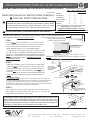
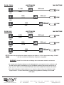
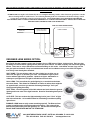
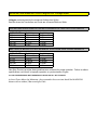
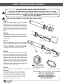
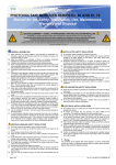
INSTALLATION AND USERS GUIDE
2014 MINI MELODY (COLOR)
2013/14 SAVI MELODY (COLOR)
2013/14 SAVI SOL (COLOR)
2014 MINI BLANCO (WHITE)
2013/14 SAVI BLANCO (WHITE)
2013/14 SAVI BLANCO PRO (WHITE)
IMPORTANT WARNING & SAFETY INSTRUCTIONS
DANGER - SERIOUS BODILY INJURY OR DEATH CAN RESULT IF THESE
LIGHTS ARE NOT INSTALLED AND USED CORRECTLY
DANGER - INSTALLERS, POOL OPERATORS AND POOL OWNERS MUST
READ THESE WARNINGS AND ALL INSTRUCTIONS BEFORE USING
THESE LIGHTS
WARNING - Before installing this product, read and follow all warning
notices and instructions in this Guide. Failure to follow warnings and
instructions can result in severe injury, death or property damage. For
more information contact company at numbers contained within Guide.
WARNING - These underwater swimming pool lights MUST BE installed by a
licensed or certified electrician or a qualified pool professional in accordance with
the National Electric Code (NEC) or the Canadian Electric Code (CEC), CSA C22.1.
All applicable local installation codes and ordinances must also be adhered to.
Improper installation will create an electrical hazard which could result in death or
serious injury to pool users, installers or others due to electrical shock.
ALWAYS DISCONNECT THE POWER TO THE POOL LIGHT(S) BEFORE SERVICING.
IMPORTANT NOTICE - ATTENTION INSTALLER: This Installation and
Users Guide contains important information about the installation,
operation and safe use of this swimming pool/spa light. This Guide
should be given to the owner and/or operator of this equipment.
READ AND FOLLOW ALL INSTRUCTIONS
SAVE THESE INSTRUCTIONS
Products in this Guide are covered
under one or more of the following
patents: 6,827,464 7,244,037 6,971,760
5,617,496 5,617,497 5,789,471
5,528,714 5,33,228 6,200,012
6,48,952 6,422,730 6,367,100
6,398,397 6,393,192 6,375,342
7,204,602 7,229,027
DOES NOT APPLY TO THE P SERIES
OF LIGHTS
9400 Southridge Park Ct #200 Orlando FL 32819
Tel: 407.855.5630
Fax: 407.210.8679
nextstepproduct.com
The following are registered
trademarks and designs of
Next Step Products: Savi,
Endglow, Sideglow Oasis
INSTALLATION INSTRUCTIONS-2013/14 SERVICABLE PRODUCT
MINI MEL/MINI BLANCO/MELODY/BLANCO/BLANCO PRO/SOL Underwater LED Lights
WATTS
Product Names
READ AND FOLLOW ALL INSTRUCTIONS CAREFULLY
CAUTION! SAFETY PRECAUTIONS
SAVI Lights are a low voltage light and should NEVER be electrically
connected to a power source other than an approved pool “Safety Rated”
UL Listed outdooor rated Class 3,12VAC Transformer. Failure to comply
will either damage or destroy SAVI Lights and VOID the Warranty.
TURN OFF MAIN POWER TO LIGHT BEFORE INSTALLATION /SERVICE
AMPS
MINIMUM CONDUIT
REQUIREMENTS
MINI MEL
6
.5
3”
MINI BLANCO
5
.42
3”
SAVI-MELODY
14
1.2
9”
MELODY BLANCO
10
0.83
9"
BLANCO PRO
20
1.67
14"
SAVI SOL
28
2.3
14"
All products listed above come in a variety of cord length
Typical Lengths are: 30-50-100 & 150FT
LIGHTS ARE SERVICABLE - DO NOT
REMOVE ENCLOSURE/CORD FROM CONDUIT
NOTE: No separate ground or bonding wire is required for
NOTE: For Vinyl wall Fittings use both rubber
the Melody, Blanco, Blanco Pro or SOL low voltage lights which gaskets. For Gunite and Fiberglass remove
the Small gasket and use the Large one only.
have no exposed metal. They do not require a niche.
For Replacement LED Light Cartridges
see Light Cartridge Replacement Page
STEP 1
The light
must be installed in or on a wall of the pool (or
water feature) with the top of the lens opening not less than 4
inches (10.16cm) below the normal water level of the pool.
4” MIN. FROM WATER
LEVEL TO TOP OF LENS
1” min. Pipe
Sweeps ONLY
No 90 degree bends
1.5” Pipe
1.5” THREADED WALL FITTING
NOTE: Check with Local Building officials as to what conduit/pipe is acceptable
Allow 18” - 24”
slack for
Service Loop
STEP 2
Snake the 2-conductor electric cord through the conduit outlet
of the wall
into the conduit and up to the location of the
12VAC pool transformer. Cut off excess cord after allowing for
service and length of run to the transformer. Pull the
snug
to the wall
18"-24" of excess cord recommended as service loop.
12VAC Pool Transformer
NOTE: Service
Loop not applicable
for Junction Box
Installations.
4” MIN. FROM WATER
LEVEL TO TOP OF LENS
NOTE: Make sure all protective coverings have been removed.
Conduit to 12VAC transformer
Winterization Clause
Pool Water Level must be drained down 12” below light(s) position in pool wall. We
recommend that the lights be loosened from their wall fitting to allow drainage of water
that might have accumulated within conduit. Consult your local Swimming Pool
Professional for proper local area winterization processes. At NO TIME should water be
removed from the pool without checking ground water tables.
STEP 3
Using enclosed Lens Key, thread the light into the wall fitting until it is
snug. Please provide Pool Owner with minimum of 1 key upon job
completetion (see winterization clause above)
An example of an approved pool transformer is the Intermatic model PX-100 or PX-300.
Refer to WIRE GAUGE AND WIRE LENGTH guide for for proper wire gauge size in
reference to the use of Junction Boxes installations. NOTE: SAVI Lights can be used
with any UL Listed outdoor rated Class 3, 12VAC transformer provided the wattage and
amperage is not exceeded by the total wattage and amperage in use.
A Division of Next Step Products
Large Gasket
Flat Gasket
NOTE: Requires the use of a 1-1/2” threaded wall fitting.
1.5” Pipe through bond beam for a minimum of 14” then 1” conduit
min. with sweeps / no 90 degree bends. We highly recommend
the use of 1.5" pipe throughout the entire width of the bond beam.
NOTE: Use of 1.5” pipe with 14” min. length will accommodate all
SAVI Lighting nicheless products. See Minimum Conduit
Lengths listed above.
Small Gasket
4” MIN. FROM WATER
LEVEL TO TOP OF LENS
Vertical Installation for
Benches, Swimouts and
Fountains
Tighten
9400 SOUTHRIDGE PARK COURT SUITE 200
ORLANDO, FLORIDA 32819 USA
Tel: 407.855.5630
Fax: 407.210.8679
nextstepproduct.com
OPERATION INSTRUCTIONS
Synchronization Process for Savi LED Color Pool and Spa Lights
Important Note: A
ll fixtures must be tied into the same transformer, circuit or switch for synchronization
to occur.
LIGHT SYNCHRONIZATION
urnthelightsonandwaitfor20seconds.Thelightswillfirst comeonwhitefor10-15secondsandthenreturntothe
1. T
color mode it was on prior to being turned off. (If this is the initial installation, the lights will return to whatever mode
they were in when last receiving power).
2. Do not move to the next step until step one is complete.
3. T
osynchronizelights,turnthelightsoff,wait6-9secondsandthenturnthembackon.Youshouldseethreequick
flashes (red,green&blue),andthenallthelightswillresettothefirst colormode(TreasureIsland).
4. (A) If you do not see three quick flashes then the lights did not reset.
(B) If you did not wait long enough (shorter than 6 seconds) the lights will advance to their next color mode. They are
not synched as each light could be in different color modes.
(C) If you wait too long (longer than the 9 seconds) they all will go to white for 10-15 seconds, looking like they’re
synched BUT AFTER 15 seconds they will return to their previous color mode (which at this point the lights are
still unsynchronized).
5. Repeat step1 - 3 until synchronization is accomplished.
6.
To confirmthelightshavebeensynchronized(TreasureIslandMode)-thebestwayisto:turnthelightsofffor1-2
seconds and turn back on – DO THIS TWICE. All the lights should be in the SAVI BLUE color mode. If they are all
fixedonBLUE–youhavenowsynchronizedyourlights.Ifnot–turnthelightsoffformorethan20seconds–Turn
back on and proceed to Step 1.
OPERATING THE LIGHT
omovetothenextcolormode,Turnthelights offfor1-2secondsandturnbackon.Repeatuntildesiredcolormode
7. T
is found.
Example: If you followed step six and are now on SAVI Blue and want the lights to be White, then the lights must be
turned off and on (7) seven times to bring you to Moonlight White.
1.
2.
3.
4.
5.
6.
7.
8.
9.
Treasure Island / Slow color change
Moonlight White / Fixed White
SAVI Blue / Fixed Blue
Sargasso Sea / Fixed Green
Blue Lagoon / Fixed Light Blue
Passion Pink / Fixed Magenta
Caribbean Hues / Blue and Green Slow Color Change
Copacabana / Magenta, Yellow and Orange Slow Color Change
Dance party / Multi Color Strobe Effect
8. T
he lights have memory. If the lights are off for 10 seconds or more, the next time the lights are turned on, they will
go to white for approximately 10-15 seconds and then return to the last color mode they were on prior to being turned
off (Step 1 listed above). This function allows you to keep your lights returning to your favorite color mode every time
the lights are turned back on.
If you have internet access, please go to www.nextstepproduct.com/SAVI/support.html and click on the link under USER
GUIDES that says “synchronous process” for a video that demonstrates how this process works.
A Division of Next Step Products
9400 SOUTHRIDGE PARK COURT SUITE 200 ORLANDO, FLORIDA 32819 USA
Tel: 407.855.5630 Fax: 407.210.8679 nextstepproduct.com
IMPORTANT: READ FIRST
SAVI LED UNDERWATER LIGHTS ARE LOW VOLTAGE FIXTURES. IMPROPER
WIRE GAUGE AND WIRE LENGTH CAN AFFECT THE PERFOMANCE OF THESE
PRODUCTS. FOLLOW THE GUIDES BELOW TO DETERMINE THE PROPER
OPERATION AND OPTIMUM PERFORMANCE OF SAVI LIGHTS.
!
WIRE GAUGE & WIRE LENGTH GUIDE
NOTE: Min. 12VAC: / Max 13VAC. The maximum run of service between transformer and lights should not
exceed 150ft in total length, inclusive of the use of J Box or not.
When J-Box used all voltage readings are to be taken at J-Box when all Lights are set on WHITE.
When Lights are connected directly to transformer, voltage readings are taken at transformer with Lights on WHITE.
LOW VOLTAGE (12VAC) TRANSFORMER
JUNCTION BOX
PX100 or PX300
Black Hot Line
White Neutral
Green Ground
BLK
BLK
WHT
WHT
Crimp Style Connectors Crimp Style Connectors
Recommended
Recommended
NOTE: This Diagram is to be used as a guide line only for a typical System Installation and should only be used
as such. It is the Installers sole responsibility to verify and assure that proper gauging of secondary wiring
from the Transformer to the J-Box are in compliance with your local, State and National Electrical Codes.
NOTE: The use of Solid Core over Stranded wire and terminating at Bus Bars is strongly recommended.
JUNCTION BOX
BUS BAR
PX100 / PX300
T
0-50ft
100ft cord
JB
12GA
MAX WATTAGE
168W
12V
T
100ft
JB
10GA
50ft cord
126W
12V
130ft
T
8GA
JB
20ft cord
98W
12V
JUNCTION BOX
BUS BAR
PX100 / PX300
A Division of Next Step Products
MAX WATTAGE
9400 SOUTHRIDGE PARK COURT SUITE 200 ORLANDO, FLORIDA 32819 USA
Tel: 407.855.5630 Fax: 407.210.8679 nextstepproduct.com
0 - 50ft
100ft cord
210W
8GA
12V
JUNCTION BOX
BUS BAR
PX100 / PX300
T
0 - 50ft
100ft cord
JB
12GA
MAX WATTAGE
210W
13V
T
100ft
JB
10GA
50ft cord
168W
13V
130ft
T
JB
8GA
20ft cord
136W
13V
JUNCTION BOX
BUS BAR
PX300 ONLY
T
0-50ft
100ft cord
JB
12GA
MAX WATTAGE
240W
14V
T
100ft
10GA
JB
50ft cord
224W
14V
T
130ft
8GA
JB
20ft cord
182W
14V
NOTE: Please use appropriate low voltage supply to pool lights, ie. if 12V is appropriate voltage DO NOT
SAVI Pool and Spa | 9400 Southridge Park Court Suite 200 | Orlando | Florida | 32819 | USA | T. 407.855.5630 nextstepproduct.com
use 13V or 14V tap on transformer output (if so equipped),
WARNING - DO NOT run 120V and Low Voltage wires in the same conduit or enclosures.
ALL Savi LED Colored Lights including Savi Color LED Light Drivers are designed to work or synchronize with
each other. Please follow all installations for proper installation and follow Sychronization Instructions for
proper operation. OUR SAVI STANDARD LED LIGHTS WILL NOT WORK WITH P SERIES LED LIGHTS
All Savi White LED Lights and White LED Drivers are designed to allow for the option of dimming or light
output reduction. See enclosed information regarding general guidelines for dimming of our Savi LED
White Lights.
A Division of Next Step Products
9400 SOUTHRIDGE PARK COURT SUITE 200 ORLANDO, FLORIDA 32819 USA
Tel: 407.855.5630 Fax: 407.210.8679 nextstepproduct.com
THE FOLLOWING INFORMATION IS FOR GENERAL INSTALLATION OF DIMMING SWITCHS OR CONTROLS FOR USE
WITH SAVI BLANCO, MINI BLANCO, BLANCO PRO WHITE LED LIGHTS. THIS INCLUDES BLANCO PRO WHITE LED
LIGHT DRIVERS.
All WHITE LED Savi Lights can be dimmed by the use of simplistic dimming switches. These directions specify those switches
that are for independent or stand a lone use. For achieving dimming by the use of automatic or home based energy control
systems please consult those controls systems instructions. AT NO TIME SHALL ANY SWITCH OR CONTROL BE
INSTALLED ON THE 12V SIDE OF THE TRANSFORMER IN AN ATTEMPT TO DIM LIGHTS. DOING SO MAY DAMAGE
THE LED LIGHT CARTRIDGE AND VOID WARRANTY.
LOW VOLTAGE TRANSFORMER
White Neutral
Black Hot Line
PX100 or PX300
Dimmer Switch installed in
proper electrical enclosure
Black Hot Line
White Neutral
Green Ground
BLK
BLK
WHT
WHT
Crimp Style Connectors
Crimp Style Connectors
Recommended
Recommended
DESIGNER LENS SERIES OPTION:
Savi Pool & Spa has created a unique set of options for our LED Series of lights - designer lens. Each one has
the ability to create fantastic lighting effects within the pools interior. No other company can offer these lighting
effects. These are so unique that we have a Patent Pending on this series. Look below and see if any one fits
into your pool environment. Keep in mind that these lenses can be added on to any of our 2013 LED Lights even if they have already been installed.
HALF DOME - This escutcheon adds over the existing lens to allow you to
direct 1/2 the light in a direction you want. Downwards-to light a pools
interior without light shining upwards. Upwards to light a waterfeature or
sideways to put light where it might be needed but no where else
HALO LENS - This lens allows for gentle lighting in an area but knocks down
the center beam. This allows for installation on walls, etc where there might be
an opposite wall, etc where you want to eliminate generating a "hot" spot.
Great general lighting but softly.
SPOT LENS - Just the opposite of the Halo whereas we knock down the general
lighting and focus more of the light forwards. Great for illuminating that special
feature.
CATS EYE - This lens reduces the light eminating but for just a "slice" of light
that is broad but thin. An incredible effect for illuminating but without spilling
light all over.
DIAMOND - WOW want to really create something special? The Diamond lens
creates incredible points of light throughout the interior. The points will be
different the farther away from the light they are. Put the LED colored light on
DANCE PARTY MODE AND WATCH THE FUN BEGIN!
9400 SOUTHRIDGE PARK COURT, SUITE 200, ORLANDO, FL 32819 USA
TEL: 407.855.5630 FAX: 407.210.8679
nextstepproduct.com
Minumum and Maximum Cord Lengths Per Voltage Input
Voltages are determined by the measured Voltage level @ the
Bus Bar where the Transformer and Cords are connected while on White
MINI MEL/MINI BLANCO/MELODY/BLANCO MIN/MAX VOLTAGE PER CORD LENGTH
CORD LENGTH
15 Feet
30 Feet
50 Feet
100 Feet
150 Feet
Min. Voltage
7.8Vac
8.6Vac
9.4Vac
10.7Vac
11.82V
Max. Voltage
12.0Vac
12.2Vac
12.4Vac
13.2Vac
13.8Vac
MEL-SOL & BLANCO PRO MIN/MAX VOLTAGE PER CORD LENGTH
CORD LENGTH
20 Feet
30 Feet
50 Feet
100 Feet
150 Feet
Min. Voltage
9.8Vac
9.92Vac
10.34Vac
10.9Vac
11.43Vac
Max. Voltage
12.0Vac
12.2Vac
12.56Vac
13.5Vac
14.1Vac
Next Step Products provides these guidelines as a reference for proper operation. Failure to adhere
specifications could result in improper operation or synchronization of lights.
ALL VOLTAGE READINGS ARE TAKEN WHILE LIGHTS ARE ALL SET TO WHITE
As these Charts address the Minimum - please remember that at no time should the MAXIMUM
distance with or without J Box extend past 150 ft.
2013/14 SAVI LED LIGHTING PRODUCTS
BASIC TROUBLESHOOTING GUIDE - FOR ADDITIONAL INFORMATION CONTACT
TECHNICAL SERVICES AT TELEPHONE NUMBERS LISTED BELOW
ALL LIGHTS FAIL TO ILLUMINATE - Check 120V power supply into transformer - Check for 12V
output at transformer - check or reset GFCI. Make sure 120 volts has not been used in the
installation of these lights - damage is assured and is NON WARRANTY.
ONE OR MORE LIGHTS DIM - This is generally caused by a poor connection or improper wire
gauge. To determine if light or lights has fault - separate each light from all other lights and
independently wire 12V to this light only. Repeat process on each light. If junction box is used recheck for proper connection of light cord. AGAIN IF A JUNCTION BOX IS BEING USED - VERIFY
THAT THE CORRECT WIRE GAUGE IS BEING USED BETWEEN TRANSFORMER AND JUNCTION BOX.
EVEN THOUGH OTHER LIGHTS MIGHT WORK CORRECTLY - IMPROPER WIRE GAUGE SIZE COULD
ALLOW 1 OR MORE LIGHTS TO WORK IMPROPERLY. Measure and verify that proper low voltage is
being supplied to lights - see WIRE GAUGE & WIRE LENGTH GUIDE CHART.
BLINKING, FLASHING, NON WORKING LIGHTS - This is generally caused by a poor connection
or improper wire gauge. To determine if light or lights has fault - separate light from all other lights
and independently wire 12V to this light only. Repeat process on each light. If junction
box is used - recheck for proper connection of light cord. AGAIN IF A JUNCTION BOX IS BEING
USED - VERIFY THAT THE CORRECT WIRE GAUGE IS BEING USED BETWEEN TRANSFORMER
AND JUNCTION BOX. EVEN THOUGH OTHER LIGHTS MIGHT WORK CORRECTLY - IMPROPER
WIRE GAUGE SIZE COULD ALLOW 1 OR MORE LIGHTS TO WORK IMPROPERLY. Measure and
verify that proper low voltage is being supplied to lights - see WIRE GAUGE & WIRE LENGTH
GUIDE CHART. MOST IMPORTANTLY SEE CHART FOR MIN/MAX VOLTAGE & CORD
LENGTH CHART.
COLORED LIGHTS OUT OF SYNCH - Follow Synchronization Instructions in this Guide. Be very
patient and read instruction carefully. If lights fail to synchronize - verify that proper wire
connections are being achieved for those lights that are out of step with others. Generally a lights
failure to sync with the rest is: improper voltage supply or poor connection to light.
NOTE: In most situations problems come down to 4 main faults: improper voltage supply,
improper wiring gauge,improper/poor wiring connections or the light itself.
2013/14 SAVI LED LIGHTS ARE FIELD SERVICABLE AND THE CORD AND LIGHT BODY
FIXTURE SHOULD NOT BE REMOVED COMPETELY FROM THE CONDUIT OR POOL. THERE SHOULD
BE ENOUGH CORD SUPPLIED IN THE SERVICE LOOP TO REMOVE LIGHT FROM WALL FITTING AND
LIFTED ABOVE WATER LEVEL FOR LED LIGHT CARTRIDGE REPLACEMENT. IF THERE IS NOT
ENOUGH CORD IN SERVICE LOOP OR IT CANNOT BE ACCESSED - POOL WATER CAN BE DRAINED
BELOW LIGHT TO ACCESS FRONT OF LIGHT.
DO NOT PULL LIGHT AND CORD ENTIRELY FROM CONDUIT UNLESS INSTRUCTED BY COMPANY.
SAVI POOL AND SPA WILL NOT ACCEPT ENTIRE LIGHTS BEING RETURNED FOR SERVICE
UNLESS INSTRUCTED BY COMPANIES TECHNICAL SERVICES DEPARTMENT
ONLY LED LIGHT CARTRIDGES SHOULD BE REPLACED OR EXCHANGED WITH THE
2013/14 PRODUCT
Refer to the Light Cartridge Replacement Instructions included in this Guide for light replacement.
WARNING: All servicing of Savi LED Lights should be done by a licensed or certified electrican or a
qualified pool professional in accordance with the National Electric Code (NEC) or Canadian Electric
Code (CEC)
For additional troubleshooting assistance or installation advice please contact Technical
Services at telephone number below.
9400 SOUTHRIDGE PARK COURT, SUITE 200, ORLANDO, FL 32819 USA
TEL: 407.855.5630 FAX: 407.210.8679
nextstepproduct.com
LIGHT CARTRIDGE REPLACEMENT
LED LIGHT FIXTURES SHOULD NEVER BE ELECTRICALLY
CONNECTED TO A POWER SOURCE OTHER THAN AN APPROVED POOL “SAFETY" UL LISTED
OUTDOOR RATED CLASS 3, 12VAC TRANS-FORMER. THE SAVI NOTE SHOULD ONLY BE CONNECTED
TO THE SAVI M4 CONTROLLER. FAILURE TO COMPLY WILL EITHER DAMAGE OR DESTROY THE LIGHT
FIXTURE AND VOID THE WARRANTY.
TURN OFF MAIN POWER TO LIGHT BEFORE INSTALLATION
STEP 1
Fixture Body
TURN OFF MAIN POWER TO LIGHT BEFORE
REPLACING LIGHT CARTRIDGE. Be sure the
light fixture is in a dry environment. Remove the (8)
eight screws from the lens with the tool provided.
Pull the lens from the fixture body. Remove and
discard the O-ring between the Lens and Fixture
Body.
O-Ring
Lens
STEP 2
Using the tool provided, insert and turn the threaded portion into the extraction hole in the face of the
Light Cartridge. Pull the Light Cartidge from the
housing body.
Extraction Tool /
Screw Driver
Light Cartridge
STEP 3
Insert the replacement cartridge into the housing
body. Line up the TAB at the end of the circut board
with the receiving slot inside the housing body.
It may be necessary to slowly turn the Light
Cartridge until the TAB lines up with the SLOT.
SLOT
STEP 4
Clean the Lens and the Enclosure of any remaining
old Silicone before applying new Silicone and replacing the Lens. Replace the O-ring with the new one
provided. Attach the lens onto the fixture body.
Tightly secure the eight (8) screws indicated in the
diagram to the right. Once all screws are tight, slowly
submerse in water, checking for any air bubbles quickly remove from water bubbles appear as it
indicates the seal is not water tight. Retighten the
screws and test for bubbles again.
STEP 5
Reset the fixture into the wall fitting and turn the power ON.
TAB
Replacement
Light Cartridge
New O-Ring
2
3
5
8
SILICONE BEAD ON LENS
Apply a new silicone bead to
the lens with tube provided
after cleaning the lens and
body of old silicone.
7
6
4
1
SCREW TIGHTENING DIAGRAM
WINTERIZING
REPLACEMENT LIGHT CARTRIDGE KIT PART NUMBERS
MELODY-CARTRIDGE-KIT
BLANCO-CARTRIDGE-KIT
BLANCOPRO-CARTRIDGE-KIT
SOL-CARTRIDGE-KIT
LC111912
The water level should be lowered to approximately 12
inches below the pool lights, make certain the water is
drained out of the wall housing. Consult a Local Swimming
Pool Professional for proper winterization. Minimum
safeguard requires dropping the water level 2”-4” below
the light. At NO TIME should there be water removed from
the pool without checking ground water tables.
9400 Southridge Park Court Suite 200 Orlando, Florida 32819 USA T. 407.855.5630 NextStepProduct.com
LIMITED PRORATED WARRANTY
TERMS AND CONDITIONS:
ThiswarrantyonlyapplieswhentheCompany’sproductsareproperlywiredandinstalledtogetherasasystem;
andoperatedwithintheelectricalvaluesshownontheCompany’sspecification sheets;usedinlightingequipment
designedand approved for the application and environmental conditions (temperature, humidity) within the normal
specified operatingrangeofthesystem.Thiswarrantydoesnotapplytoanyabnormaluseinviolationofanyapplicable
standard,codeorinstructionsforuseininstallationsincludingthosecontainedinthelatestNationalElectricalCode
(NEC),theStandards for Safety of Underwriters Laboratory, Inc. (UL), Standards for theAmerican National
Standards Institute(ANSI), in Canada, the Canadian StandardsAssociation ( CSA), Europe (CE),Australia (CTick).This warranty willnot apply in the event of conditions demonstrating abnormal use or stress, including
under/over voltage conditions,excessiveswitchingcycles,excessiveoperatinghours,alterations,accident,theft,
misuse,abuseanddamagedcausedbynegligentinstallation,impropermaintenanceorwhereadequatecarehasnot
beentakentopreventdamagetothelightingsystem.ReplacementoftheCompany’sproductcomponentswithany
othermanufacturerwillvoidtheentirewarranty.
WARRANTY SERVICE CLAIMS:
The Company must issue a Return Material Authorization (RMA) number for all requests for warranty review. To expedite
service, please contact the Company’s Customer Representative where you purchased the product. If you are unsure
whether a situation exists that is covered by this warranty, please contact the Company’s customer service department
from the company or division where you purchased the product for assistance. In the event of a defect in material or
workmanship during the warranty period, the Company will repair or replace (at its own discretion) its products under
the conditions of the warranty.
A complete list of the Company’s brands and their warranty service contact information can be found at the end the
warranty.
RETURN OF DEFECTIVE PRODUCT:
After contacting the proper company or division and receiving the RMA#, the purchaser / user shall promptly return the
product after receiving instructions regarding if, when and where to ship product. Product must be returned within 30
days of receiving RMA#. Shipping box must be clearly marked with RMA#. Failure to follow this procedure shall void this
warranty. The company will cover expenses for material but will not cover shipping costs. Products returned without an
RMA# will be refused and returned to sender at the senders expense.
REPLACEMENTOFPRODUCT,LIMITSOFLIABILITY:
TheforegoingshallconstitutetheexclusiveremedyofthepurchaserandthesoleliabilityofNextStepProductsLLC
and its wholly-owned subsidiaries and divisions regarding its products and component warranty. NO WARRANTY OF
MERCHANTABILITY OR FITNESS FOR A PARTICULAR PURPOSE IS MADE OR IS TO BE IMPLIED. In no event shall
NextStepProductsLLCoritswholly-ownedsubsidiariesordivisionsbeliableforanyothercostsordamagesincluding
laborcharges,lostprofits orrevenues,incidental,specialorconsequentialdamages.TheCompanyreservestheright
toexamineallfailedproductsandcomponentstodeterminethecauseoffailureandpatternsofusageandreserves
theright to be the sole judge as to whether any product or component is defective and covered under this warranty.
THIS WARRANTY IS ONLY TO THE ORIGNAL PURCHASER OF PRODUCT AND DOES NOT TRANSFER.
October1, 2013
A Division of Next Step Products
9400 SOUTHRIDGE PARK COURT SUITE 200 ORLANDO, FLORIDA 32819 USA
Tel: 407.855.5630 Fax: 407.210.8679 nextstepproduct.com