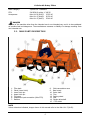
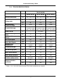
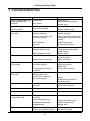
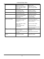
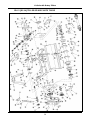
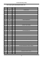
1
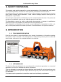
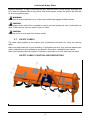
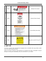
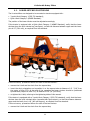
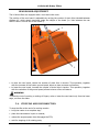
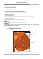
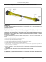
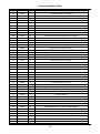
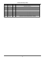
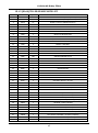
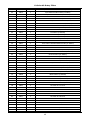
ROTARY TILLERS UL - SERIES UL0.9 (UL36) – UL1.2 (UL48) – UL1.5(UL60) OPERATOR'S & PART’S MANUAL Tirth Agro Technology Pvt. Ltd. ISO 9001:2008 Certified Company Manual P/N: OM 1121-1 / REV. 06 / 2015 PM 1121-1 / REV. 05 / 2015 Congratulation for purchasing your new SUNDOWN rotary tiller! This tiller has been designed and manufactured following all safety and quality requirements needed for a safe and satisfactory use over time. A careful reading of this manual will permit you to familiarize with your new equipment, and will provide you all the tools needed to use it safely. A proper maintenance and knowledge of the safety rules of use will allow to obtain the best performance and a long service life of the machine. The Safety Alert Symbol used throughout this manual and on safety decals of the machine indicates the presence of potential hazard to the operator. When you see this symbol, be alert and carefully read the message that follows it. The Safety Alert Symbol is used in conjunction with following Signal Words, according to the degree of possible injuries that may result operating the implement: DANGER Indicates an imminently hazardous situation that, if not avoided, will result in death or serious injury. WARNING Indicates a potentially hazardous situation that, if not avoided, could result in death or serious injury, and includes hazards that are exposed when guards are removed. It may also be used to alert against unsafe practices. CAUTION Indicates a potentially hazardous situation that, if not avoided, may result in minor or moderate injury. It may also be used to alert against unsafe practices. IMPORTANT Indicates instructions or procedures that, if not observed, can cause damage to equipment or environment. NOTE Indicates helpful information. READ, UNDERSTAND, and FOLLOW the safety messages following the Safety Alert Symbol and Signal Words. Failure to comply with safety messages could result in serious bodily injury or death. TO THE PURCHASER This manual contains valuable information about SUNDOWN ROTARY TILLER. It has been carefully prepared to give you helpful suggestions for operating, adjusting, servicing repair parts. Keep this manual in a convenient place for quick and easy reference. Study it carefully. You have purchased a dependable and sturdy tiller, but only by proper care and operation can you expect to get the service and long life designed and built into it. RIGHT-HAND AND LEFT-HAND sides are determined by watching from the tractor side. Sometime in the future your tiller may need new parts to replace those are worn or broken. If so, go to nearest SUNDOWN dealer and provide him the model and part number. Customer information Name Purchased from Purchased date Model No. Serial No. TABLE OF CONTENTS 1. ABOUT THIS MANUAL................................................................... 1 2. INTRODUCTION............................................................................... 1 2.1. 2.2. TILLER IDENTIFICATION................................................................................................................ INTENDED USE.................................................................................................................................... MAIN PARTS DESCRIPTION.......................................................................................................... TILLER SPECIFICATION................................................................................................................... 1 1 3. SAFETY............................................................................................... 4 3.1. 3.2. 3.3. 3.4. 3.5. 3.6. 3.7. GENERAL SAFETY INSTRUCTIONS............................................................................................. EQUIPMENT SAFETY INSTRUCTIONS....................................................................................... OPERATING SAFETY INSTRUCTIONS........................................................................................ TRANSPORTING SAFETY INSTRUCTIONS............................................................................... MAINTENANCE SAFETY INSTRUCTIONS................................................................................. STORAGE SAFETY INSTRUCTIONS.............................................................................................. SAFETY LABELS.................................................................................................................................. SAFETY LABELS POSITION AND DESCRIPTION........................................................... 4 5 6 7 8 8 9 9 4. SET-UP................................................................................................ 10 4.1. 4.2. 4.3. 4.4. LOWER HITCHES POSITIONING.................................................................................................. CONNECTING TO THE TRACTOR................................................................................................. DRIVELINE INSTALLATION........................................................................................................... DRIVELINE LENGTH CHECK................................................................................................. TRACTOR-TILLER STABILITY....................................................................................................... 5. OPERATING....................................................................................... 14 5.1. 5.2. 5.3. 5.4. 5.5. START UP................................................................................................................................................ OPERATING INSTRUCTIONS.......................................................................................................... ADJUSTMENTS..................................................................................................................................... LOWER CLEVISES ADJUSTMENT......................................................................................... FRICTION CLUTCH ADJUSTMENT....................................................................................... SKIDS ADJUSTMENT................................................................................................................. REAR BOARD ADJUSTMENT.................................................................................................. STOPPING AND DISCONNECTION............................................................................................... TRASPORTING...................................................................................................................................... 6. MAINTENANCE................................................................................. 21 6.1. BLADES REPLACEMENT.................................................................................................................. 2.3. 2.4. 2 3 11 12 12 12 14 14 15 16 16 17 18 19 19 20 21 6.2. 6.3. 6.4. 6.5. GEARBOX LUBRICATION................................................................................................................. SIDE CASE LUBRICATION................................................................................................................ BEARING HOUSING LUBRICATION............................................................................................. DRIVESHAFT MAINTENANCE....................................................................................................... 7. STORAGE........................................................................................... 26 8. SCRAPPING....................................................................................... 26 9. TROUBLESHOOTING...................................................................... 27 22 23 24 24 10. TORQUE VALUES TABLE.............................................................. 29 11. WARRANTY…………………............................................................... 30 12. SPARE PARTS................................................................................... 33 U-Series UL Rotary Tillers 1. ABOUT THIS MANUAL The operator must read the manual for a correct understanding of the hazards that may present when operating the tiller, as well as for obtain optimum performance from the machine. The manual is part of the machine, it must be kept in good condition and remain with the machine even in case of resale, until its demolition. In case of loss or damage, request a new copy to the Manufacturer or your Dealer. The information, descriptions and illustrations in this manual describes the state of the product at the time of its publication, and may not reflect the product in the future. The Manufacturer reserve the right to make design improvements or changes in specifications without incurring in any obligation to install them on units previously sold. Text, illustrations and drawings of this manual cannot be disclosed or transmitted, in whole or in part, to third parties without the written permission of the Manufacturer. All rights are reserved. 2. INTRODUCTION 2.1. TILLER IDENTIFICATION Each tiller has a plate for unique identification. Any request for assistance or information regarding the machine must be directed to the Manufacturer or Dealer always referring to the model and serial number as shown on the nameplate affixed to the machine: 2.2. INTENDED USE The U-series tillers are designed to be used uniquely for horticultural, agricultural, or commercial applications, to till soil for seedbed and planting preparation. They are designed to be mounted on tractors equipped with hydraulic lift and universal three point hitch that can support the implement weight, and driven by the power of the tractor through the PTO driveshaft. The tractors used to operate the U-series tillers must have the following requirements: 1 U-Series UL Rotary Tillers Hitch Category: PTO: Horsepower: 3-point Cat. I standard 540 RPM, 6-spline, 1 3/8 Z6 tiller UL0.9 (UL36): 15-25 HP tiller UL1.2 (UL48): 20-30 HP tiller UL1.5 (UL60): 25-40 HP DANGER Any use of the machine other than the intended use is non-intended use, and is to be considered as unauthorized and dangerous. The manufacturer assumes no liability for damage resulting from non-intended use. 2.3. MAIN PARTS DESCRIPTION 1. 2. 3. 4. 5. 6. 7. Tiller deck Clevis (lower hitch) Lower hitch pin Upper hitch pin Top mast Implement input connection (tiller PTO) Gearbox 8. 9. 10. 11. 12. 13. 14. 15. Side transmission case Rear board Rotor shaft Tine Parking stand Skid Cardan driveshaft PTO shield NOTE Unless otherwise indicated, images shown in this manual refer to the tiller UL1.5 (UL60). 2 U-Series UL Rotary Tillers 2.4. TILLER SPECIFICATIONS TILLER MODEL UL0.9 (UL36) UL1.2 (UL48) UL1.5 (UL60) mm 1035 x 805 x 600 1340 x 805 x 600 1645 x 805 x 600 in 36'' 48'' 60'' cm 92 122 153 HP 15-25 20-35 25-40 3-point Hitch type - Cat. I, Compatible Quick Hitch I cat. ASAE Cat. I, Compatible Quick Hitch I cat. ASAE Cat. I, Compatible Quick Hitch I cat. ASAE Frame off-set in - 4'' or NIL* - No. 4 6 7 No. 24 36 42 rpm 540 540 540 rpm @540 245 242 242 Standard Tine Construction - curved curved curved Transmission type - gear gear gear Max Working depth cm 16 16 16 Rotor tube diameter mm 70 70 70 Rotor Swing Diameter mm 375 375 375 Driveline safety device - slip clutch slip clutch slip clutch lbs 337 397 441 Kg. 153 181 200 Overall dimensions Tilling width Recommended Tractor HP range Number of Flanges on Rotor Number of tines per Flange PTO Input speed Rotor Shaft Speed Weight (driveline excluded) * Note: - UL 1.2 (UL 48) Centre Mounted Tiller Model available as per request. 3 U-Series UL Rotary Tillers 3. SAFETY Proper use of equipment, a strict observance of the safety messages listed below and application of all reasonable practices to avoid any risks, prevents accidents or injury, allows the machine working better and longer, and minimize the failures. The manufacturer assumes no liability for any damage resulting from not applying the behavioral rules indicated into the manual. 3.1. GENERAL SAFETY INSTRUCTION DANGER The machine must be used only by authorized and well trained operators. The operator must have read and understood the instructions of this manual, it must make adequate preparation for the proper use of the machine and must hold a driving license. In case of doubt about the use of the machine and/or the interpretation of this manual, the operator must contact the Manufacturer or the Dealer. WARNING The manual must always remain with the machine. In case of loss or damage, request a new copy to the Manufacturer or your Dealer. WARNING Follow strictly the rules prescribed by the safety pictograms applied to the machine. WARNING Be sure that all safety pictograms are legible. If pictograms are worn, they must be replaced with others obtained from the Manufacturer, and placed in the position indicated by this manual. DANGER Before using the machine, make sure that all safety devices are installed and in good working conditions. In case of damages of shields, replace them immediately. DANGER Is absolutely forbidden to remove or alter safety devices. DANGER Before starting, and during operation of the tiller, make sure there are no people or animals in the operation area: the machine can project material from the back, with risks of serious injury or death. DANGER Pay maximum attention to avoid any accidental contact with rotating parts of the machine. DANGER During operation, adjustment, maintenance, repairing or transportation of the machine, the operator must always use appropriate Personal Protective Equipment (PPE). DANGER Do not operate the implement while wearing loose fitting clothing that can give rise to entanglement in parts of the machine. 4 U-Series UL Rotary Tillers DANGER Do not operate the implement when tired, not in good condition or under the influence of alcohol or drugs. CAUTION If the use of the machine is required at night or in conditions of reduced visibility, use the lighting system of the tractor and possibly an auxiliary lighting system. 3.2. EQUIPMENT SAFETY INSTRUCTIONS WARNING Use the tiller for its intended purpose only. Improper use can damage the tiller and cause serious injury to persons, animals, or death. DANGER The machine should be used by a single operator driving the tractor. WARNING Any unauthorized modification of the machine may cause problems in safety and relieves the Manufacturer from any liability for damages or injuries that may result to operators, third parties and objects. WARNING Before using the machine, familiarize yourself with its controls and its working capacity. WARNING Do not leave the tiller unattended with tractor engine running. WARNING Do not operate tiller on too muddy, sandy or rocky soils. WARNING Keep the machine clean from debris and foreign objects which may damage functioning or cause injury. WARNING Do not use the machine if the category of the connecting pins of the tiller does not match that of the tractor hitch system. WARNING Do not use the machine with missing bolts, screws, pins or safety pins. WARNING Never use the machine to transport or lift people, animals or objects. WARNING Make certain, by adding front ballast, that at least 20% of the total weight (tractor, implement and ballast) is on the front axle of the tractor, to ensure stability. 5 U-Series UL Rotary Tillers WARNING Before engaging the tractor PTO, make sure the tractor PTO speed is set as required for the tiller (540 rpm). Do not over speed PTO or machine breakage may result. DANGER Do not operate the tiller if the driveshaft is damaged. The driveshaft could be subject to breakage during operation, causing serious injury or death. Remove the driveshaft and replace it with an undamaged. 3.3. OPERATING SAFETY INSTRUCTIONS WARNING Before using the machine, be sure to have cleared the operating area from obstacles (stones, branches, debris, etc...). Mark all the obstacles that cannot be eliminated (e.g. by means flags). DANGER Never engage the tractor PTO in the presence of people close to the driveshaft. The body, hair or clothing of a person can get caught in rotating parts, causing serious injury or death. DANGER Before engaging the PTO and during all operations, make sure that no person or animal is in immediate area of action of the machine. Never use the tiller if people are in his working area. DANGER It's absolutely forbidden to stand near the tiller with moving parts. WARNING The operator must operate tiller lifting/lowering only from the driving seat of the tractor. Do not perform lifting maneuvers on side or behind the tractor. WARNING Before making changes in direction, turns or going in reverse, slightly lift the tiller from the ground after disengaging the power take-off, to avoid damage to the machine. DANGER In presence of steep slopes (greater than 15 degrees) the tilling action may cause instability of the tractor, with risk of tipping and consequent serious injury or death hazard. Consult the manual for the tractor to determine the maximum slope that the tractor is able to deal with. DANGER Always disengage the PTO before raising the tiller, and never engage the PTO with the tiller in the raised position. The machine might throw objects at high speed, causing serious injury or death. WARNING Never leave the driver's seat when the tractor is turned on. Before leaving the tractor, lower the tiller to the ground, disengage the PTO, insert the parking brake, stop engine and remove the key from the control panel. DANGER 6 U-Series UL Rotary Tillers The PTO shields of tractor and implement side, the driveshaft shielding and the driveshaft retaining chains must be properly installed and in good condition, to avoid risk of entanglement with serious injury or death. DANGER Before engaging the PTO of the tractor, always make sure that the drive shaft is mounted in the correct direction, and that its clamping elements are properly connected both to tractor side and to tiller side. WARNING Stop operating immediately if blades strike a foreign object. Repair all damage and make certain rotor and blades are in good condition before resuming operation. WARNING Always disengage the tractor PTO when the driveshaft exceed an angle of 10 degrees up or down while operating. An excessive angle with driveshaft rotating can break the driveshaft and cause flying projectiles. CAUTION Avoid clutch's overheating caused by too long or frequent slipping of the clutch, since it can damage the clutch components. Before checking slip clutch, make sure it has cooled. Clutch could be extremely hot and cause severe burn. CAUTION Prolonged use of the tiller can cause overheating of the gearbox. Do not touch the gearbox during use and immediately after, it could be extremely hot and cause severe burn. WARNING All adjustment operations on the tiller must be performed by qualified and trained operators, with the tractor engine off, the PTO disengaged, the tiller lowered to the ground or on security stands, the ignition key off and the parking brake set. 3.4. TRANSPORTING SAFETY INSTRUCTIONS WARNING Before transporting, determine the stopping characteristics of the tractor and implement. WARNING Transport only at speeds where you can maintain control of the equipment. WARNING When driving on roads, the implement must be in transport position adequately raised from the road surface, with tractor lifting hydraulics locked so that the tiller cannot be lowered accidentally. DANGER The implement may be wider than the tractor. Pay attention during transporting to persons, animals or obstacles exposed. 7 U-Series UL Rotary Tillers WARNING When turning, use extreme care and reduce tractor speed. WARNING Do not operate the tractor with weak or faulty brakes or worn tires. CAUTION Always use tractor lighting system and auxiliary lighting system for an adequate warning to operators of other vehicles, especially when transporting at night or in conditions of reduced visibility. DANGER In case of tiller lifting, make sure that the lifting device chosen is suitable to perform the operation safely, and use only the lifting points prescribed on tiller. 3.5. MAINTENANCE SAFETY INSTRUCTIONS WARNING All maintenance and repairing operations must be performed by qualified and trained operators, with the tractor engine off, the PTO disengaged, the tiller lowered to the ground or on security stands, the ignition key off and the parking brake set. WARNING Perform repairs and replacements necessary to parts provided by the manufacturer or your dealer. the machine using only original spare DANGER Perform maintenance operations always using appropriate Personal Protective Equipment (protective eye glasses, hard hat, hearing protection, safety shoes, overall and work gloves, filter mask). CAUTION Before any maintenance operation, make sure that the parts which may become hot during use (friction clutch, gear box...) have cooled. WARN4435G Do not perform repairs that you do not know. Always follow the manual instructions and in case of doubt contact the Manufacturer or your dealer. DANGER Do not swallow fuels or lubricants. In case of accidental contact with eyes, rinse well with water and consult a doctor. 3.6. STORAGE SAFETY INSTRUCTIONS WARNING Never leave the tractor unattended with the tiller in lifted position. Accidental operation of lifting lever or a hydraulic failure may cause sudden drop of unit with injury or death by crushing. DANGER 8 U-Series UL Rotary Tillers Following operation, or before unhooking the tiller, stop the tractor, set the brakes, disengage the PTO, lower the attached tiller to the ground, shut off the engine, remove the ignition key and wait for all moving parts to stop. WARNING Make sure all parked machines are on a hard, level surface and engage all safety devices. CAUTION Place support blocks under tiller as needed to prevent unit from tipping over onto a child and/or an adult. A tiller that tips over can result in injury or death. CAUTION Store the unit in an area away from human activity. 3.7. SAFETY LABELS The safety labels applied on the machine give fundamental information for using the machine safely. Make sure safety labels are in good conditions. If pictograms are worn, they must be replaced with others obtained from the manufacturer and placed in the position indicated by this manual. Make sure the safety labels are legible. If necessary, wipe them by a cloth, with soap and water. SAFETY LABELS POSITION AND DESCRIPTION 9 U-Series UL Rotary Tillers 1 D1103 Rotating Tines Hazard. 2 D1105 Rotating Driveline Hazard. 3 D1106 General Safety Instructions. 4 D1107 Operate only with 540 rpm PTO. 4. SET UP The tiller is delivered fully assembled and equipped with a driveshaft with torque limiter (clutch discs) and related operating manual. When the machine is delivered, check that there is no damage to the tiller or driveshaft. In case of damage or missing parts immediately notify the manufacturer or your dealer. 10 U-Series UL Rotary Tillers 4.1. LOWER HITCHES POSITIONING The U-series tillers are designed to be mounted on tractors equipped with: 3-point Hitch Category I (ISO 730 standard); Quick Hitch Category I (ASABE Standard). The position of the lower hitches must be adjusted accordingly. If the tractor is equipped with a Quick Hitch Category I (ASABE Standard), verify that the lower clevises show the pins oriented up (see figure), so that the distance between upper and the lower pins is 15'' (381 mm), as required from the standard. If this not occurs, proceed as follows for each of the two clevises:: remove the U-bolt and the clevis from the square tube; invert the clevis orientation and reposition it on the square tube at distance of 13 7/16'' from the center of tiller PTO. At the end of the operation the lower clevises should be positioned symmetrically respect to tiller PTO, at distance of 26 7/8'' (683 mm); re-tighten the U-bolt, referring to the tightening table of this manual. If the tractor is equipped with a 3-point Hitch Category I (ISO 730 standard), verify that the lower clevises show the pins oriented down (opposite than figure above), so that the distance between upper and the lower pins is 18'' (460 mm approx), as required from the standard. If this not occurs, proceed as follows for each of the two clevises: remove the U-bolt and the clevis from the square tube; 11 U-Series UL Rotary Tillers invert the clevis orientation and reposition it on the square tube at distance of 13 7/16'' from the center of tiller PTO. At the end of the operation the lower clevises should be positioned symmetrically respect to tiller PTO, at distance of 26 7/8'' (683 mm); re-tighten the U-bolt, referring to the tightening table of this manual; remove from upper and lower pins the bushings provided for coupling with Quick Hitch, through the extraction of elastic pins. Replace the elastic pins when finished. Store the bushings for possible future use. 4.2. CONNECTING TO THE TRACTOR To connect the tiller to the tractor the operator must do the following: drive the tractor in reverse, up to align the rear lifting arms to lower hitches of the tiller in parking; set the tractor's parking brake, stop engine, remove the ignition key and get off the tractor; connect the lifting arms of the tractor to the lower hitches of the tiller, through the use of the pins and the relative safety split pins; raise the tiller until PTOs of tractor and machine are at the same height, then adjust the 3-point top link so that the front of the machine is leveled to the back (the axis of the tiller PTO must be parallel to the ground), in order to limit stress transmitted to the tiller through the cardan shaft; make sure that left side of the tiller is leveled with the right, by adjusting the tractor lifting arms, then lock the arms to prevent swinging that could compromise the stability of tractor and machine; finally adjust the parking stand, placing it at the highest point by means of the related elastic pin. 4.3. DRIVELINE INSTALLATION Before installing the driveshaft, the operator must read the manuals of driveshaft and tractor, checking in particular that rpm and direction of rotation of the tractor PTO match those of the tiller. If the direction of rotation of the PTO tractor does not match that of the tiller, contact the manufacturer or your dealer. To connect the driveshaft to the tractor and implement, the operator must: park tractor and tiller on a flat surface, with parking brake set, engine off, and ignition key removed; check that safety devices of driveshaft, tiller and tractor are in good condition, otherwise provide for their replacement; remove the PTO shield of the tiller through the fixing screws; position the driveshaft with clutch turned towards the implement side; insert the clutch hub on the tiller PTO, then ensure its tightening onto shaft through its fastener; replace the PTO shield of the tiller through the fixing screws; insert the driveshaft yoke on the tractor PTO, then ensure its tightening onto shaft through its fastener; 12 U-Series UL Rotary Tillers hook to the tractor and tiller the two retaining chains of the the driveline shielding, to prevent shielding rotation during functioning of the machine. DRIVELINE LENGTH CHECK Before operating the tiller, ensure that the size of driveshaft is adequate. The driveshaft supplied with the machine has a standard length, therefore it may need an adaptation of the length, depending of the tractor which the tiller is combined. The length of the driveshaft must be such to: avoid bottom out of the transmission tubes, when the driveshaft is in compressed position (when tiller is raised up off the ground); ensure an overlapping of the transmission tubes enough to transmit the torque required, when the driveshaft is in max extension (when tiller is in its lowest position in the ground). When the driveshaft is at its minimum length (max compressed position), there must be at least a 2 cm of distance between the ends of each transmission tube and the yokes side. When the driveshaft is at its maximum operational extension, there must be an overlap between the tubes profiles of 15 cm at least. A driveshaft too long may cause structural damages to the tractor and machine. If the driveshaft is too long, it may be adapted by removing it and shortening the tubes according to the instructions provided by the manufacturer in its use and maintenance manual. A driveshaft too short can cause disengage of the tubes during operation, with severe hazard for the operator and structural damage to the tractor and machine. If the driveshaft is too short, it must be replaced with a longer one. In this case contact the manufacturer or your dealer. 13 U-Series UL Rotary Tillers IMPORTANT before operating the tiller the first time, make sure that the driveshaft is lubricated in accordance with how indicated in the instruction booklet; before operating the tiller the first time, and after long periods of inactivity, make sure that the driveline clutch has run a short "run in" in accordance with what indicated in the instruction manual of the manufacturer, removing the possible oxidation of the components that may compromise the correct slipping during the usage (see also section "Maintenance"); always engage the tractor PTO at low rpm to minimize the effect of the peak torque on the driveline and the machine. 4.4. TRACTOR-TILLER STABILITY The weight of the machine modifies the stability of the system tractor-tiller, resulting in loss of steering control and braking. The front axle of the tractor should always loaded with at least 20% of the overall weight of the system tractor-tiller. CAUTION Check the lifting capacity and stability of the tractor and, if necessary, applying the front ballast. To determine the appropriate characteristics of the ballast, refer to the manual of the tractor. 5. OPERATING Before operate the tiller, make sure you have read and understood the operating manuals of the tiller, tractor and PTO shaft, and followed what is described in the section "Set Up". DANGER During operation, adjustment, maintenance, repairing or transportation of the machine, the operator must always use appropriate Personal Protective Equipment (PPE). Before starting work, ensure that all machine guards are in good conditions and fully functional. During operation, the machine can throw material from the back: prevent people and animals to approach the operational area. 5.1. START UP Before the start up and before each use, perform the following pre-operation inspections and service of the implement: check that the tiller has not damaged functional parts and has all mechanical parts in good condition. Repair and / or replace the damaged parts; check that the tiller has no missing parts (pins, safety pins, plugs oil ...). Restore the missing parts; check that all guards and safety devices have no damages and are properly positioned. Repair and / or replace the damaged shieldings, restore the correct position; verify that the PTO driveshaft is properly installed (see section: Connection of the drive shaft); 14 U-Series UL Rotary Tillers check that the driveshaft clutch is in good condition, and that its components are not subject to "sticking" (see section: Maintenance / Driveline); check the presence of lubricant in all greasing points of the tiller (driveshaft, supports...) (see sect. Maintenance / Driveline and Maintenance / Support rotor); check for oil leaks from the gearbox or the transmission side cover. Identify the reason of loss, then repair and / or replace the damaged components; check the correct oil level in the gearbox and in transmission side box (see section maintenance); check that blades are not excessively worn and the relating hardware is correctly tightened (see sect. Maintenance); check that all the tiller hardware is properly tightened. Refer to the tightening table in the manual for proper torque values; check that all safety dacals are correctly positioned, in good condition and legible. Replace any damaged decals; check that there is no constraints that may prevent the movement of equipment. Remove any constraint. Before the start up and before each use, make the following checks on the operating area identified for tillage: check that area is clear of foreign objects (rocks, branches or debris). Remove any obstacle and visibly highlight obstacles that cannot be eliminated (e.g. by means flags); make sure in the working area exposed there are no people or animals; make sure the soil to be worked is not too grassy, muddy, sandy or rocky. WARNING Before conducting the above inspections and service, make sure the tractor engine is off, all rotation parts are completely stopped and the tractor is in park with the parking brake engaged. Make sure the tiller is resting on the ground or securely blocked up and the tractor lifting hydraulics locked. Once all the checks above have been done, start tractor and the tiller as follows: start the tractor and engage the tractor PTO at low rpm, making sure that the tiller is NOT in the raised position but close to the ground, then increase speed engine until to 540 rpm; lower the tiller on the ground and simultaneously start driving the tractor at low speed. Subsequently increase the ground speed depending on ground conditions; If the environmental temperature is very cold , it's recommended to wait a few minutes with the PTO of the tractor at low rate before lowering the tiller completely on the ground; drive for a while operating the tiller, then stop the tractor to check the quality of the work performed. If you need to get off the tractor, lift the tiller just out of the ground, reduce engine speed and disengage PTO, set the parking brake, stop engine and remove the ignition key; If the working depth and/or soil texture are not as desired, correct them by adjusting the skids and/or the rear cover (see section Adjustments). 5.2. OPERATING INSTRUCTIONS During operations:/ OPERATE ACCORDING TO FOLLOWING INTRUCTION 15 U-Series UL Rotary Tillers always keep the tractor engine at rpm rate ensuring to the tiller the right power required for the use; always keep a tractor speed adequate to conditions of the soil to be worked (from 2 to 10 km / h approx.). Reduce speed in the case of hard or stony soils; choose a driving pattern that provides the maximum pass length and minimizes turning; when working in the hills, if you can do "climbing" in the sense of the slope, in any case do not work along the hillsides, making the steps from top to bottom to reduce the terrace Where possible always try to «work up» the slope. If this is not possible avoid hoeing along the contours of the hill and hoe up and down the slope to avoid a terracing effect; always perform changes and reverse of direction with PTO disengaged and the tiller slightly lifted from the ground to avoid damage to the machine; periodically check for foreign objects wrapped around the rotor shaft and remove them, after disengaging PTO, turning off tractor engine, and removing ignition key; if the blades strike a foreign object, or in case of prolonged intervention of the clutch due to an object wedged into the rotor, stop operating immediately, idle the engine speed and disengage the PTO. Wait for stopping of all rotating parts, then raise the implement and proceed to removing the object, after stopped the tractor, set the parking brake, stopped engine and removed the ignition key. Repair any damages immediately, and make sure rotor and blades are in good condition before restarting operation; avoid friction clutch overheating caused by too long or too frequent slipping of the clutch, since this can damage the friction plates and clutch parts. Typical problems that may occur operating the tiller are described into Troubleshooting section, together with their solutions. 5.3. ADJUSTMENTS WARNING All adjustment operations must be performed with the tractor engine off, the PTO disengaged, the tiller lowered to the ground or on security stands, the parking brake set and the ignition key off. LOWER CLEVISES ADJUSTMENT It is possible to adjust the lower hitch position loosening the bolts 1 (see picture) and sliding the clevis 2. Tighten the bolts after making any adjustment required. 16 U-Series UL Rotary Tillers 2 1 1 FRICTION CLUTCH ADJUSTMENT The PTO driveshaft and friction clutch are designed to transmit adequate power to the tiller. The clutch preserves the machine from overloads, through the slipping of friction discs, and limits the max torque transmissible to a calibrated value set at factory. It is recommended, therefore, to leave unchanged this value to avoid damages to the machine or to driveshaft. An adjustment can be done, however, when the clutch slipping is too frequent, which means that the calibration is too low. In this case, the tightening of nuts over the compressed springs will give an increase in torque transmissible. On the contrary, a loosening of the nuts over the springs will give a decrease in torque transmissible. IMPORTANT 17 U-Series UL Rotary Tillers For details about clutch adjustment, refer to the user manual of the manufacturer of the driveshaft installed. The manufacturer is not liable for damages resulting from a wrong modification of the clutch calibration. NOTE Excessive tightening of the springs can prevent the clutch from slipping and to protect the machine from overload. Make sure that the height of all the compressed springs is equal to prevent clutch malfunctioning. SKIDS ADJUSTMENT The working depth of the tiller is determined by the position of the side skids: it may be increased by raising the skids, and decreased by lowered them. It's important that both skids are adjusted at the same height. To adjust the working depth, perform the following steps: lift the machine, put it safely on security stands, then switch the tractor engine off, disengage PTO, set parking brake and off the ignition key; loosen the in the front of the skid (bolt 1 - see picture); unscrew and remove the bolt on the rear of the skid (bolt 2 - see picture); adjust the height of the skid through the holes, as desired; reinstall the bolt 2 (refer to the tightening table of this manual for proper torque values); tighten the bolt 1 (refer to the tightening table of this manual for proper torque value). 1 1 2 2 When finished, verify that both skids are at same level, and check if the front of the tiller is leveled to the back, when lowered to the ground. Adjust with the 3-point top link if necessary. 18 U-Series UL Rotary Tillers REAR BOARD ADJUSTMENT The U-Series tillers are equipped with a rear board with chain. The position of the rear board is adjustable by varying the number of chain links included between distance XY, which remain tensioned under the weight of the board (i.e. links between the rear board U-bolt 1 and the slot of the frame 2). 2 1 to raise the rear board, reduce the number of chain links in tension. This operation, together with the increase of the tractor ground speed, allows to have a coarser soil texture; to lower the rear board, increase the number of chain links in tension. This operation, together with the reduction of the ground speed, allows to have a finer soil texture. WARNING To avoid the risk of crushing or cutting of fingers, raise or lower the rear board only from the lower edge, not from the sides. 5.4. STOPPING AND DISCONNECTION To stop the tiller at the end of a working session: bring the tractor to a complete stop; place the transmission in park or neutral; reduce the engine speed, then disengage the PTO; wait for stopping of all rotating parts; 19 U-Series UL Rotary Tillers lower the implement to the ground; set the parking brake; shut down the engine and remove the key before exiting the tractor; do the cleaning and maintenance required to make the machine ready for later use (see Section Maintenance). WARNING Never leave the tractor unattended with the implement in the lifted position. To disconnect the tiller from the tractor (e.g. to make a change of implement): adjust the skids to their lowest position (see Section Adjustments); adjust the parking stand to the lowest position, through the use of relative retaining pin; park the tractor on a dry and level surface; reduce the engine speed, then disengage PTO; wait for stopping of all rotating parts; lower the implement to the ground; set the parking brake; shut down the engine and remove the key before exiting the tractor; place safety blocks under tiller to prevent unit from tipping over onto a child and/or an adult. A tiller that tips over can result in injury or death; disconnect the driveline from the tractor PTO and rest it on the provided support of the tiller; disconnect the top link and rear lifting arms of the tractor from the tiller hitches; check the tiller stability. If needed, place additional safety blocks; get on the tractor, start the engine and move away from the tiller slowly; make sure the tiller remains stored in a protected area, to prevent that unauthorized personnel can approach it. Before a long term storage (e.g. at seasonal end), do cleaning and maintenance operations as specified in Sections MAINTENANCE and STORAGE. 5.5. TRASPORTING To set the tiller for transportation, perform the following steps: idle tractor engine, disengage tractor PTO, and wait for stopping of all rotating parts; lift the tiller until the transport position, making sure the driveline transmission tubes does not contact tractor or tiller. A minimum gap of 2 cm should be leaved between the tubes and tractor and tiller (see also Section Driveline installation); lock the tractor lifting hydraulics, turn off the engine, set the parking brake, remove ignition key and get off the tractor; adjust the parking stand to the highest position, through the use of relative retaining pin, to prevent its possible damage during transport. When driving on public roads, follow strictly all local laws and traffic regulations. WARNING 20 U-Series UL Rotary Tillers When driving on public roads, reduce your speed, be aware of traffic around you and proceed in such a way that faster moving vehicles may pass you safely. 6. MAINTENANCE Proper and regular maintenance ensures a long life of the equipment, avoids failures and saves time and repair costs. Periodic inspections and maintenance operations described in this section must be performed by operator in the times and terms prescribed. Failure to comply with maintenance prescriptions can compromise the functioning and duration of the machine, and consequently invalidate the warranty. The frequency of maintenance indicated refers to normal conditions of use: it must be intensified in severe operating conditions (frequent stops and starts, prolonged winter season etc ...). Repairs, maintenance and modifications other than those mentioned in this paragraph should NOT be performed without consulting the manufacturer or your dealer. Manufacturer, as the case, may give the authorization to proceed with the repair together with all necessary instructions. Wrong or inappropriate repairs or maintenance may generate abnormal operating conditions, equipment damage and generate risks for the operator. WARNING For safety reasons, all maintenance operations must be performed with tractor PTO disengaged, tiller stopped and completely lowered to the ground or onto support blocks, parking brake set, tractor engine shut off, and ignition key removed. IMPORTANT Respect the environment. Store or dispose of unused chemicals as specified by the chemical manufacturer. 6.1. BLADES REPLACEMENT Frequently check the wear condition of blades through visual inspection. The wear of blades is very variable depending on the type of soil. Replacement of the blades is necessary when the operator notices increase of power absorption during tilling, or when the blade dimension is significantly reduced compared to the original. The use of the machine with blades in bad condition compromises the quality of work. Before perform replacement of the blades: idle tractor engine, set the parking brake, disengage tractor PTO, and wait for all moving parts to come to a complete stop; place the tiller slightly lifted from the ground on safety blocks or mechanical stands; lock the control lever of the hydraulic lift of the tractor; turn off the tractor and remove the key. To perform the replacement of blades: remove the two bolts and washers clamping the blade to the rotor flange, then remove the blade; position the new blade exactly instead of the worn blade, then tighten the bolts, referring to the tightening table of this manual for proper torque values. Be sure to install the blade with cutting edge in front of the direction of rotation; 21 U-Series UL Rotary Tillers repeat the same procedure for all the other blades. At the end of the replacement, make sure the blades have the right helical arrangement, as shown in the figure: Periodically check the tightness of screws and nuts, and tighten if necessary. IMPORTANT Remove and install one blade at a time to ensure blades are correctly oriented when installed. Replace worn blades only with original parts. CAUTION Worn tines may be very sharp! 6.2. GEARBOX LUBRICATION Lubricant: SAE EP 80W90 gear oil Check the oil level every 50 hours, making sure the oil mark left on the dipstick of the filling plug (top of gearbox) is located between the two reference marks (minimum and maximum). Filling Plug drain Plug 22 U-Series UL Rotary Tillers If the sign is below the minimum, fill up oil till restore the correct level. The oil change must be performed: after the first 50 working hours; each 500 working hours. To make the oil change: place a tank under the oil drain plug (bottom of gearbox) ; unscrew the oil drain plug and drain oil completely into the tank; retighten the drain plug; unscrew the oil filling plug; fill up oil till restoring the correct level (between the two reference dipstick marks) ; retighten the filling plug; dispose the discharged oil into containers for used oil. CAUTION Before touching the gearbox wait until it has cooled sufficiently. IMPORTANT Frequently check possible oil leaks from tiller through visual inspection, and in case of leakage provide immediately proper maintenance. Avoid oil leaks on the ground when restoring oil level or making oil change. 6.3. SIDE CASE LUBRICATION Lubricant: SAE EP 80W90 gear oil Filling Plug Transmission cover Level plug Check the oil level every 50 hours, making sure it reach’s the level plug on the transmission cover. 23 U-Series UL Rotary Tillers If the oil is below this level, fill up oil till restore the level. The oil change must be performed every 500 working hours. To make the oil change: remove the skid from the transmission side; place a tank under the oil level plug; unscrew the oil level plug and drain completely the oil into the tank; retighten the level plug; unscrew the oil filling plug (top of transmission cover); fill up oil till restoring the correct level (until level plug); retighten the filling plug; replace the side skid; dispose the discharged oil into containers for used oil. 6.4. BEARING HOUSING LUBRICATION Lubricant: SAE multi-purpose lithium-type grease Grease the rotor hub support every 8 working, through a suitable grease gun. Grease zerk IMPORTANT Make sure to clean the fitting zerk before using grease gun. Do not let excess grease collect on or around parts, particularly when operating in sandy areas. 6.5. DRIVESHAFT MAINTENANCE Lubricant: SAE multi-purpose lithium-type grease 24 U-Series UL Rotary Tillers Grease crosses, sliding parts of protective shielding and driveshaft transmission tubes. IMPORTANT For details about maintenance and lubrication of the driveshaft, refer to the user manual of the driveshaft manufacturer. Driveshaft clutch: Exposition to the elements of tiller and driveshaft, or a long period of inactivity, generally results in oxidation of some clutch components, and creates "sticking" effect on the clutch. Consequently, the torque required to the slippage of the clutch increases considerable respect to the value set at factory, and this may be cause of driveshaft breakage during operation, or damage to the tractor or implement. To avoid it, before re-using the tiller, operator must perform a short "run-in" of the clutch, as follows: take note of the height of the compressed springs; loosen the bolts that compress the springs; connect the tiller to the tractor (see section Conneting to the tractor) ; connect the driveshaft (see section Driveline installation) ; start the tractor and engage PTO for few seconds, in order to cause slippage and separation of the parts "sticked" of the clutch; turn off the tractor, remove key and wait for all components are stopped before dismounting from tractor; retighten the bolts restoring the original springs position on the driveshaft. NOTE For replacement of the driveshaft service parts (e.g. friction discs), refer to the user manual of the driveshaft manufacturer. 25 U-Series UL Rotary Tillers 7. STORAGE Before leaving the tiller unused for a long time, it's necessary to perform following tasks to preserve the appearance and functionality of the machine, and to make easier the restart at later use: park the tiller on a flat surface, in a place dry and protected from exposition to the elements, possibly with storage temperature between 0 and 50 ° C (see Section Stopping and disconnection); thoroughly clean the machine, removing from the rotor all residues due to tillage, in order to avoid damage from grass and stagnant water; inspect carefully the machine, checking for worn and/or damaged parts. Perform immediately all repairs and/or replacements needed, in order to make the machine ready for restarting; in case of abrasion of painted surfaces, provide restoring the surface protection through touchup paint to prevent rust; make sure the safety decals are in their original positions, intact and legible. When required, replace the decals immediately; lubricate properly all grease points, and restore the oil levels as indicated in the maintenance Section. Use protective oil to coat the exposed mechanical components and to protect them against rust. If the tiller driveshaft is equipped with a friction clutch, it is suggested to take note of the height of the compressed springs and loosen the bolts that compress the springs, to prevent the discs from "sticking" effect due to moisture, that may cause the clutch failure at restart of the activities (see also Driveshaft maintenance). Before restart the operations, restore the original height of the springs. 8. SCRAPPING In case of scrapping, the machine must be disposed in appropriate and authorized sites, according to local legislation. Before scrapping, separate plastic parts from rubber parts, aluminum, steel, etc. Recover and dispose any exausted oils to authorized centers for oil collecting. 26 U-Series UL Rotary Tillers 9. TROUBLESHOOTING PROBLEM POSSIBLE CAUSE POSSIBLE SOLUTION Gearbox/transmission case noise noticeable and constant Low oil level. Worn gears. Add oil to the gearbox/transmission case. Replace gears Intermittent noise from tiller Loose blades. Gear tooth damaged. Tighten blades hardware Replace damaged gear Noise and/or vibration from tiller Blades worn or damaged. Bearings damaged. the front of the tiller is not leveled to the back. Replace blades. Replace bearings. Adjust 3-point top link of tractor making tiller PTO parallel to the ground. Repair/replace rotor Reduce ground speed Rotor damaged. Hard soil. Driveline vibration Worn driveshaft . Machine lifted too high. Debris wrapped on rotor. Rotor stops turning Slip clutch slipping. Broken chain in chain box. Machine skip or leaves crop residue Badly worn blades. Slip clutch slipping. Smoke and/or hot smell from tiller Ground speed too fast for conditions. Debris wrapped around in blades and/or rotor. Low oil level in gearbox. Slip clutch slipping. Replace driveshaft. Lower machine and readjust tractor lift stop. Remove debris. Reduce load to tiller or adjust slip clutch. Repair broken link. Replace worn blades. Adjust slip clutch or reduce load. Reduce ground speed . Remove debris. Add oil Reduce load to machine or adjust slip clutch. Gearbox overheating Low oil level. Hard soil. Add oil. Reduce ground speed. Blades wear frequently Muddy or sandy soil. Reduce ground speed. Blades break frequently Stony soil. Reduce ground speed. Oil leaking from gearbox/ transmission case Gearbox/transmission case overfilled. Loose filling/drain plug. Damaged breather plug. Damaged seals. Drain to proper level. Tiller is carried by tractor. Tractor has insufficient power. Lower tractor 3-point arms. Increase PTO speed Tillage depth insufficient 27 Tighten filling/drain plug. Replace breather plug. Replace seals. U-Series UL Rotary Tillers Skids need adjusting. Blades worn or bent. Blades incorrectly installed. Debris entangled in blades and/or rotor. Rear board too high. PTO speed too slow. Ground speed too fast. Adjust skids. Replace blades. Install tines correctly. Clear rotor and/or blades Soil texture too fine Rear board too low. Ground speed too slow. Raise rear board Increase ground speed. Tiller choking up with soil Blades worn or bent. Blades incorrectly installed. Rear board too low. Soil too wet. Replace blades. Install tines correctly. Raise rear board. Wait until soil dries. Tiller skiping on ground or leaving crop residue Blades incorrectly installed (wrong helical arrangement, cutting edge in wrong direction...) Install blades correctly (replace right helical arrangement, position cutting edge in front of rotation direction...) Debris entangled in blades and/or rotor. Ground speed too fast. Soil too hard. Clear rotor and/or blades. Tillage not uniform Blades worn or damaged. Skids not aligned. Tiller left side not leveled with right side. Replace blades. Align skids. Adjust tractor 3-point arms. Too load required to tractor Excessive working depth . Excessive PTO speed. Lower skids. Reduce PTO speed. Soil texture too coarse 28 Lower rear board. Increase PTO speed. Reduce ground speed. Reduce ground speed. Reduce ground speed and make tilling in more steps. U-Series UL Rotary Tillers 10. TORQUE VALUES TABLE Check frequently tiller hardware to make sure that screws and bolts are tightened according to torque values listed in following table: 8.8 grade BOLT SIZE (METRIC) M6 10.9 grade Nm Ft lb Nm Ft lb 11 8 15 11 M8 26 19 36 27 M10 52 39 72 53 M12 91 67 125 93 M14 145 105 200 150 M16 225 165 315 230 M18 310 230 405 300 M20 440 325 610 450 29 U-Series UL Rotary Tillers 11. WARRANTY Tirth Agro Technology Pvt. Ltd. offer the following warranty to the purchaser of SUNDOWN ROTARY TILLER mentioned herein above subject to the conditions set out herein after provided the SUNDOWN ROTARY TILLER shall be in the possession of and used by such purchaser as from the date of delivery. Tirth Agro Technology Pvt. Ltd. warrants its products for a period of six (6) months and will replaced at its factory and any part or parts there of that shall be returned, with transportation charges prepaid and which, when examined by us, shall disclose if to be defective, but this warranty shall not apply to implements or parts that have been subjected to negligence, of accident, or that have been altered or repaired or used with non-genuine parts. CONDITIONS 1) The purchaser of SUNDOWN ROTARY TILLER will strictly follow the instructions given in the instruction manual, provided by the company along with the SUNDOWN ROTARY TILLER at the time of delivery. Changes if any, resulting in improper usage will not be covered by the warranty. This warranty will automatically terminate on the expiry of warranty period of six months even the SUNDOWN ROTARY TILLER may not be in use for any time during the warranty period for any reason whatsoever including any technical reasons and time taken for such repairs / replacements of parts, and in transit, whether under this warranty or otherwise shall not be excluded from the warranty period. 2) Company will make every effort to carry out repairs / replacements of parts under this warranty as soon as possible. It is expressly made clear that the company shall not be liable to do within any specific period of time. In the event of repairs / replacement of any parts, this warranty will thereafter continue to remain in force only for the unexpired period of warranty. 3) It is entirely left to company discretion to affect repairs / replacements of parts at the site of delivery or at the service points of its branches of authorized representatives. The defective parts which has/have been agreed to be replaced, should be returned to the company without any further claim. 4) The warranty shall not cover any consequential or resulting liability, damage or loss arising directly or indirectly out of any defect in the SUNDOWN ROTARY TILLER. This warranty shall be strictly limited to repairs and replacement of the defective parts specified in the warranty at our end and does not cover any reimbursements of labour charges for any repairs so earned out at dealer/client end. 5) This warranty shall not be extended in any case forwards payments of any monetary consideration whatsoever of replacement or return of the SUNDOWN 30 U-Series UL Rotary Tillers ROTARY TILLERS a whole. The purchaser of SUNDOWN ROTARY TILLER wills itself fully responsible for model selection and series for purchasing machine. 6) This warranty does not cover excise duty, CST or state sales tax and octroi and other local taxes payable on any of the parts which the company may supply or repairs free of cost during the warranty period. This warranty also does not cover the cost of packaging, to and fro freight and transportation charges etc., on the defective parts of the SUNDOWN ROTARY TILLER sent to the service station or its Branches or its Authorized Representative. 7) THIS CONTRACT WILL BE INEFFECTIVE AND INOPERATIVE IF: a. The SUNDOWN ROTARY TILLER has not been delivered, assembled, started and put into operation by the company or it’s Authorized Representative. b. The duly filled up warranty card is not in our possession within 15 days from the date of delivery. c. The SUNDOWN ROTARY TILLER parts thereof is subjected to neglect, fire, flood or other acts of God or if in the company’s opinion any damage has caused to the SUNDOWN ROTARY TILLER or transportation. d. The original numbers are removed, obliterated or altered from the unit. e. Any attempt is made to have the repairs executed by a person or persons, other than the company or its authorized representative. f. 8) 9) Any defect is not informed immediately to the company or its authorized representative, any alteration in warranty card is made. a. Any changes in the location of the SUNDOWN ROTARY TILLER or in its ownership thereof during the warranty period must be intimated in writing to the company or its Authorized Representative ten days before the change. Failure to do so will absolve the company from the obligation under this warranty. b. Further, in the case of shifting for the continuation of the warranty, the SUNDOWN ROTARY TILLER has to be inspected by the company or its Authorized Representative before shifting from the original location and before using it at the new location. The inspection fee levied by the company’s Authorized Representative as well as the cost of rectification of any damage in transit, detected in the above inspection, and shall be borne by the Purchaser / Owner, If at the time of restarting, the SUNDOWN ROTARY TILLER is found to be in working order by the company or its Authorized Representative, this warranty shall continue to be in force for the remaining period of the warranty. Damage to the SUNDOWN ROTARY TILLER or any part thereof caused, during shifting or transportation is not covered by this warranty. The company’s employees or its Authorized Representative have no authority to vary the terms of this warranty and the company is totally accountable and authorized in lieu of the warranty or the company’s decision is final. 31 U-Series UL Rotary Tillers 10) The agreement of the warranty is executed in Rajkot and claims if any, shall be made only before the courts having jurisdiction in Rajkot and no claim shall be made against the COMPANY outside Rajkot, not withstanding that the SUNDOWN ROTARY TILLER may have been sold or delivered or any stipulation or commitment in respective thereof may have been made elsewhere. 11) This warranty is given in lieu of all other guarantees and condition expressed or implied by law or by any person purporting to act on behalf of the COMPANY and excludes every condition, warranty or guarantee not herein expressly set out. Note: The parts / materials that are not covered by the warranty are as follows: 1. Blade 2. Universal Joint Cross 3. Paint 4. Bearing 5. Rubber Parts 6. Gaskets 7. Fasteners 8. Fabrication WHEN THE WARRANTY BECOMES VOID Besides the cases specified in the supply agreement, the warranty shall in any case become void: Should there have been a maneuvering error, use of an inadequate safety bolt on the cardan shaft torque limiter or when the cardan shaft clutch has been damaged through improper maintenance. When the implement has been used beyond the specified power limit as given in the technical data chart. When following repairs made by the customer without authorization from the manufacturer or owing to instillation of spurious spare parts, the machine is subjected to variations and the damage can be ascribed to these variations. Whenever the user or anyone else on his behalf applies equipment to the machine that has not been expressly approved by the manufacturer. When the user failed to comply with the instructions in this manual book. 12. SPARE PARTS All repairs and replacements on the machine must be performed only by using original spare parts, which must be obtained / provided from the manufacturer or your dealer. 32 U-Series UL Rotary Tillers This section contains the information needed to identify the parts of U-series tillers that may be ordered to manufacturer. When request spare parts to manufacturer, always give following indications: type of machine; tiller serial number; description and p/number of the spare parts; quantities. NOTE For identification of p/numbers and description of safety decals refer to the Section Safety labels. For identification of p/numbers and description of PTO driveline parts, refer to the manual of the driveshaft manufacturer. The Manufacturer reserves the right to substitute a required part with an equivalent part, if applicable. 33 U-Series UL Rotary Tillers UL0.9 (UL36) TILLER SPARE PARTS TABLE 34 U-Series UL Rotary Tillers UL0.9 (UL36) TILLER SPARE PARTS LIST ITEM. 1 2 3 4 5 6 7 8 9 10 11 12 13 14 15 16 17 18 19 20 21 22 23 24 25 26 27 28 29 30 31 32 33 34 35 36 37 38 39 40 41 42 P/NUMBER 8032 1003 10181 10180 1209 2202 1253 1298 1301 1302 1303 1304 1306 10194 10192 3027 8027 8036 8040 8120 8126 8169 8171 8181 8204 11058 10067 1449 14137 14004 14005 14007 14009 14010 14011 14012 14013 14014 14015 14016 14018 14019 QTY. 1 2 6 21 7 6 1 17 48 6 22 10 64 2 66 2 1 2 20 3 1 2 2 18 3 1 1 1 1 1 1 1 1 1 2 1 1 2 2 2 3 2 PART NAME CASTLE NUT 28mm BEARING 30207 HEX BOLT M10 X 1.50 X 30 HEX BOLT M10 X 1.50 X 25 M12X1.75 NYLOCK NUT HEX BOLT M14 X 1.50 X 37 1/8 BSP GREASE NIPPLE 7.5MM M10X1.5 NYLOCK NUT M12X1.75 HEX NUT M14X1.5 NYLOCK NUT SPRING WASHER 8mm SPRING WASHER 10mm SPRING WASHER 12mm HEX BOLT M12 X 1.75 X 35 HEX BOLT M12 X 1.75 X 30 INTERNAL CIRCLIP 90MM EXTERNAL CIRCLIP 40MM BEARING 6308 HEX BOLT M8 X 1.25 X 20 CIRCLIP INTERNAL 62mm PLAIN WASHER 12mm HEX BOLT M12 X 1.75 X 25 HEX BOLT M8 X 1.25 X 25 HEX NUT M8 X 1.25 LINCH PIN SMALL (CHO) EXTERNAL CIRCLIP 30MM JACK SHAFT 0.9M (U-SERIES) NYLOCK NUT (M35X1.5MM) COTTER PIN (DIA 3.5 X 70) J-BOLT M12 x 1.75 x 24 x 87.5 x 25TL U-BOLT SPRING (U-SERIES) CHAIN COVER GD COMP (U-SERIES) DEPTH SKID COMP LH (U-SERIES) DEPTH SKID COMP RH (U-SERIES) M/C HITCHING BRACKET COMP (U-SERIES) M/C MOUN STAND COMP (U-SERIES) M/C STAND PIPE COMP (U-SERIES) V-BOLT M14 x 2 x 90 x 83.2 x 26TL HITCH PIN BOTTOM CAT-I (DIA-22 X 99) BUSH (DIA. 36.5 X 22.5 X 50 L) S D PLATE END COVER GASKET (U-SERIES) ROTOR SHAFT HOUSING (U-SERIES) 35 U-Series UL Rotary Tillers 43 44 45 46 47 48 49 50 51 52 53 54 55 56 57 58 59 60 61 62 63 64 65 66 67 68 69 70 71 72 73 74 75 76 77 78 79 80 81 82 83 84 85 86 87 88 14020 14021 14022 14023 14024 14025 14026 14028 14029 14030 14031 14032 14033 14034 14037 14038 14042 14043 14044 14046 14047 14048 14049 14051 14053 14054 14055 14056 14057 14058 14065 14071 14073 14074 14075 10179 10199 10200 10201 10202 10203 14126 2833 14131 19018 14172 2 1 1 1 1 1 2 1 1 1 1 1 1 1 1 1 1 1 1 1 1 1 1 2 1 1 2 1 1 1 1 1 1 1 1 1 1 1 1 1 1 1 6 2 2 1 DUST COVER (U-SERIES) STUB AXLE SHAFT (U-SERIES) R D SHAFT (U-SERIES) S D PLATE (U-SERIES) R D PLATE (U-SERIES) R D SHAFT SMALL (U-SERIES) SPACER DIA-60 x 30 x 5 MM SPACER DIA-50 x 40 x 12 MM SPACER DIA-45 x 35 x 9 MM CHAIN COVER GASKET (U-SERIES) JACK SHAFT HOUSING GASKET RD (U-SERIES) GEAR 18 TEETH (U-SERIES) GEAR 38 TEETH (U-SERIES) GEAR 27 TEETH (U-SERIES) HINCH PIN TOP CAT-I (DIA- 19 X 98) BUSH (DIA. 19.5 X 31.5 X 52 L) GEAR BOX MOUN PLATE (U-SERIES) GEAR BOX 540 RPM (U-SERIES) JACK SHAFT HOUSING GASKET GD (U-SERIES) INPUT SHAFT (U-SERIES) PINION 15 TEETH (U-SERIES) CROWN 22 TEETH (U-SERIES) CROWN WASHER (U-SERIES) OIL SEAL 55 X 72 X 10 BEARING 30305 BEARING 6007 BEARING 30206 OIL SEAL 35 X 55 X 8 OIL SEAL 35 X 62 X 10 CSK BOLT M10 X 1.5 X 25 NYLOCK NUT M24 x 2 OIL LEVEL GAUGE 1/4" BSP LIFTING CHAIN TB DIPSTICK 77mm (M16 x 1.5) OIL SEAL 62 X 7 3/8" BSPT PLUG WITH SQ. HEAD JACK SHAFT HOUSING COMP 0.9M (U-SERIES) HULL COMP 0.9M (U-SERIES) TRAILING BOARD COMP 0.9M (U-SERIES) ROTOR SRT-0.9M C/L-TYPE (U-SERIES)(60X6) TRAILING BOARD ROD 0.9M (U-SERIES) AIR BREATHER 1/2" BSP ALLEN BOLT M10 X 1.50 X 25 O RING 30 x 3.50 COTTER PIN (DIA 4 X 35) PTO SHAFT GUARD ASSEMBLY (SMALL) 36 U-Series UL Rotary Tillers 89 90 91 92 93 94 95 96 97 98 99 14239 1574 14256 14258 14266 14267 14124 14125 14040 14041 1509 1 4 1 1 1 1 12 12 12 12 1 TOP MAST COMP. (U-SERIES) NYLOCK NUT M14 X 2 SD PLATE END COVER COMP. (U-SERIES) CHAIN LIFTING HOOK (U-SERIES) SQ. PIPE PLASTIC CAP 32MM SQ. SNAPPER PIN D10 X L70 BLADE L-TYPE RH (60X6)(157X117) BLADE L-TYPE LH (60X6)(157X117) BLADE C-TYPE RH (60X6)(157X117) BLADE C-TYPE LH (60X6)(157X117) SHEAR BOLT PTO 6SP COM(COVER)14.5"(35MM) 37 U-Series UL Rotary Tillers UL1.2 (UL48) TILLER SPARE PARTS TABLE 38 U-Series UL Rotary Tillers UL1.2 (UL48) TILLER SPARE PARTS LIST ITEM. 1 2 3 4 5 6 7 8 9 10 11 12 13 14 15 16 17 18 19 20 21 22 23 24 25 26 27 28 29 30 31 32 33 34 35 36 37 38 39 40 41 42 43 P/NUMBER 8032 1003 10181 10180 1209 2202 1253 1298 1299 1301 1302 1303 1304 1306 10194 10192 3027 8027 8036 8040 8078 8120 8126 8169 8171 8181 8204 11058 1449 14137 14004 14005 14007 14008 14009 14010 14011 14012 14013 14014 14015 14016 14018 QTY. 1 2 8 21 7 6 1 19 2 72 6 22 10 88 2 90 2 1 2 20 2 3 1 2 2 18 3 1 1 1 1 1 1 1 1 1 2 1 1 2 2 2 3 PART NAME CASTLE NUT 28mm BEARING 30207 HEX BOLT M10 X 1.50 X 30 HEX BOLT M10 X 1.50 X 25 M12X1.75 NYLOCK NUT HEX BOLT M14 X 1.50 X 37 1/8 BSP GREASE NIPPLE 7.5MM M10X1.5 NYLOCK NUT M10X1.5 HEX NUT M12X1.75 HEX NUT M14X1.5 NYLOCK NUT SPRING WASHER 8mm SPRING WASHER 10mm SPRING WASHER 12mm HEX BOLT M12 X 1.75 X 35 HEX BOLT M12 X 1.75 X 30 INTERNAL CIRCLIP 90MM EXTERNAL CIRCLIP 40MM BEARING 6308 HEX BOLT M8 X 1.25 X 20 PLAIN WASHER 10mm CIRCLIP INTERNAL 62mm PLAIN WASHER 12mm HEX BOLT M12 X 1.75 X 25 HEX BOLT M8 X 1.25 X 25 HEX NUT M8 X 1.25 LINCH PIN SMALL (CHO) EXTERNAL CIRCLIP 30MM NYLOCK NUT (M35X1.5MM) COTTER PIN (DIA 3.5 X 70) J-BOLT M12 x 1.75 x 24 x 87.5 x 25TL U-BOLT SPRING (U-SERIES) CHAIN COVER GD COMP (U-SERIES) JACK SHAFT HOUSING U CLAMP (U-SERIES) DEPTH SKID COMP LH (U-SERIES) DEPTH SKID COMP RH (U-SERIES) M/C HITCHING BRACKET COMP (U-SERIES) M/C MOUN STAND COMP (U-SERIES) M/C STAND PIPE COMP (U-SERIES) V-BOLT M14 x 2 x 90 x 83.2 x 26TL HITCH PIN BOTTOM CAT-I (DIA-22 X 99) BUSH (DIA. 36.5 X 22.5 X 50 L) S D PLATE END COVER GASKET (U-SERIES) 39 U-Series UL Rotary Tillers 44 45 46 47 48 49 50 51 52 53 54 55 56 57 58 59 60 61 62 63 64 65 66 67 68 69 70 71 72 73 74 75 76 77 78 79 80 81 82 83 84 85 14019 14020 14021 14022 14023 14024 14025 14026 14027 14028 14029 14030 14031 14032 14033 14034 14037 14038 14042 14043 14044 14046 14047 14048 14049 14051 14053 14054 14055 14056 14057 14058 14065 14071 14073 14074 14075 10179 10205 14268 10206 14269 10207 14271 10208 14272 2 2 1 1 1 1 1 1 1 1 1 1 1 1 1 1 1 1 1 1 1 1 1 1 1 2 1 1 2 1 1 1 1 1 1 1 1 1 1 1 1 1 1 1 1 1 ROTOR SHAFT HOUSING (U-SERIES) DUST COVER (U-SERIES) STUB AXLE SHAFT (U-SERIES) R D SHAFT (U-SERIES) S D PLATE (U-SERIES) R D PLATE (U-SERIES) R D SHAFT SMALL (U-SERIES) SPACER DIA-60 x 30 x 5 MM JACK SHAFT HOUSING MOUN PLATE (U-SERIES) SPACER DIA-50 x 40 x 12 MM SPACER DIA-45 x 35 x 9 MM CHAIN COVER GASKET (U-SERIES) JACK SHAFT HOUSING GASKET RD (U-SERIES) GEAR 18 TEETH (U-SERIES) GEAR 38 TEETH (U-SERIES) GEAR 27 TEETH (U-SERIES) HINCH PIN TOP CAT-I (DIA- 19 X 98) BUSH (DIA. 19.5 X 31.5 X 52 L) GEAR BOX MOUN PLATE (U-SERIES) GEAR BOX 540 RPM (U-SERIES) JACK SHAFT HOUSING GASKET GD (U-SERIES) INPUT SHAFT (U-SERIES) PINION 15 TEETH (U-SERIES) CROWN 22 TEETH (U-SERIES) CROWN WASHER (U-SERIES) OIL SEAL 55 X 72 X 10 BEARING 30305 BEARING 6007 BEARING 30206 OIL SEAL 35 X 55 X 8 OIL SEAL 35 X 62 X 10 CSK BOLT M10 X 1.5 X 25 NYLOCK NUT M24 x 2 OIL LEVEL GAUGE 1/4" BSP LIFTING CHAIN TB DIPSTICK 77mm (M16 x 1.5) OIL SEAL 62 X 7 3/8" BSPT PLUG WITH SQ. HEAD JACK SHAFT 1.2M (U-SERIES) JACK SHAFT 639 M CM(U-SERIES) JACK SHAFT HOUSING COMP 1.2M (U-SERIES) JACK SHAFT HOU. COMP 639M CM (U-SERIES) HULL COMP 1.2M (U-SERIES) HULL COMP 1.2M CM (U-SERIES) TRAILING BOARD COMP 1.2M (U-SERIES) TRAILING BOARD COMP 1.2M CM (U-SERIES) 40 U-Series UL Rotary Tillers 86 87 88 89 90 91 92 93 94 95 96 97 98 99 100 101 102 103 10209 10210 14126 2833 14131 19018 14172 14239 1574 14256 14258 14266 14267 14124 14125 14040 14041 1509 1 1 1 6 2 2 1 1 4 1 1 1 1 18 18 18 18 1 ROTOR SRT-1.2M C/L-TYPE (U-SERIES)(60X6) TRAILING BOARD ROD 1.2M (U-SERIES) AIR BREATHER 1/2" BSP ALLEN BOLT M10 X 1.50 X 25 O RING 30 x 3.50 COTTER PIN (DIA 4 X 35) PTO SHAFT GUARD ASSEMBLY (SMALL) TOP MAST COMP. (U-SERIES) NYLOCK NUT M14 X 2 SD PLATE END COVER COMP. (U-SERIES) CHAIN LIFTING HOOK (U-SERIES) SQ. PIPE PLASTIC CAP 32MM SQ. SNAPPER PIN D10 X L70 BLADE L-TYPE RH (60X6)(157X117) BLADE L-TYPE LH (60X6)(157X117) BLADE C-TYPE RH (60X6)(157X117) BLADE C-TYPE LH (60X6)(157X117) SHEAR BOLT PTO 6SP COM(COVER)14.5"(35MM) 41 U-Series UL Rotary Tillers UL1.5 (UL60) TILLER SPARE PARTS TABLE 42 U-Series UL Rotary Tillers UL1.5 (UL60) TILLER SPARE PARTS LIST ITEM. 1 2 3 4 5 6 7 8 9 10 11 12 13 14 15 16 17 18 19 20 21 22 23 24 25 26 27 28 29 30 31 32 33 34 35 36 37 38 39 40 41 42 43 P/NUMBER 1509 14124 14125 8032 1003 10181 10180 1209 2202 1253 1298 1299 1301 1302 1303 1304 1306 10194 10192 3027 8027 8036 8040 8078 8120 8126 8169 8171 8181 8204 11058 1449 14137 14001 14002 14003 14004 14005 14006 14007 14008 14009 14010 QTY. 1 21 21 1 2 8 21 7 6 1 19 2 84 6 22 10 100 2 102 2 1 2 20 2 3 1 2 2 18 3 1 1 1 1 1 1 1 1 1 1 1 1 1 PART NAME SHEAR BOLT PTO 6SP COM(COVER)14.5"(35MM) BLADE L-TYPE RH (60X6)(157X117) BLADE L-TYPE LH (60X6)(157X117) CASTLE NUT 28mm BEARING 30207 HEX BOLT M10 X 1.50 X 30 HEX BOLT M10 X 1.50 X 25 M12X1.75 NYLOCK NUT HEX BOLT M14 X 1.50 X 37 1/8 BSP GREASE NIPPLE 7.5MM M10X1.5 NYLOCK NUT M10X1.5 HEX NUT M12X1.75 HEX NUT M14X1.5 NYLOCK NUT SPRING WASHER 8mm SPRING WASHER 10mm SPRING WASHER 12mm HEX BOLT M12 X 1.75 X 35 HEX BOLT M12 X 1.75 X 30 INTERNAL CIRCLIP 90MM EXTERNAL CIRCLIP 40MM BEARING 6308 HEX BOLT M8 X 1.25 X 20 PLAIN WASHER 10mm CIRCLIP INTERNAL 62mm PLAIN WASHER 12mm HEX BOLT M12 X 1.75 X 25 HEX BOLT M8 X 1.25 X 25 HEX NUT M8 X 1.25 LINCH PIN SMALL (CHO) EXTERNAL CIRCLIP 30MM NYLOCK NUT (M35X1.5MM) COTTER PIN (DIA 3.5 X 70) HULL COMP 1.5M (U-SERIES) ROTOR SRT-1.5M C/L-TYPE (U-SERIES)(60X6) T B COMP 1.5M (U-SERIES) J-BOLT M12 x 1.75 x 24 x 87.5 x 25TL U-BOLT SPRING (U-SERIES) JACK SHAFT HOUSING COMP 1.5M (U-SERIES) CHAIN COVER GD COMP (U-SERIES) JACK SHAFT HOUSING U CLAMP (U-SERIES) DEPTH SKID COMP LH (U-SERIES) DEPTH SKID COMP RH (U-SERIES) 43 U-Series UL Rotary Tillers 44 45 46 47 48 49 50 51 52 53 54 55 56 57 58 59 60 61 62 63 64 65 66 67 68 69 70 71 72 73 74 75 76 77 78 79 80 81 82 83 84 85 86 87 88 89 14011 14012 14013 14014 14015 14016 14018 14019 14020 14021 14022 14023 14024 14025 14026 14027 14028 14029 14030 14031 14032 14033 14034 14037 14038 14042 14043 14044 14045 14046 14047 14048 14049 14050 14051 14053 14054 14055 14056 14057 14058 14065 14071 14073 14074 14075 2 1 1 2 2 2 3 2 2 1 1 1 1 1 1 1 1 1 1 1 1 1 1 1 1 1 1 1 1 1 1 1 1 1 2 1 1 2 1 1 1 1 1 1 1 1 M/C HITCHING BRACKET COMP (U-SERIES) M/C MOUN STAND COMP (U-SERIES) M/C STAND PIPE COMP (U-SERIES) V-BOLT M14 x 2 x 90 x 83.2 x 26TL HITCH PIN BOTTOM CAT-I (DIA-22 X 99) BUSH (DIA. 36.5 X 22.5 X 50 L) S D PLATE END COVER GASKET (U-SERIES) ROTOR SHAFT HOUSING (U-SERIES) DUST COVER (U-SERIES) STUB AXLE SHAFT (U-SERIES) R D SHAFT (U-SERIES) S D PLATE (U-SERIES) R D PLATE (U-SERIES) R D SHAFT SMALL (U-SERIES) SPACER DIA-60 x 30 x 5 MM JACK SHAFT HOUSING MOUN PLATE (U-SERIES) SPACER DIA-50 x 40 x 12 MM SPACER DIA-45 x 35 x 9 MM CHAIN COVER GASKET (U-SERIES) JACK SHAFT HOUSING GASKET RD (U-SERIES) GEAR 18 TEETH (U-SERIES) GEAR 38 TEETH (U-SERIES) GEAR 27 TEETH (U-SERIES) HINCH PIN TOP CAT-I (DIA- 19 X 98) BUSH (DIA. 19.5 X 31.5 X 52 L) GEAR BOX MOUN PLATE (U-SERIES) GEAR BOX 540 RPM (U-SERIES) JACK SHAFT HOUSING GASKET GD (U-SERIES) JACK SHAFT 1.5M (U-SERIES) INPUT SHAFT (U-SERIES) PINION 15 TEETH (U-SERIES) CROWN 22 TEETH (U-SERIES) CROWN WASHER (U-SERIES) TRAILING BOARD ROD 1.5M (U-SERIES) OIL SEAL 55 X 72 X 10 BEARING 30305 BEARING 6007 BEARING 30206 OIL SEAL 35 X 55 X 8 OIL SEAL 35 X 62 X 10 CSK BOLT M10 X 1.5 X 25 NYLOCK NUT M24 x 2 OIL LEVEL GAUGE 1/4" BSP LIFTING CHAIN TB DIPSTICK 77mm (M16 x 1.5) OIL SEAL 62 X 7 44 U-Series UL Rotary Tillers 90 91 92 93 94 95 96 97 98 99 100 101 102 103 10179 14126 2833 14131 19018 14172 14239 1574 14256 14258 14266 14267 14040 14041 1 1 6 2 2 1 1 4 1 1 1 1 21 21 3/8" BSPT PLUG WITH SQ. HEAD AIR BREATHER 1/2" BSP ALLEN BOLT M10 X 1.50 X 25 O RING 30 x 3.50 COTTER PIN (DIA 4 X 35) PTO SHAFT GUARD ASSEMBLY (SMALL) TOP MAST COMP. (U-SERIES) NYLOCK NUT M14 X 2 SD PLATE END COVER COMP. (U-SERIES) CHAIN LIFTING HOOK (U-SERIES) SQ. PIPE PLASTIC CAP 32MM SQ. SNAPPER PIN D10 X L70 BLADE C-TYPE RH (60X6)(157X117) BLADE C-TYPE LH (60X6)(157X117) 45 NOTES: ………………………………………………………………………………………………………………………………… ………………………………………………………………………………………………………………………………… ………………………………………………………………………………………………………………………………… ………………………………………………………………………………………………………………………………… ………………………………………………………………………………………………………………………………… ………………………………………………………………………………………………………………………………… ………………………………………………………………………………………………………………………………… ………………………………………………………………………………………………………………………………… ………………………………………………………………………………………………………………………………… ………………………………………………………………………………………………………………………………… ………………………………………………………………………………………………………………………………… ………………………………………………………………………………………………………………………………… ………………………………………………………………………………………………………………………………… ………………………………………………………………………………………………………………………………… ………………………………………………………………………………………………………………………………… ………………………………………………………………………………………………………………………………… ………………………………………………………………………………………………………………………………… ………………………………………………………………………………………………………………………………… ………………………………………………………………………………………………………………………………… ………………………………………………………………………………………………………………………………… ………………………………………………………………………………………………………………………………… ………………………………………………………………………………………………………………………………… ………………………………………………………………………………………………………………………………… Tirth Agro Technology Pvt. Ltd. (An ISO 9001:2008 Certified Company) National Highway – 27, Nr. Bharudi Toll Plaza, Gondal Road At.: Bhunava – 360311 Ta. Gondal, Dist.: Rajkot. State: Gujarat- INDIA. Phone: + 91 (2827) 661637 e-mail: [email protected]