Transcript
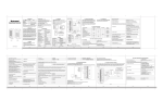
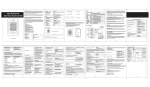
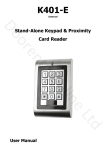
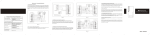
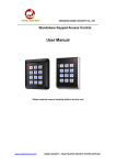
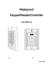
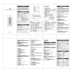
1.Introduction
4.Mounting
1. Attach the rear plate to a single or double gang electrical box or secure to the wall firmly with
at least three flat head screws.
2. When wiring has been completed, attach the front cover to the rear plate.
All programming is done through the keypad. Codes and operating parameters are
stored within the microprocessor and can not be lost due to power failure.
Contents
Do not plug the power supply or transformer into the mains until all wiring has been
completed and the front cover secured.
POWER
Alarm
2.Specifications
J3
2.Specifications
1
3.Important Information
1
4.Mounting
2
1. Programmable Functions
Relay momentary
Relay strike time
Pulse mode,Toggle mode
Change Codes 1 master, 1000 users
5.Wiring
2
2. Programmable Timers
Door relay time 1-99 seconds
Alarm time 1-3 minutes
6.Detailed Programming Guide
4
3. Pulse Mode
Toggle Mode
6.1. User Settings
4
5
6
7
8
9
0
Door detecting switch
Quick Reference Programming Guide
Red
+12V
Black
GND
#
4. Wiring Connections
Electric lock
External bell
External Push Switch
Magnetic Contacts
Alarm
Brown
D_IN
Blue
NO
NO
Electric bolt : NC
COM
NC
Purple
COM
Orange
NC
If holes are to be drilled before mounting onto a wall, check for hidden cables and/or
pipes before drilling. Use safety goggles when drilling or hammering in cable clips.
Every effort has been made to provide accurate information, however slight variations can
occur. We also reserve the right to make changes for product improvement at any time
9.Technical Specification
7
NOTE: please read these instructions carefully before attempting to install
10.Package Listing
ALARM
7
Q
R
1. Alarm output interface (See Figure 1)
2K
1.Unplug the cable harness and connect the
necessary cables(See Figure 3).
2.Tape any wires that are unused.
3.Plug in the cable harness on the PCB
(See Figure 3)
4.attach the front cover(See Figure 4)
ALARMOPEN
D_IN
+12V
GND
Terminal Wire Connector Function
8
ALARM
7
6
OPEN
D_IN
NC
5
NO
RELAY
GND
COM
2. Electric lock interface (See Figure 2)
Figure 1
To exit from the programming mode
*
Note that to undertake the following programming the master user must be logged in
To change the master code
0 New code # New code #
The master code can be 4-6 digits long
To add a PIN user
1 User ID number # PIN #
The ID number is any number between
000 ~ 999.The PIN is any 4-6 digits between
0000 ~ 999999 with the exception of 1234
which is reserved. Users can be added
continuously without exiting programming
mode
To add a card user
1 Read Card #
Cards can be added continuously without
exiting from programming mode
NO
Alarm Switched negative when active
Grey
To delete a PIN or a card user.
2 User ID number # for a PIN user or
2 Read Card # for a card user
Users can be deleted continuously without
exiting from programming mode
COM NO +12V GND PUSH
-
COM
Internal Interface Circuit
NC
Alarm
5.Wiring
6
7
Lock
+
POWER
DC 12V /3A
3.Important Information
8.Resetting To Factory Default Setting
* Master code #
9999 is the default factory master code
Figure 4
5. 12V DC
Metal shell keypad
12 keys with backlight
5
6
7.To Remove The Alarm
-
Common Power Supply
Figure 3
+
6.3. Alarm Settings, Door Detecting
To enter the programming mode
Electric strike: NO
K13
4
6.2. Relay Setting (Pulse mode, Toggle mode)
-
+
Yellow
OPEN
2
3
+
In4007
NC
COM
NO
GND
12V
D_IN
OPEN
ALARM-
1
1
Exit button
Grey
ALARM-
1.Introduction
DC 12V /3A
Current≥200mA
It can store 1 000 users with card and 4-6 digits password codes.It has
one relay output with 3 Amp changeover contacts.
Yellow
To Door EXIT Request Button Then Negative
Brown
To Door Contact Then To Negative
12V
Red
4
GND
Black
(+) 12VDC Positive Regulated Power Input
(-) Negative Regulated Power Input
3
NO
Blue
Door Strike Relay NO
2
COM
Purple
Door Strike Relay Com
1
NC
Orange
Door Strike Relay NC
Figure 2
+
Exit button
Grey
-
Electric bolt
-
+
Electric strike
Yellow
Brown
Door detecting switch
Red
Black
Blue
NO
Purple
COM
Orange
NC
NC
Special Power Supply
To unlock the door
Power on
After all wiring is completed and the unit face plate is attached to the back plate, power on,
the red LED will be flashing.
.1.
To unlock the door for a PIN user
Enter the PIN then press #
To unlock the door for a card user
Present the card
.3.
.2.
6.1. User Settings
To enter the programming mode
To exit from the programming mode
*
Note that to undertake the following programming the master user must be logged in
0 New code # New code #
The master code is any 4-6 digits
To change the master code
Setting the working mode:
Set valid card only users
Set valid card and PIN users
Set valid card or PIN users
3 0 #
3 1 #
3 2 #
To set a user in either card or PIN mode ( 3
To add a PIN user
2 User ID #
To set a card and PIN user in card and PIN mode ( 3 1 # )
* Master code #
9999 is the default factory master code
2
by card only
by card and PIN together
by either card or PIN (default)
# ) (Default setting)
1 User ID number # PIN #
The ID number is any number between
000-999. The PIN is any 4-6 digits between
0000-999999 with the exception of 1234
which is reserved. Users can be added
continuously without exiting from
programming mode as follows:
1 User ID no 1 # PIN # User ID no 2 # PIN #
2 User ID number #
Users can be deleted continuously without
exiting programming mode
To delete a PIN user
To change the PIN of a PIN user
(This step must be done out of
programming mode)
* ID number # Old PIN # New PIN # New PIN #
To add a card user (Method 1)
This is the fastest way to enter cards
using ID number auto generation.
1 Read card #
Cards can be added continuously without
exiting programming mode
To add a card user (Method 2)
This is the alternative way to enter cards
using User ID Allocation. In this method a
User ID is allocated to a card. Only one user
ID can be allocated to a single card.
1 ID number # ReadCard #
To delete a card user by card number.
Note users can be deleted continuously
without exiting programming mode
2 Read Card
To Add a card and PIN user
(The PIN is any 4-6 digits between
0000 & 999999 with the exception of 1234
which is reserved.)
Add the card as for a card user
Press * to exit from the programming mode
Then allocate the card a PIN as follows:
* Read card 1234 # PIN # PIN #
To change a PIN in card and PIN mode
(Method 1) Note that this is done outside
programming mode so the user can
undertake this themselves
* Read Card Old PIN # New PIN # New PIN #
To change a PIN in card and PIN mode
(Method 2) Note that this is done outside
programming mode so the user can
undertake this themselves
* ID number # Old PIN # New PIN # New PIN #
To delete a Card and PIN user just
delete the card
To set a card user in card mode ( 3
8.Resetting To Factory Default Setting
Toggle mode
To delete a card user by user ID. This
option can be used when a user has
lost their card
2 User ID #
0
# )
The operating is the same as adding
and deleting a card user in 3 2 #
To Add and Delete a card user
To delete All users
To delete ALL users. (Note that this is
a dangerous option so use with care)
2 0000 #
4 0 #
Every time a valid tag/card or PIN is
read/input in Toggle Mode, the relay
changes state, which will not turn back until
read card or input PIN again.
Toggle mode
6.3. Alarm Settings, Door Detecting
Alarm output time
To set the alarm output time (1~3 minutes)
Factory default is 1 minute
5 1~3 #
Door Open Detection
Door Open Too Long (DOTL) warning.
When used with an optional magnetic contact or built-in magnetic contact of the lock, if the
door is opened normally, but not closed after 1 minute, the inside buzzer will beep
automatically to remind people to close the door and continue for 1 minute before
switching off automatically.
Door Forced Open warning.
When used with an optional magnetic contact or built-in magnetic contact of the lock, if the
door is opened by force, or if the door is opened after 120 seconds of the electro-mechanical
lock not closed properly, the inside buzzer and alarm output will both operate. The Alarm
Output time is adjustable between 1~3 minutes with the default being 1 minute.
To disable door open detection
(Factory default)
To enable door open detection
Enter the PIN then press #
For a card User
Read card
For a card and PIN user
Read card then enter PIN #
6.2. Relay Setting (Pulse mode, Toggle mode)
Remarks: Reset to factory default, the user's information is still retained.
9.Technical Specification
Supply Voltage
12V DC
Current Consumption
<20mA
Door Relay
3A
Alarm output load
3A
Memory
Non volatile EPROM memory
Codes
1000 Users
6 1 #
Keypad Lockout & Alarm Output options. If there are 10 invalid cards or 10 incorrect
PIN numbers in succession either the keypad will lockout for 10 minutes or the alarm will
operate, depending on the option selected below.
Keypad
12 keys, 3 LED status indicators
EM or EM compatible
Induction Distance
2-6cm
7 0 # (Factory default setting)
Keypad Lockout
7 1 #
Alarm Output
7 2 #
Pulse mode - Door relay time setting
Wiring Connections
.4.
#
.5.
Door open detection
External Alarm
1
2
Tamper Protection
Negative loop, normally closed
3
4
Keypad Housing
Metal
5
Operating Temperature
-40℃ to 60℃ (-40 oF to 140 oF)
6
7
8
9
0
L128 mm×W 82 mm×H 28mm (BC-2000)
L135 mm×W58 mm×H26 mm (K2)
500g
Weight
7.To remove the alarm
To reset the Door Forced Open warning
Read valid card or Master Code #
To reset the Door Open Too Long warning
Close the door or Read valid card or
Master Code #
.6.
User manual
Electric lock
#
10.Package Listing
Name
Model no.
Digital Keypad
BC-2000/K2
Pulse mode (Factory default)
4 1~99 #
The door relay time is between 1~99
seconds, the factory default setting is 5
seconds.
Every time a valid tag/card or PIN is
read/input in Pulse Mode, the relay will
operate, for the pre-set relay pulse time
KP911
Remote Request to Exit
Dimensions
Normal status: No keypad lockout or alarm
(factory default)
Access Control
Card Types
6 0 #
To unlock the door
For a PIN user
To reset to factory default, power off, press * , hold it and power on, release it until hear
three beeps(two short, one long), means reset to factory default successfully.
Qnty
Remark
1
User Manual
BC-2000/K2
1
Diode
1N4007
1 Wall Fixing Plug
Φ6mm×27 mm
4 Used for fixing
Self TapPINg Screws
Φ4mm×27 mm
4
Used for fixing
.7.
Technical 01275 871787
NAVARRA
a
6.Detailed Programming Guide
Puertas Automatic Doors