1
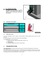
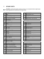
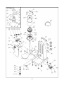
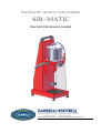
PNEUMATIC CROWN CAPS CORKER
AIR-MATIC
User and maintenance booklet
Via dell’ Artigianato, 70 - 36043 Camisano Vicentino (VI) Italy
Tel. 0444/719402
Fax 0444/719423
www.zambellienotech.it - E-mail: [email protected]
INDEX
1
INTRODUCTION _______________________________________________________________ 5
1.1 HOW TO READ THIS MANUAL _________________________________________________ 5
1.1.1 Purpose and content of the manual _____________________________________________ 5
1.1.2 General warnings ___________________________________________________________ 5
1.1.3 Preserve the manual _________________________________________________________ 5
1.2 MACHINE MANUFACTURER DATA _____________________________________________ 6
1.3 TECHNICAL ASSISTANCE_____________________________________________________ 6
1.4 WARRANTY ________________________________________________________________ 6
2
DESCRIPTION _________________________________________________________________ 7
2.1 DESCRIPTION OF THE MACHINE ______________________________________________ 7
2.1.1 Machine components _______________________________________________________ 7
2.2 TECHNICAL DATA SHEET _____________________________________________________ 8
2.3 PURPOSE OF USE __________________________________________________________ 8
3
TRANSPORTATION ____________________________________________________________ 8
4
SAFETY ______________________________________________________________________ 9
4.1 GENERAL INFORMATION _____________________________________________________ 9
4.2 GENERAL RESIDUAL RISKS ___________________________________________________ 9
4.3 HAZARDOUS MATERIAL RESIDUES ____________________________________________ 9
5
INSTALLATION AND WORKING _________________________________________________ 10
5.1 MOVING AND POSITIONING __________________________________________________ 10
5.2 PREPARATION _____________________________________________________________ 10
5.2.1 Mobile head F regulation _____________________________________________________ 10
5.2.2 Bottle holder L regulation ____________________________________________________ 10
5.2.3 Choosing of the bell M_______________________________________________________ 10
5.3 COMPRESSED AIR CONNECTION _____________________________________________ 10
5.4 SETTING UP _______________________________________________________________ 11
5.5 EVENTUAL CORKING FOR PLASTIC MUSHROOM CORKS _________________________ 11
6
MAINTENANCE _______________________________________________________________ 12
6.1 ORDINARY MAINTENANCE ACTIVITIES (GENERAL INFORMATION) _________________ 12
6.2 ORDINARY MAINTENANCE___________________________________________________ 12
6.3 CLEANING THE MACHINE____________________________________________________ 12
7
SPARE PARTS _______________________________________________________________ 13
8
WASTE DISPOSAL AND DEMOLITION____________________________________________ 15
9
GENERAL SALES CONDITIONS _________________________________________________ 15
2
NAMEPLATE ATTACHED TO THE MACHINE
IMPORTANT:
THIS BOOKLET IS THE PROPERTY OF ZAMBELLI ENOTECH, ANY REPRODUCTION,
EVEN PARTIAL, IS PROHIBITED.
TYPE OF DOCUMENT:
INSTRUCTION MANUAL AND SPARE PARTS
FOR THE FOLLOWING MACHINE: PNEUMATIC CORKER AIR-MATIC
EUROPEAN COMMUNITY LEGISLATION
Instructions taken from the following have been used in composing this manual:
Reference
Directive 2006/42/EC
Title
Machinery Directive
3
EC Declaration of Conformity
The undersigned:
ZAMBELLI ENOTECH srl
Via dell’ Artigianato, 70
36043 – Camisano Vicentino
Vicenza (ITALY)
Assuming full responsibility, declares that the following machine: AIR-MATIC
Type:
Serial number:
Year of construction:
PNEUMATIC CROWN CAPS CORKER
n°________
201__
Complies with:
Machinery Directive 2006/42/EC
NATIONAL REGULATIONS OBSERVED: D.P.R. 27.4.55, N. 547
Legal Administrator Zambelli Enotech:
Responsible for the technical file:
Lorenzo Pillan
Giorgio Pillan
4
1.
INTRODUCTION
First of all we thank you for buying one of our products. Our company is manufacturing wine-producing
and grape-processing equipment for small and medium size wineries.
When creating our items, we always try to ensure they are practical and safe to use, of good quality
and long lasting; to keep them this way, please read the manual carefully.
1.1
HOW TO READ THIS MANUAL
1.1.1 Purpose and content of the manual
This manual describes the PNEUMATIC CORKER AIR-MATIC
This manual was written to allow machine operators to:
know the operational issues related to the machine;
work in safety;
the quality of working process.
Inside this manual, operators will find instructions and information for using and correctly
maintaining the machine, as well as safety and injury regulations.
1.1.2 General warnings
ATTENTION: BEFORE CARRYING OUT ANY OPERATION ON THE MACHINE,
OPERATORS MUST CAREFULLY READ THE INSTRUCTIONS IN THIS MANUAL
AND FOLLOW THEM WHILE EXECUTING ALL OPERATIONS.
ATTENTION: ZAMBELLI ENOTECH is not responsible for:
- damage caused by using the machine for aims different than those
indicated;
- damage caused by unqualified personnel attempting to repair the
machine.
ATTENTION: with regards to some important European Directive norms that regulate
safety at work,
THE PERSON RESPONSIBLE FOR SAFETY in the factory must:
- check that the workers in charge of using the machine are capable of
understanding and applying the basic existing safety norms, in any working
environment.
- provide adequate practical training and ascertain, even through tests, that the
operators are capable of running the machine in a correct and safe way, under
normal working situations and in emergency situations.
1.1.3 Preserve the manual
IT IS MANDATORY TO PRESERVE THE PRESENT MANUAL and all attached documents in
an easily accessible place that is near the machine and known to all users. THE MANUAL IS
AN INTEGRAL PART OF THE MACHINE FOR SAFETY REASONS.
Therefore: - It must be preserved in tact (in all its parts);
- It must accompany the machine until the machine is demolished (even if the
machine is moved, sold, rented, leased, etc.).
If you lose the manual you can order any another copy from the manufacturer or authorized
retailer.
5
1.2
MACHINE MANUFACTURER DATA
Manufacturer:
1.3
ZAMBELLI ENOTECH srl
Via dell’ Artigianato, 70
CAP 36043 CAMISANO VICENTINO (VI) Italy
Tel.: +39 0444 - 719004
Fax: +39 0444 – 719044
e-mail : [email protected]
sito : www. zambellienotech.it
TECHNICAL ASSISTANCE
After-sales service is available to Clients for:
- clarifications and information;
- on-site assistance at the Client’s location, by sending specialized technicians and charging for
transfer costs and labor fees;
- spare parts shipment.
ATTENTION: remember that:
- the Client is under the obligation to always buy original spare parts or
spare parts authorized by the manufacturer;
- the disassembly or assembly of parts must be done by qualified
personnel, following the manufacturer’ s instruction;
- the use of no original parts and defective or incorrect assembly relieve
the manufacturer from any responsibility.
1.4
WARRANTY
ZAMBELLI ENOTECH guarantees that the machine was built in compliance with existing norms, in
particular those related to the health and safety or workers.
The product warranty lasts 12 months; electrical parts are excluded from the warranty.
All expendable items are also excluded from the warranty.
The buyer has the right to substitute defective parts exclusively, after confirmation has been made at
our headquarters or at the Client’s location, with charges applied for transfer costs and labor fees.
Transportation fees for defective parts are at the buyer’s expense and are excluded from the warranty.
Damages derived from mishandling the machine, non-compliance with maintenance norms, as well as
erroneous manoeuvres by operators are excluded from the warranty.
Any tampering with the product, especially with the safety devices, will void the WARRANTY and
relieve the Manufacturer of any responsibility.
No compensation is due for any machine inactivity.
The personnel charged with operating the machine should know this manual well and all
the information relative to safety.
"The improper use" of the machine causes the expiry of the guarantee and the full
assumption of responsibility on the part of the user.
6
2.
DESCRIPTION
2.1
DESCRIPTION OF THE MACHINE
Air-Matic is a crown-caps corker for crown caps Ø26 and Ø29 (optional Ø31) and for plastic mushroom
corks; it’s adjustable in height, with the possibility to cork bottles of various heights and diameters:
- Hmin.: 130 mm
Hmax: 410 mm
- Ømin.: 40 mm
Ømax: 160 mm
The models of corking machine are manufactured in painted version or in stainless steel.
2.1.1 Machine components
The corker is made up of the following machine components as indicated to FIG. I and FIG. II:
A
B
C
D
E
F
G
H
I
K
HANDLE
HOLES FOR ADJUSTMENT
LEFT LEVER
FIXED FRAME
AIR-COMPRESSED CONNECTION
MOBILE HEAD
NUT BOTTLE HOLDER
SUPPORT PLANE
ADJUSTABLE FOOT
INDENTIFYING LABEL
L
M
N
O
P
Q
R
S
T
R.P.
BOTTLE HOLDER
CORKING HEAD
PLEXIGLASS PROTECTION
PLEXIGLASS HINGE
RIGHT LEVER
PNEUMATIC PISTON
LOCKING KNOB BOTTLE HOLDER
LOCKING KNOB HEAD (F)
LOCKING KNOB HEAD (F)
PRESSURE REGULATION (OPTIONAL)
IDENTIFICATION OF
MACHINE COMPONENTS
FRONT SIDE
BACK SIDE
FIG. I
7
R.P. VERSION (OPTIONAL)
On request can be installed a pressure
regulator on the frame of the corker, in
order to control the pressure directly on
the machine.
FIG. II
2.2
TECHNICAL DATA SHEET
DESCRIPTION
Length A
mm
300
Width B
mm
200
Height H
mm
600
Kg
20
Weight
Hourly output *
bot/h
H
500 - 600
A
2.3
B
* approximate value
PURPOSE OF USE
The corker AIR-MATIC series, is made to corking bottles containing liquids such as wine, oil, juice,
milk, etc.
All working operations must be carried out by one single operator.
It is FORBIDDEN to use the machine for:
1. liquids of any type, explosive, inflammable, corrosive, etc.;
2. solid products;
3. animal products;
4. any other use than that for which is was created.
3.
TRANSPORTATION
The corker is delivered complety assembled (except for the handle A) and packed in a carton box
(330x330x580 mm).
Upon delivery, check that the machine was not damaged during transportation and that you receive all
the pieces indicated in the shipping papers. In case of damage, it is mandatory to tell the carrier and to
immediately inform both the manufacturer and the shipper.
8
4.
SAFETY
4.1
GENERAL INFORMATION
The aim of the following chapter is to inform operators of possible risks and safety regulations to keep
in mind when using the machine. However, such regulations must be respected in any working
environment.
Each operator must look after their own health and safety and that of other people present at work.
In particular, operators must:
use the machine correctly following the instructions in the user’s manual;
not remove or modify the safety or signalling devices;
not execute on their own initiative operations not within their competence;
wear clothing and any personal safety devices that comply with existing norms in the work place.
4.2
GENERAL RESIDUAL RISKS
Safety measures have been integrated into the design and manufacture of the machine as much as
possible.
However, risks remain from which operators must be protected.
In order to keep the possibility of accidents to a minimum ( such as
the explosion of the bottle), inviting the operator to maintain MAX
5 atmosphere pressures for crown cap and to MAX 3 atmosphere
for plastic mushroom corks. Therefore, inviting the operator to
maintain the pressures indicated in the adhesive label K.
IT IS REQUIRED to operate the corker using both hands, in
order to eliminate the crushing risk between the neck of the
bottle and the corking head M.
ATTENTION:
♦ DO NOT use the machine for tasks it is not intended for.
♦ DO NOT tamper with the machine and remove safety protections.
♦ DO NOT allow use of the corking machine by children, unauthorized persons, or
persons who do not know how to use it.
4.3
HAZARDOUS MATERIAL RESIDUES
The machine is built with materials that do not present danger or risk to operators.
However, if not properly disposed of, the following can be hazardous to the environment, waste
products that result from processing operations and from maintenance operations. These materials
must be collected and disposed of in accordance with the laws that exist in the country where the
machine is installed.
9
5.
INSTALLATION AND WORKING
5.1
MOVING AND POSITIONING
As first operation, once unpacked the corker, assemble the handle A securing it on the
top of the fixed frame D, using the two screws provided with handle, inside the box.
Moving happens in sure way appealing the corking machine through the handle A.
Once arranged the corking machine on a flat surface, you will proceed to eventual leveling of the
frame by adjusting the feet I.
5.2
PREPARATION
5.2.1 Mobile head F regulation
Regulate the mobile head F in the appropriated position to second to the height of bottle,
leaving trough the top of bottle and bell one space of 2/4 cm approximately.
For make this, unscrew partially the knob T and S and then move the head F up or down
depending on the requirement, insure that the pins places on the head F goes perfectly on the
holes for insertion B. Therefore proceed to block the knob T and S.
5.2.2 Bottle holder L regulation
Once regulated the height of the head, proceed to center the bottle, in case the neck of bottle
was not perfectly aligned with the corking head M.
For make this, unscrew partially the knob R and then regulate the bottle holder L loosening
before the nut G.
Once centered the bottle, block all with the knob R.
5.2.3 Choosing of the bell M
Use the most suitable bell (Ø 26/29/31 mm) depending on the chosen cap for capping.
The replacement happens unscrewing the bell from the corking head and screwing that one in
substitution.
5.3
COMPRESSED AIR CONNECTION
Regulate the gauge of compressor, or of corker (R.P. version), to the pressure indicated on label K
places on the piston Q.
- connect inlet hose from the compressor to the connection E of the corking machine.
- at this point try to action the corking machine, pulling at the same time the two levers C and P to
check the proper functioning.
10
5.4
SETTING UP
ATTENTION: the protection N must be in vertical position towards down, if it results too
much loose, clasp the bolt places on the hinge O.
Operating procedure (see FIG. III)
12345-
position the cap under the bell M. This one remain connected by means of the magnet placed on it;
position the bottle to be capped on the support plane H, putting it to the bottle holder L;
pull at the same time with both hand the two levers C and P;
at the end of the corking release the two levers and remove the bottle corked ;
repeat the operation for each bottle.
FIG. III
5.5
EVENTUAL CORKING FOR PLASTIC MUSHROOM CORKS
Position the cap in vertical position on the mouth of the bottle, pressing it slow. Centering the bottle with
the corking head M, assured that there is a correct space trough the top of the cap and corking head
(approximately 2 cm).
Then, proceed to corking, pulling at the same time the two levers C and P.
11
6.
MAINTENANCE
6.1
ORDINARY MAINTENANCE ACTIVITIES (GENERAL INFORMATION)
For good maintenance:
use only original spare parts, suitable equipment for the task and in good conditions;
respect the frequency of interventions indicated in the manual for programmed maintenance
(preventative and periodic);
good preventative maintenance requires constant attention and continuous surveillance of the
machine. Immediately check the cause of eventual anomalies such as excessive noise,
overheating, leaking fluids, etc. and attempt to remedy.
In case of doubts, consult the constructor or the authorised assistance centre.
6.2
ORDINARY MAINTENANCE
To keep the machine running at full capacity, please follow the maintenance schedule as indicated.
The lack in conformity with the above exonerates the constructor from any and all responsibility in
respect to the guarantee.
NOTE: The indicated frequency refers to normal functioning conditions, i.e. it corresponds to
foreseen and contractually established working conditions.
FREQUENCY
TYPE OF OPERATION
START OF WORKING CYCLE END OF WORKING CYCLE
Safety devices control
X
Valves and pipes efficiency control
X
X
Clean the machine
YEARLY
Joint and soldering control
6.3
CLEANING THE MACHINE
Cleaning the machine permits the removal of eventual incrustations or deposits which may compromise
the optimal functioning of the machine and the processed product.
WARNING: All cleaning and maintenance interventions should be carried out only with
the machine disconnected from compressed air system.
WARNING: waste materials, such as oil, fat, inert material and whatever else should be
collected, recycled or disposed of according to the laws in force in the country in which
the machine is installed.
12
7.
SPARE PARTS
WARNING: to have the machine operate correctly, it is recommended that original spare
parts supplied by the manufacturer are always used.
1
FRAME
10
FIXING KNOB
1/3
HEAD
11
ADJUSTABLE FOOT
2/1
PISTON TUBE
12
HANDLE
2/2A PISTON PLATE LOWER
13
HINGE
2/2B PISTON PLATE HIGHER
14
PLEXIGLASS PROTECTION
2/3
OR PISTON
2/4
NYLON BUSHING
2/5
GASKET SHAFT
B/1
SCREW 8x150
2/6
SHAFT
B/2
NUT M8 cieco
2/7
GASKET PISTON
B/3
SCREW 6x25
3/1
BELL HOLDER
B/4
NUT M6
3/2
BELL Ø26
B/5
WASHER Ø6x18
3/3
BELL Ø29
B/6
SCREW 4x30
3/4
MAGNET HOLDER
B/7
NUT M4 SELF-LOCKING
3/5
MAGNET
B/8
SCREW 4x18
3/6
SPRING
B/9
SCREW 5x55
4/1
VALVE DX 3-WAYS
B/10 NUT M5 SELF-LOCKING
4/2
VALVE SX 5-WAYS
B/11 SCREW 8x10
4/3
VALVE HANDLE
B/12 NUT M18
4/4
INLET FITTING
B/13 SPECIAL WASHER Ø18
4/5
PNEUMATIC SILENCER
B/15 NUT M12
4/6
SWIVEL FITTING
4/7
STRAIGHT FITTING
4/8
TAPERED INLET FITTING
R/1
REGULATOR
4/9
QUICK COUPLING MALE
R/2
LOCKING RING
4/10 QUICK COUPLING FEMALE
R/3
GAUGE
4/11 FITTING WITH MILLED NUT
R/4
REGULATOR SUPPORT
4/12 PIPE
R/5
M-F REDUCER
HARDWARE
OPTIONAL R.P.
5
BOTTLE HOLDER
R/6
SCREW 5x12
6
RUBBER PLANE
R/7
NUT M5
9
FIXING WASHER
R/8
WASHER Ø5
13
14
8.
WASTE DISPOSAL AND DEMOLITION
WASTE DISPOSAL
When using the machine waste materials are generated during processing which must be
collected, recycled or disposed of in accordance with the laws that exist in the country where the
machine is installed. Machine parts which are substituted must also be handled in the same
way.
MACHINE DEMOLITION
When demolishing the machine it is necessary to separate the plastic parts and electrical
components, which must be recycled separately in accordance with existing laws.
With regards to the parts made of metal, simply separate the parts made of steel from those
made of other metals or alloy, so that the parts can arrive and be melted properly at the
recycling center.
ATTENTION: any discharged fluids must not be mixed together, instead, they
must be preserved separately in closed containers to avoid being contaminated
by foreign substances. They must absolutely be disposed of at the appropriate
Waste Disposal Centers.
9.
GENERAL SALES CONDITIONS
TRANSPORTATION
Responsibility of the buyer.
CLAIMS
Claims will not be accepted if more than eight days have passed since
receiving the goods and returns are not accepted without our prior
authorization.
LIMITATIONS
We are not responsible for any damages resulting from unintended use.
Furthermore, the warranty does not cover deficiencies or defects due to
parts that are subject to wear or pieces that are returned disassembled,
mishandled or which were repaired outside our headquarters.
WARRANTY
Our products are thoroughly tried, tested and guaranteed for 12 months
from the date of delivery. Our responsibility under this warranty is limited
to substituting pieces which are eventually found to be defective, after
careful examinations conducted at our headquarters or at the Client’s
location, with charges applied for transfer costs and labor fees.
DISPUTES
The Competent court is the Court of Vicenza (Italy).
TECHNICAL DATA
The technical data in this booklet is informational and not binding. The
company reserves the right to implement changes to its products without
notice.
15
16