1
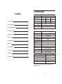
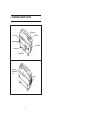
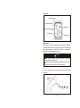
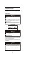
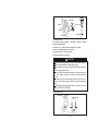
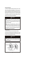
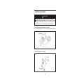
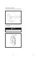
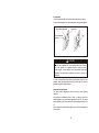
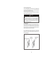
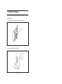
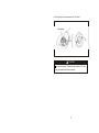
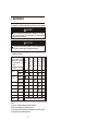
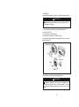
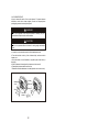
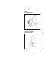
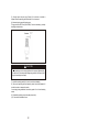
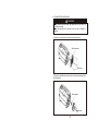
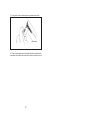
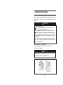
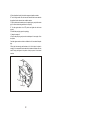
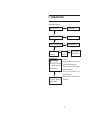
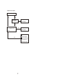
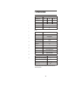
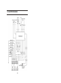
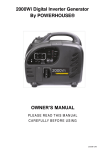
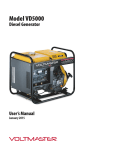
Model VI770
Digital Inverter Generator
User’s Manual
January 2015
PREFACE
Thank you for purchasing a Voltmaster® inverter generator.
This manual covers operation and maintenance of the VI770 generator.
All information in this publication is based on the latest product information
available at the time of approval for printing.
We reserve the right to make changes at any time without notice and without
incurring any obligation.
No part of this publication may be reproduced without written permission.
This manual should be considered a permanent part of the generator and should
remain with it if it is resold.
Pay special attention to statements preceded by the following words;
WARNING
WARNING
CAUTION
WARNING
Failed to properly follow these precautions can result in
property damage, serious injury or DEATH
Read all labels and the owner's manual before operating
this generator.
Operate only in well ventilated areas. Exhaust gas
contains poisonous carbon monoxide, and can be
deadly. Always stop engine before refueling. Wait 5
minutes before restarting.
Check for spilled fuel or leaks. Clean and/or repair
before use.
Keep any sources of ignition away from fuel tank, at all
times.
Indicates a strong possibility of severe personal injury or
death if instructions are not followed.
Indicates a possibility of personal injury or equipment
damage if instructions are not followed. If a problem
should arise, or if you have any questions about the
generator, consult an authorized dealer.
Our generators are designed to give safe and
dependable service if operated according to instructions.
Read and understand the Owner's Manual before
operating the generator. Failure to do so could result in
personal injury or equipment damage.
11. SPECIFICATIONS
CONTENTS
Model
IG770
Rated frequency (Hz)
1. Safety Instructions
1
2. Safety Label Locations
3
3. Component Indentificaction
4
4. Pre-operation Check
5
50
60
230
120
240
Rated current (A)
3.04
5.82
2.92
Rated rotation speed [r/min]
6000
Rated output (kVA)
0.70
Max. output (kVA)
0.77
Engine
KG140
Model Type
5. Starting the Engine
9
Type
Single cylinder, 4 stroke, air-cooled, vertical, OHV
Displacement (BorexStroke)
6. Generator Use
12
37.68ml (40 30mm)
Compression ratio
8.5:1
Rated power [kW(Hp)/(r/min)]
7. Stopping the Engine
8. Maintenance
9. Transporting/Storage
10. Troubleshooting
11. Specifications
16
18
1.00/6000
Rated rotation speed [rpm]
6000
Ignition system
T.C.I
Spark plug
UR5
Starting system
25
27
Recoil starter
Fuel
Automotive unleaded gasoline
Fuel consumption (g/kW.h)
450
Lube oil
CD grade or SAE 10W/30
29
1.55
Fuel tank capacity (L)
12. Electric diagram
60
Rated voltage (V)
30
Continuous running time (hr) (at rated output)
Noise level (zero load-full load) [dB(A)/7m]
3
60-65 *
Overall dimension (LxWxH) [mm(in)]
410 220 360
Dry weight [kg(lbs)]
10.5
*The declared values shall consider uncertainties due to production variation and
measurement procedures.
-
-
1. SAFETY INSTRUCTIONS
WARNING
Operate carefully to ensure safety.
WARNING
Our generators are designed to give safe and
depend-able service if operated according to
instructions.
Read and understand the Owner's Manual before
operating the generator. Failure to do so could result
in personal injury or equipment damage.
WARNING
Exhaust gas contains poisonous carbon monoxide.
Never run the generator in an enclosed area.
Be sure to provide adequate ventilation.
WARNING
The muffler becomes very hot during operation and
remains hot for a while after stopping the engine.
Be careful not to touch the muffler while it is hot.
The engine exhaust system will be heated during
operation and remain hot immediately after stopping
the engine.
To prevent scalding, pay attention to the warning
marks attached to the generator.
WARNING
Gasoline is extremely flammable and explosive under certain conditions.
Refuel in a well ventilated area with the engine stopped.
Keep away from cigarette, smoke and sparks when re-fueling the
generator. Always refuel in a well-ventilated location.
Wipe up spilled gasoline at once.
Usage of generator should be limited in ambient where the risk of fire may
be high.
- -
WARNING
Connections for standby power to a building's electrical system must be
made by a qualified electrician and must comply with all applicable laws and
electrical codes. Improper connections can allow electrical current from the
generator to back feed into the utility lines. Such back feed may electrocute
utility company workers or others who contact the lines during a power
outage, and when utility power is restored, the generator may explode, burn,
or cause fires in the building's electrical system.
WARNING
Always make a pre-operation inspection before you start the engine. You
may prevent an accident or equipment damage.
Place the generator at least 1m(3ft) away from buildings or other
equipment during operation.
Operate the generator on a level surface.
If the generator is tiled, fuel spillage may result.
Know how to stop the generator quickly and understand operation of all
the controls. Never permit anyone to operate the generator without proper
instructions.
Keep children and pets away from the generator when it is in operation.
Keep away from rotating parts while the generator is running.
The generator is a potential source of electrical shocks when misused; do
not operate with wet hands.
Do not operate the generator in rain or snow and do not let it get wet.
- -
2. SAFETY LABEL LOCATIONS
These labels warn you of potential hazards that can cause serious injury. Read
the labels and safety notes and precautions described in this manual carefully.
If a label comes off or becomes hard to read, contact your dealer for a
replacement.
Chock handle
Oil level
Engine switch
Air inlet
Model
Hot caution
Safety caution
- -
3. COMPONENT IDENTIFICATION
Fuel cap lever
Oil filler cap
Chock lever
Maintenance cover
Control panel
Starter grip
Engine switch
Spark plug
maintenance
cover
Muffler
- -
Control panel
Output indicator light
Overload indicator light
Smart switch
Low oil alarm indicator light
AC receptacle
Ground terminal
SMART throttle:
Engine speed is kept at idle automatically when the electrical appliance is
disconnected and it returns to the proper speed to power of the electrical load
when electrical appliance is connected. This position is recommended to
minimize the fuel consumption while in operation.
NOTE
Smart throttle system does not operate effectively if the electrical
appliance requires the big electric power.
When high electrical loads are connected simultaneously turn the smart
throttle switch to the OFF position to re-duce voltage changes.
OFF:
Note: Smart throttle system does not operate. Engine speed is kept at thighspeed lever.
Smart throttle
switch
ON
- -
OFF
4. PRE-OPERATION CHECK
Be sure to check the generator on a level surface with the engine stopped.
1. Check the engine oil level.
CAUTION
Using nondetergent oil or 2-stroke engine oil could shorten the engine's
service life.
Use a high-detergent, premium quality 4-stroke engine oil, certified to
meet or exceed U.S. automobile manufacturer's requirements for API
Service Classification SG/SF.
Select the appropriate viscosity for the average temperature in your area.
SAE Viscosity Grades
Ambient temperature
Engine oil type
-25
-30
10W-30
-15
-40
15W-40
CAUTION
Store and use the oil carefully in order to prevent dust or dirty flowing into
the oil. If oil is overfilled, wipe it up at once.
Never mix different kinds of oil.
Remove and wipe the dipstick with a clean rag. Check the oil level by inserting
the dipstick in the filler hole without screwing it in.
If the oil level is below the end of the dipstick, refill the recommended oil up to the
top of the oil filler neck.
CAUTION
Running the engine with insufficient oil can cause serious engine damage.
The Low Oil Alarm System will automatically stop the engine before the oil
level falls below the safe limit. However, to avoid the inconvenience of an
unexpected shutdown, it is still advisable to visually inspect the oil level
regularly.
- -
Upper lever
Upper limit
Oil rule
Lower limit
Oil filler hole
2. Check the fuel level.
Use automotive gasoline (Unleaded or low-leaded is preferred to minimize
combustion chamber deposits).
If the fuel level is low, refuel the fuel tank until the level as specified.
Never use an oil/gasoline mixture or dirty gasoline.
Avoid getting dirt, dust or water in the fuel tank.
After refueling, tighten the oil rule seurely.
WARNING
CAUTION
Gasoline is extremely flammable and is explosive under certain conditions.
Refuel in a well-ventilated area with the engine stopped.
Do not smoke or alow flames or sparks in the area where the engine is
refueled or where gasoline is stored.
Do not overfill the fuel tank (there should be no fuel above the upper limit
mark). After refueling, make sure the tank cap is closed properly and
securely.
Be careful not to spill fuel when refueling. Spilled fuel or fuel vapor may
ignite, if any fuel is spilled, make sure the area is dry before starting the
engine.
Avoid repeated or prolonged contact with skin or breath-ing of vapor,
KEEP OUT OF REACH OF CHILDREN.
Fuel tank capacity: 1.55L
Fuel filler cap
Open
Upper limit mark
- -
Gasoline containing alcohol
If you decide to use a generator containing alcohol (gasohol), be sure it's octane
rating is at least as high as that recommended by us. There are two types of
gasohol: one containing ethanol, and the other containing methanol. Do not use
gasohol that contains more than 10% ethanol. Do not use gasoline containing
methanol (methyl or wood alcohol) that does not also contain cosolvents and
corrosion inhibitors for methanol. Never use gasoline containing more than 5%
methanol, even if it has cosolvents and corrosion inhibitors.
CAUTION
Fuel system damage or engine performance problems resulting from the
use of fuel that contain alcohol is not covered under the warranty. We cannot
endorse the use of fuels containing methanol since evidence of their
suitability is as yet incomplete.
Before buying fuel from an unfamiliar station, try to find out if the fuel
contains alcohol. If it does, confirm the type and percentage of alcohol used.
If you notice any undesirable operating symptoms while using a gasoline
that contains alcohol, or one that you think contains alcohol, replace it by a
gasoline that you know does not contain alcohol.
3.Check the air cleaner.
Check the air cleaner element to be sure it is clean and in good condition.
Loosen the cover screw and remove the left side maintenance cover. Press the
latch tab on the top of the air cleaner body, remove the air cleaner cover, check
the element. Clean or replace the element if necessary.
CAUTION
Never run the engine without the air cleaner. Rapid engine wear will result
from contaminants, such as dust and dirt, being drawn through the
carburetor, into the engine.
Air filter
Maintenance cover
Air filter element
Air filter cover
Screw
Foam filter
element
-8-
5. STARTING THE ENGINE
CAUTION
Before starting the engine, disconnect the load from the DC terminals.
When starting the generator after adding fuel for the first time or after long
term storage, or after running out of fuel, turn the fuel valve lever to the ''
ON'' position, then wait for 10 to 20 seconds before starting the engine.
1. Turn the fuel cap lever fully clockwise to the ON position.
Note: Turn the fuel cap vent lever to the OFF position when transporting generator.
Fuel cap lever
ON
2. Turn the engine switch to the On position.
ON
OFF
ON
Engine switch
- -
3.Move the choke lever to the START position.
Note: Do not use the choke when the engine is warm or the air temperature is high.
Run
Choke lever
Run
4. Pull the starter grip until resistance is felt, then pull the starter grip briskly toward
the arrow as shown below.
CAUTION
Do not allow the starter grip to snap back, return it slowly by hand.
Starter grip
-
-
5. Move the choke lever to the RUN position after the engine warms up.
Choke lever
Run
Run
CAUTION
If the engine stops and will not restart, check the engine oil level before
troubleshooting in other areas.
High altitude operation
At high altitude, the standard carburetor air-fuel mixture will be excessively rich.
Performance will decrease, and fuel consumption will increase.
High altitude performance can be improved by installing a smaller diameter main
fuel jet in the carburetor and readjusting the pilot screws. If you always operate
the generator at altitudes higher than 1,500m (5,000 feet) above sea level, have
your authorized dealer perform these carburetor modifications.
Even with suitable carburetor jetting, engine horsepower will decrease
approximately 3.5% for each 305m (1,000 feet) increase in altitude. The affect of
altitude on the horsepower will be greater than this if no carburetor modification is
made.
CAUTION
Operation of the generator at an altitude lower than the carburetor is jetted
for may result in reduced performance, overheating, and serious engine
damage caused by an excessively lean air/fuel.
-
-
6. GENERATOR USE
WARNING
To prevent electrical shock from faulty appliances, the generator should
be grounded. Connect a length of heavy wire between the generator's
ground terminal and an external ground source.
Connections for standby power to a building's electrical system must be
made by a qualified electrician and must comply with all applicable laws and
electrical codes. Improper connections can allow electrical current from the
generator to backfeed into the utility lines. Such backfeed may electrocute
utility company workers or others who contact the lines during a power
outage, and when utility power is restored, the generator may explode, burn,
or cause fires in the building's electrical system.
CAUTION
Maximum power would be available for the first 30 minutes.
For continuous operation, do not exceed the rated power.
Do not exceed the current limit specified for any one receptacle.
Do not connect the generator to a household circuit. This could cause the
damage to the generator or to electrical appliances in the house.
Do not modify or use the generator for other purposes than it is intended
for. Also observe the following when using the generator.
A. Do not connect generators in parallel.
B. Do not connect an extension to the exhaust pipe.
When an extension cable is required, be sure to use a tough rubber
sheathed flexible cable.( IEC245
Limit length of extension cables: less than 60 m for cables if 1.5 mm2 and
less than100m for cables of 2.5 mm2.
Keep the generator away from other electric cables or wires such as
commercial power supply lines.
CAUTION
Electrical equipment (including electrical lines and plugs connection)
could not be defective.
-
-
AC applications
1.Start the engine and make sure the output indicator light (green) comes on.
2.Confirm that the appliance to be used is switched off, and plug in the appliance.
Smart switch
Output indicator light(green)
Plug
Overload indicator
light(red)
CAUTION
Be sure that all appliances are in good working
them to the generator. If an appliance begins
becomes sluggish, or stops suddenly, turn off the
immediately. Then disconnect the appliance, and
malfunction.
order before connecting
to operate abnormally,
generator engine switch
examine it for signs of
3. In order to acquire both the best effect and the maximum service life of the
generator. Usually, the new generator should run 20 hours under 50% load, the
generator may reach the best performance.
Output and Overload Indicators
The output indicator light(green)will remain ON during normal operating
conditions.
If the generator is overloaded(in excess of 1.0kVA), or if there is a short in the
connected appliance, the output indicator light(green) will go OFF, the overload
indicator light(red) will go ON and current to the connected appliance will be shut
off.
Stop the engine if the overload indicator light (red) comes ON and investigate the
overload source.
-
-
CAUTION
Before connecting an appliance to the generator, check that it is in good
order, and that its electrical rating does not exceed that of the generator.
Then connect the power cord of the appliance, and start the engine.
CAUTION
Indicator lights (both red and green) may come ON during generator
starting. It is normal if the red indicator light goes off after 4 seconds, if not,
please contact your dealer.
1. Connect the ground terminal.
Grounding terminal
2. Start each engine according to "STARTING THE ENGINE".
When the output indicator light(green)does not light and the overload indicator
light (red) lights instead, set the engine switch to STOP, stop the engine at once
and then start the engine again.
3. Confirm that the equipment to be used is switched off, and insert the plug
of the equipment to be used into the AC receptacle
CAUTION
Confirm that the use equipment to be connected is switched off. When the
equipment to be used is switched on, it will operate suddenly, and injuries or
accidents may be caused.
-
-
4. Switch on the equipment to be used.
In case of overload operation or when trouble occurs for the equipment being
used, the output indicator light(green) will go out, the overload indicator light(red)
will light continuously, and no power will be put out.
At this time, the engine will not stop, so that the engine must be stopped by
setting the respective engine switch to STOP.
CAUTION
When equipment requiring a large starting power, like a motor etc., is used,
the overload indicator light (red) and the output indicator light(green)may
light together for a short time (about 4 sec), but this is no abnormality. After
start of the equipment, the overload indicator light (red) will go out and the
output indicator light(green) will stay lit.
Low oil alarm system
The Low oil alarm system is designed to prevent engine damage caused by an
insufficient amount of oil in the crankcase. Before the oil level in the crankcase
falls below a safe limit, the Low oil alarm system will automatically shut down the
engine (the engine switch will remain in the ON position).
If the low oil alarm system shuts down the engine, the low oil alarm indicator
light(red) will come on when you operate the starter, and the engine will not run. If
this occurs, add engine oil.
Output indicator light (green)
Low oil alarm
indicator (red)
-
-
Overload indicator
light (red)
7. STOPPING THE ENGINE
To stop the engine in an emergency, turn the engine switch to the OFF position.
IN NORMAL USE:
1. Switch off the connected equipment and pull the inserted plug.
Plug
2 .Turn the engine switch to the OFF position.
OFF~
Engine switch
-
-
3.Turn the cap lever fully counterclockwise to the "OFF"position
Fuel cap lever
OFF
CAUTION
Be sure the fuel cap lever, choke and the engine switch are "OFF" when
stopping, transporting and/or storing the generator.
-
-
8. MAINTENANCE
The purpose of the maintenance and adjustment schedule is to keep the generator
in the best operating condition.
WARNING
Shut off the engine before performing any maintena-nce. If the engine
must be run, make sure the area is well ventilated. The exhaust contains
poisonous carbon monoxide gas.
CAUTION
Use genuine our parts or their equivalent. The use of replacement parts
which are not of equivalent qual-ity may damage the generator.
7.1 Maintenance Schedule
REGULAR SERVICE PERIOD(1) Perform at every
indicated month or operating
hour interval,whichever occurs first.
EACH
USE
FIRST EVERY 3 EVERY 6 EVERY
MONTH MONTHS MONTHS YEAR
OR
OR
OR
OR
50HRS 100 HRS 300 HRS
20HRS
ITEM
Engine oil
Check
Change
Air cleaner
Check
Clean
Spark plug
Clean-adjust
Spark arrester
Clean
(2)
Fuel sediment cup Clean
Valve clearance
(3)
(3)
Check-adjust
Fuel tank and strainer Clean
Fuel line
Check
Every 2 years (Replace if necessary)(3)
NOTE:
(1) Log hours of operation to determine proper maintenance.
(2) Service more frequently when used in dusty areas.
(3)These items should be serviced by an authorized dealer, unless the owner has
the proper tools and is mechanically proficient.
1.CHANGING OIL
Drain the oil while the engine is still warm to assure rapid and complete draining.
CAUTION
Confirm if engine lever and ventilation lever of oiling port are turned to the
Off side before the oil drainage.
1. Loosen the cover screw and remove the left side maintenance cover.
2. Remove the oil filler cap.
3. Drain dirty oil into a container thoroughly.
4. Refill with the recommended oil, and check the oil level.
5. Reinstall the left side maintenance cover and tighten the cover screw securely.
Engine oil capacity: 0.15L
Maintenance cover
CAUTION
Screw
Upper level
Dipstick
Oil filler cap
Wash your hands with soap and water after handing used oil.
CAUTION
Please dispose of used motor oil in a manner that is compatible with the
environment. We suggest you take it in a sealed container to your local
service station for reclamation. Do not throw it in the trash or pour it on the
ground.
2. AIR CLEANER SERVICE
A dirty air cleaner will restrict air flow to the carburetor. To prevent carburetor
malfunction, service the air cleaner regularly. Service more frequently when
operating the generator in extremely dusty areas.
WARNING
Do not use gasoline or low flash point solvents for cleaning. They are
flammable and explosive under certain conditions.
CAUTION
Do not run generator without air cleaner for causing engine accelerated
wear.
a. Loosen the cover screw and remove the left side maintenance cover.
b. Press the latch tab on the top of the air cleaner body, and remove the air
cleaner cover.
c. Wash the element in a non-flammable or high flash point solvent and dry it
thoroughly.
d. Soak the element in clean engine oil and squeeze out the excess oil.
e. Reinstall the air cleaner element and the cover.
f. Reinstall the left side maintenance cover and tighten the cover screw securely.
Air filter
Maintenance
cover
Air filter element
Air filter cove
Screw
Foam filter
element
-
-
3. SPARK PLUG SERVICE
RECOMMENTED SPARK PLUG: UR5
To ensure proper engine operation, the spark plug must be properly gapped and
free of deposits.
(1). Remove the spark plug maintenance cover.
Spark plug
maintenance cover
(2). Remove the spark plug cap.
(3). Clean any dirt from around the spark plug base.
(4). Use the wrench to remove the spark plug.
Handle bar
CAUTION
Plug wrench
Spark plug cap
-
-
(5). Visually inspect the spark plug. Discard it if the insulator is cracked or
chipped. Clean the spark plug with a wire brush if it is to be reused.
(6). Measure the plug gap with a feeler gauge.
The gap should be 0.6-0.7mm(0.024-0.028in). Correct as necessary by carefully
bending the side electrode.
Clearance
CAUTION
The spark plug must be securely tightened. An improperly tightened plug
can become very hot and possibly damage the generator. Never use a spark
plug with an improper heat range.
(7). Install the spark plug carefully, by hand, to avoid cross-threading.
(8). After a new spark plug has been seated by hand, it should be tightened 1/2
turn with a wrench to compress its washer.
If a used plug is being reinstalled, it should only require 1/8 to 1/4 turn after being
seated.
(9). Reinstall the spark plug cap on the spark plug securely.
(10). Close the left maintenance cover.
-
-
4. SPARK ARRESTER MAINTENANCE
WARNING
If the generator has been running, the muffler will be very hot. Allow it to
cool before proceeding.
The spark arrester must be serviced every 100 hours to maintain its
efficiency.
(1). Remove the four M5 screws, and remove the muffler protector.
Muffler protector
M5 screw
(2). Remove the there M6 bolts, and remove the muffler, the spark arrester and
the muffler gasket
Muffler gasket
M6 screw
-
-
(3). 3.Use a brush to remove carbon deposits from the spark arrester screen.
Spark arrester
(4). Check the muffler gasket; replace if damaged. Reinstall the muffler gasket, the
spark arrester, the muffler and the muffler protector in the reverse order of removal.
-
-
9. TRANSPORTINT/STORAGE
To prevent fuel spillage when transporting or during temporary storage, the
genera-tor should be secured upright in its normal operating position, with the
engine switch OFF. Turn the cap lever fully counterclockwise to the "OFF"
position.
WARNING
When transporting the generator:
Do not overfill the tank (there should be no fuel in the filler neck)
Do not operate the generator while it is on a vehicle.
Take the generator off the vehicle and use it in a well ventilated place.
Avoid a place exposed to direct sunlight when putting the generator on a
vehicle. If the generator is left in an enclosed vehicle for many hours, high
temperature in-side the vehicle could cause fuel to vaporize resulting in a
possible explosion.
Do not drive on a rough road for an extended period with the generator on
board, if you must transport the generator on a rough road, drain the fuel
from the generator beforehand.
Before storing the unit for an extended period:
1. Be sure the storage area is free of excessive humidity and dust.
2. Drain out the fuel completely.
CAUTION
Gasoline is extremely flammable and explosive under certain conditions.
Do not smoke or allow flames or sparks in the area.
Drain screw
-
-
A. Drain all gasoline from the fuel tank into an approved gasoline container.
B. Turn the engine switch ON, and loosen the carburetor drain screw and drain
the gasoline from the carburetor into a suitable container.
C. With the drain screw loosened remove the spark plug cap, and pull the starter
grip 3 to 4 times to drain the gasoline from the fuel pump.
D. Turn the engine switch to the OFF position, and tighten the drain screw
securely.
E. Reinstall the spark plug cap on the spark plug
3. Change the engine oil.
4. Remove the spark plug and pour about a tablespoon of clean engine oil into
the cylinder.
Crank the engine several revolutions to distribute the oil, then reinstall the spark
plug.
5.Slowly pull the starter grip until resistance is felt. At this point, the piston is
coming up on its compression stroke and both the intake and exhaust valves are
closed. Storing the engine in this position wil help to protect it from internal
corrosion.
Starter grip
-
-
10. TROUBLESHOOTING
When the engine will not start:
NO
Is there fuel in the tank?
Refill the fuel tank.
YES
NO
Is the engine switch on?
Turn the engine switch on.
YES
NO
Is there enough oil in the engine?
Add the recommended oil.
YES
Is there a spark from
the spark plug?
NO
WARNING
Be sure there is no spilled
fuel around the spark pulg.
Spilled fuel may ignite.
Replace the
spark plug.
Still no Take the generator to
spark
an authorized dealer.
To check:
1)Remove the spark plug cap and clean
any dirt from around the spark plug.
2)Remove the spark plug and install the
spark plug in the plug cap.
3)Set the plug side electrode on the
cylinder head to ground.
If the engine still does not
start, take the generator to
an authorized dealer.
4)Pull the recoil starter, sparks should jump
across the gap.
-
-
Appliance does not operate:
Is the output indicator light ON?
NO
YES
NO
Is the overload
indicator light ON?
Take the generator to an
authorized dealer.
YES
Check the electrical appliance or equipment for any
defects.
NO
Take the generator to an
authorized dealer.
Replace the electrical
appliance or equipment
Take the electrical appliance or equipment to an
electrical shop for repair
YES
-
-
11. SPECIFICATIONS
VI770
Model
Rated frequency (Hz)
1
3
4
50
60
60
Rated voltage (V)
230
120
240
Rated current (A)
3.04
5.82
2.92
Rated rotation speed [r/min]
6000
Rated output (kVA)
0.70
Max. output (kVA)
0.77
Engine
5
KG140
Model Type
9
Type
Single cylinder, 4 stroke, air-cooled, vertical, OHV
Displacement (BorexStroke)
12
37.68ml (40 30mm)
Compression ratio
8.5:1
Rated power [kW(Hp)/(r/min)]
16
18
1.00/6000
Rated rotation speed [rpm]
6000
Ignition system
T.C.I
Spark plug
UR5
Starting system
25
27
Recoil starter
Fuel
Automotive unleaded gasoline
Fuel consumption (g/kW.h)
450
Lube oil
CD grade or SAE 10W/30
29
1.55
Fuel tank capacity (L)
30
Continuous running time (hr) (at rated output)
Noise level (zero load-full load) [dB(A)/7m]
3
60-65 *
Overall dimension (LxWxH) [mm(in)]
410 220 360
Dry weight [kg(lbs)]
10.5
*The declared values shall consider uncertainties due to production variation and
measurement procedures.
-
-
12. ELECTRIC DIAGRAM
-30-
Voltmaster is a Wanco brand. Voltmaster, Wanco, and the Voltmaster
and Wanco logos are registered trademarks of Wanco Inc. All other
trademarks are property of their respective owners.
WANCO INC.
5870 Tennyson Street
Arvada, Colorado 80003
800-730-3927
303-427-5700
303-427-5725 fax
www.voltmaster.com
©2015 Wanco Inc. All rights reserved.