1
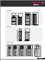
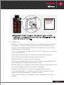
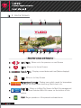
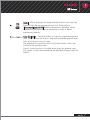
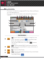
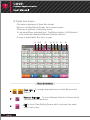
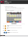
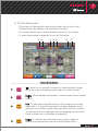
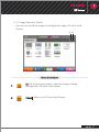
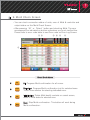
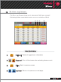
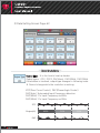
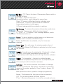
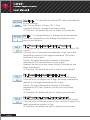
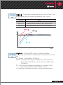
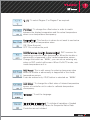
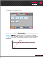
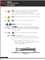
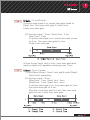
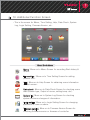
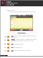
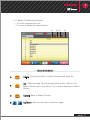
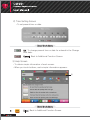
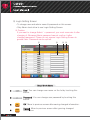
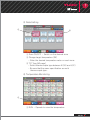
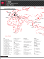
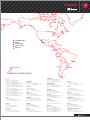
ORIGINAL VERSION
Integrated Control System
• Available to control the temperature and the Sequence Injection Timer
• Available to manage the injection condition for each mold
as well the files and log
• The central control system for multi CW991 through the network
Easy To Use
• User friendly Color Touch LCD equipped with MMI
• To prevent the error setting, the authority code is
provided to each user
Customization
• The optimized zone for the wide variety of injection environment
• Available to provide the special function upon customer's request
Reliability
• 15 criteria internal safety inspections
• CE certification, UL approved
2
목차
1. Check Point before use ·····················
4
1) Appearance Checkup
2) Safety Sign
3) Configurations and Dimensions
4) Caution and Instructions for safety
4-1) Main risk element and prevention
4-2) Safety Measures
4-3) Check list
2. Installation and operation ····················
3. Home Screen ·························
4. Login Screen ··························
5. File Screen ···························
6. Temperature Controller Menu Screen ···············
7. Temperature Monitoring Screen··················
11
12
14
16
18
19
1) Bar View Screen
2) Text View Screen
3) Digital View Screen
3-1) Random Selection Screen
4) Trend View Screen
4-1) Trend View Setup Screen
5) Picture View Screen
5-1) Image Selection Screen
8. Recent Screen ·························
9. Mold Check Screen ·······················
10. Error Log Screen ························
11.Data Setting Screen ·······················
32
33
35
37
1) Data Setting Screen Page #1
2) Data Setting Screen Page #2
3) Data Setting Screen Page #3
4) Data Setting Screen Page #4
12. Timer Screen [Optional] ····················· 49
13. Additional Function Screen ··················· 53
1) Memo Screen
1-1) Memo File Selecting Screen
2) Time Setting Screen
3) Help Screen
4) Data Check Screen
5) Login Setting Screen
6) Firmware Version Screen
14. Operation Examples ······················ 60
15. Controller Specifications ···················· 62
1) Input Specifications
2) Output Specifications
3) Data Communication Protocol
4) System Specifications
5) Timer Specifications [Optional]
6) Environment Specification
3
1. Check Point before use
Only persons with a thorough knowledge of the system's operation and
capabilities should operate the system. Also, keep this user manual with
processor so that he or she can refer to this manual.
ᆞOur policy is one of continuous improvement and we reserve the right to
alter product specifications at any time without giving notice.
ᆞWhilst every effort has been made to avoid errors in the text, the author
and publisher shall not be under any legal liability of any kind in respect
of or arising out of the information contained herein.
Please contact supplier or YUDO representatives to inquiry any questions.
ᆞNo part of this document may be reproduced in any form of by any
means, electronic, mechanical photocopying or otherwise, without prior
written permission of the copyright owner.
1) Appearance Checkup
Check actual controller received differences from contractual configurations.
Check Touch Panel carefully.
Contact supplier or YUDO sales office if you find any damaged or
missing parts.
2) Safely Sign
Sign
Meaning
Sign
Meaning
Must do Grounding
Caution
Danger
Danger of electric shock
Attention High Temperature
3) Configurations and Dimensions
ᆞConfigurations
Model
CW991 PRO
CW991 Slim
CW991 Standard
Max of Zone No.
72
108
24
48
72
96
120
Max. Capacity
Max 150A
Max 225A
Max 100A
Max 100A
Max 150A
Max 200A
Max 225A
Remarks
12.1 inch Touch Panel
12.1 inch Touch Panel
7 inch wide touch panel
12.1 inch Touch Panel
12.1 inch Touch Panel
15 inch Touch Panel
15 inch Touch Panel
※Option: 16 channel timer [CW991 Standard 48zone is 8 channel]
4
CW991 PRO
Unit : ㎜
720
480
510
740
480
108
zone
1150
1370
1600
72
zone
CW991 Slim
420
615
250
24
zone
CW991
1357
1226
CW991
CW991 Standard
CW991
842
610
972
740
72
zone
96
zone
120
zone
CW991
CW991
570
508
CW991
1550
48
zone
699
467
1515
577
345
5
4) Caution and Instructions for safety
4-1) Main risk element and prevention
ᆞThe Risk by electric and electric shock
- Be sure that currents can be flowing on the product because the
controller is using 220Vac or higher and larger voltage in order to
control heaters of mold, so it cause injury and even death when you
touch on the side flowing currents accidently.
- Read all of general safety instructions closely, please be informed
and take prevention measures for all of the accident can be cause
while operating and maintenance.
- Do not handle the controller with wet hands. Otherwise, it can cause
electric shock or severe injury.
- Turning the controller on without notice when a worker maintains
equipment is very dangerous. It can cause severe injury since
currents can be flowing into the worker accidently. Thus, the worker
has to notice maintenance to prevent co-worker to operate
controller.
- Touching on the side flowing currents accidently, it can cause
electric shock and even severe injury or death by flowing currents in
a flash. Thus, please follow below procedures and instructions.
■ After confirming whether the power is off or not, please check residual
electricity on controller by tester.
■ Do not wear the accessory including metal (ring, watch, bracelet and so
on) that can be flowed currents. It is at high risk for electric shock.
- In case of melting a fuse or switching off, the reason can be a
leakage current. If you turn equipment on without notice, not only
the power is off but also the worker could be frosted cause by
leakage current. At this moment, you have to maintain equipment
after disassembling power.
■ Risk part
ᆞConnector of heater output
ᆞConnector of solenoid valve output
ᆞMain power switch
ᆞTerminal and all kinds of cable of controller
ᆞPower supply
ᆞBus-bar covered in side of controller and power cable
6
ᆞA risk by heat
- Controller can be heating during operation. When you handle or
maintain the controller, you can get scalded due to the heating part.
Thus, please handle or maintain after finish to temperature drops to
indoor temperature.
■ Risk part
ᆞHeat sink
ᆞTriac
4-2) Safety measures
ᆞPrecaution for safety
- To operate and maintain controller safely, please be informed well
as to below instructions. Otherwise, you can be frosted by electrical
risk or heat
■ Read all of instruction in this manual and being informed well.
■ After confirming whether the power is off or not, please check residual
electricity on controller by tester.
■ A worker has to notice maintenance to prevent co-worker to operate
controller.
■ Take proper equipment and procedure during the maintenance.
■ Do not do anything while the power is on. Do not wear the accessory
including metal (ring, watch, bracelet and so on) that can be flowed
currents.
■ In case you do maintenance while the power is on, please do work after
making co-workers to be noticed for the work optically/acoustically.
■ Attach the direction board showing an emergency exit in working area.
■ Be sure about emergency shelter and aisle.
■ Remove obstructions on the emergency aisle.
■ Attach the direction board showing emergency shelters in working area.
■ Do not handle equipment when you are drunk or sick.
■ Maintenance without guidance or supervision of manager is restricted.
7
ᆞLocking device
- Install the locking device to reduce losses by accident to the
minimum. Do not damage locking device by yourself.
- During stopping operation, it can shut the function operated out
from the power flowed accidently.
- In case insert power to controller installed locking device, it can
cause serious situation as well as possibility to damage controller.
The locking device has to be handled by trained worker only, and it
has to be confirmed operation of locking device is working properly.
ᆞLocking device & Tag
- The purpose to install locking device is protection for maintenance
worker from the risk caused by unexpected power inserting.
- The purpose of Tag is notification showing maintenance to other
worker in order to get safety from the risk caused by unexpected
power inserting.
- Maintenance worker has to notify the maintenance prior to the
beginning work by tag hanging.
- Install the locking device after stopping operation of controller and
checking if the controller power is off.
ᆞLocking device & Tag Installation guide
- During maintenance, install locking device as follow.
1. Stop the operation if the controller is working.
2. Turn the main power off.
3. Pull the handle of main power switch.
4. Put the locking device in a gap when you pull the handle.
5. To notify maintenance to workers, hang the tag with locking device.
8
Name card(example)
- Maintenance worker consists of one person at least, and the
name/team of maintenance worker who can handle locking device
has to be shown on the tag.
4-3) Check List
ᆞRead all of these instructions before connecting power and turning on
the system. Follow all warnings and instructions mentioned on this
manual. Our company does not take responsibility at all if you use it
Contravening or mishandling.
ᆞIf It is low temperature as less than 10℃ (50℉), Warm up the controller
for more than 30 min.
ᆞNeed regular repair to use the controller continuously and safely.
ᆞSome components have their own product Lifecycle.
ᆞWarranty period is 1 year in normal condition.
ᆞInput socket has danger of electric shock, Must not contact with body
and goods which is applying an electric current.
ᆞBe sure that all of the cables (power cables, thermocouple cables, and
input power cables) are free from wear or damage.
ᆞEstablish locking device in case of maintenance this product.
ᆞTo prevent Breakage or trouble this product, Be sure that the input
power is rated and sequence of phases is correct.
ᆞCheck that the system is completely disconnected from the power
source.
9
ᆞDo not modify the controller or insert in-genuine parts.
ᆞDo not disassemble or modify the controller. It may cause malfunction
or injury.
ᆞCheck that earth/ground connection is in good condition. (Be sure to
do ground connection for any eventuality)
ᆞDo not post device or wiring which is causative of noise around this
product.
ᆞUse controller at vertical stance.
ᆞDo not handle the controller with wet hands.
ᆞWhen water infiltrated, Inspect certainly because there is electric
leakage, danger of fire.
ᆞClean up any water, oil, dirt, cleaning fluids etc. that may have spilled
during a mold change or since the last production run. It may cause
injury.
ᆞKeep out of equipment generating heat.
ᆞWhere not to use this equipment.
- Clean up any dirt, salt content.
- Never allow to install where mechanical vibration and impact are
effective.
- Never allow to install where corrosive or inflammable gas are in
- Keep out of the sun.
- Never allow to install where the temperature changes severely.
- Keep out of inflammable materials.
- Keep out of the electromagnetic wave.
10
2. Installation and operation
1) Make sure that the controller’s main power switch is in the OFF position
prior to connection of the controller to the power source.
2) Check all of the cable connections of the mold (if required).
Check the thermocouple type.
Be sure that all of the cables are free from wear or damage.
3) Check wiring standards whether YUDO standard.
(Power, Thermocouple combined type) or DME standard, etc.
4) Check Power/Thermocouple cables specifications (Connector size, no. of pins).
5) Using an Ohmmeter, check the resistance and isolation of power cables.
Check the open thermocouple cables.
6) Connect power/thermocouple cables to the mold only after the mold is
loaded on the injection molding machine.
7) Connect the controller to the power source if the power source and
controller’s main input power are same.
(Controller’s main input power is shown on the label on the backside of
controller cabinet. If you find the differences between actual main input
power and power shown on the label, contact an authorized
representative. Unless, it may cause damage to controller units and/or
malfunction of controller.)
8) Check that the earth/ground connection is in good condition.
Ensure the system and the mold have the same ground reference.
※ Unless, Noise may cause damage to fuse and/or Triac, and it may cause
injury. Also, short circuit and electric shock accident can be occurred.
9) Switch the controller ON.
10) Enter the password, Then select and load the required Mold file.
11) Verify the target zones On/Off status. Switch the target zones ON if they are not.
12) Enter the target temperatures (SV: Set Value).
13) Select the RUN button to run the system.
14) Verify whether the actual temperatures (PV: Present Value) reach to the
target temperatures (SV).
A guide to Hot Runner Temperature Controller
ᆞCW991 is an advanced multi-channel, high precision hot runner
temperature controller designed for nozzles and manifolds equipped with
personal computer for temperature control.
ᆞWide color screen Touch Panel equipped with MMI (Man Machine
Interface) makes it possible to user friendly interface.
11
3. Home Screen
①
⑤
⑥
②
⑦
⑧
③
⑨
④
⑩
⑪
About the buttons and Status bar
Left / Right : Move on to the previous or next Screen
Home: Move on to Home Screen
Date & Time : Display current date and time(Status displays)
Help: Move on to Help Screen
Temperature Controller : Display menu which needs for temperature
controller like temperature monitoring, Mold check. etc.
Mold File : Move on to Mold File Screen for Mold file management
& open. Show Selected Mold file name on the bottom of this
button.
RUN: Begin operation of the present activated zone
12
Operation Status : Display Operation Status
STOP: Stop all zones.
Login: Move on to Login Screen according to login level.
Display the present logged in user on the bottom of this button.
Timer: Move on to Sequence Injection Timer Setting Screen
controlling Mold valve gate ON/OFF
[Optional Sequence Injection Timer]
13
4. Login Screen
ᆞThe screen according to login level.
ᆞThe Login Methods are
“User”,
“Quick Start”(Without tap password in),
“Admin”,
“User Selection”.
ᆞLogin result is displayed at the bottom right on login button.
①
②
③
④
About the buttons
Quick Start: Use Controller immediately without enter password.
When Login through Quick Start function, use of some
function is limited as login by general user.
User: When displays the keypad button which can login by
general user, Enter user password and click Enter button.
[Password : 1234] Use of some function is limited when login
by general user
14
Admin: When displays the keypad button which can login by
Admin Enter Admin password and click Enter button.
[Password: yudo2010] Admin password is alterable, when
change the password, must remember or take a Memo
password certainly.
User Selection : Another button to login by registered general
user. When press the button, displays registered general user
lists, and choose one of users.
Put password in input box and click Enter button, then use
controller by selected user.
Use of some function is limited when login by general user.
The name of user and password are alterable thereby login by
Admin.
15
5. File Screen
ᆞThis screen is for Mold File management(File Copy, Delete and Rename
etc.) and loading Mold File.
ᆞThis screen provides brief information on the selected file and preview of
image file.
①
② ③ ④ ⑤ ⑥
⑦
⑧
⑨
⑩
⑬
⑪
⑫
⑭
About the buttons
USB: Use for Check & Copy Mold File or Image File in top
folder. This button is reversed
if press Mold Folder
Button and displays Mold File or Image File
If do not insert USB memory, this button
inactivation
becomes
Load: Load the selected Mold File and move onto the next
screen. Shows the selected Mold File name at the bottom of
Mold File button.
New: Create new Mold Folder.
Copy: Copy the selected file. And Cancel Copy mode thereby
selects copy button.
Copy Ready Display :
16
Paste: Through Copy Button, Paste the copied file to selected
Mold folder. To use Paste Mode, Copy Ready Display should
be showed on Copy button.
Rename : Open keyboard by touching Rename button.
Change file name by using keyboard. Only Mold File name can
be change. Select desired Mold File before touching button.
Delete: Delete the selected Mold Folder, Mold File and Image
File. Select desired Folder or File. Delete is possible in
occasion that log in as Admin
Choose Mold Folder :
Choose Mold File :
This button is reversed
if press Mold Folder Button.
Press Mold File Button and
Select in Mold File List
Choose Image File :
Press Image Button and Select
Image File List
Esc: Close File Screen and Move on to Home Screen.
Left/Right : Change Mold Folder.
Mold File : Show Mold File list of the selected Mold Folder.
Image: Preview the Image files of the selected Mold Folder.
Following image formats are available. “.bmp, .jpg, .jpeg
.png”
Error Log: Brief Error Log information on the selected file.
MEMO: Preview the Memos of the selected Mold Folder.
Up/Down : Move on to previous or next file list.
17
6. Temperature Controller Menu Screen
ᆞThis Screen is for Selecting one of Temperature Controller Menu.
①
②
③
④
⑤
⑥
About the buttons
Temperature Monitoring : Move to selecting screen and
Choose one of the Variety Temperature Monitoring (Bar View,
Text View, Digital View, Trend View and Picture View).
Recent File : Move to Recent File Screen which is saved the
recent mold file lists. Load the Mold file on Recent file screen.
Mold Check: Move on the screen which can check controller or
Mold Condition. This button is visible, when login level is
Admin.
Error Log : Move on Error Log Screen to check the past record
Errors.
File: Move on File Screen to load Mold files & file
management.
Additional Function : Move on Additional Function Screen to
set-up Current Time, Memo, Password change.
18
7. Temperature Monitoring Screen
ᆞTo select the desired screen among Text, Bar, Trend, Picture and Digital
View Screen.
①
③
②
④
⑤
About the buttons
Bar View : Move on‘Bar View’Screen which displays
Temperature Monitoring sign as Bar graph form.
Text View : Move on‘Text View’Screen which displays
Temperature Monitoring sign as Text form.
Digital View : Move on‘Digital View’Screen which displays
Temperature Monitoring sign as same form of Box
Trend View : Move on‘Trend View’Screen which displays
Temperature Monitoring sign as connected line.
Picture View : Move on‘Picture View’Screen which displays
Temperature Monitoring sign on background image.
19
1) Bar View Screen
ᆞThe data is displayed in a Bar graph format.
ᆞTo see heating condition through the color of Bar graph even if
separate with touch panel.
ᆞGreen portion of bar shows the range of ideal temperature control,
and Yellow color shows warning section.
ᆞGray portion of bar shows deactivated zone.
ᆞBlack line of bar shows the set values of alarm high and low.
ᆞBlue line of bar shows target temperature.
① ② ③ ④
⑤ ⑥
⑦
⑧
About the buttons
PV: To view actual temperature.
(PV) on text box below bar graph, Bar Graph is not changed in
itself
SV: To view target temperature.
(SV) on text box below bar graph, Bar Graph is not changed in
itself
20
Current: To view current.
(Current) on text box below bar graph, Bar Graph is not
changed in itself.
Output: To view output rate.
(Output) on text box below bar graph, Bar Graph is not
changed in itself.
Boost: By touching‘Boost’button, Operates Boost mode
which is for rising target temperature rapidly.
Boost Mode is operating toward established temperature by
configured time and output rate.
Activate during operation only
Standby: To move Standby mode.
Standby mode is for protecting time loss and saving energy to
keep right temperature. If user wants to take a break, fall
setting temperature to Standby temperature(lower temperature)
and keep the proper temperature. When the configured time is
finished, It returns the original setting temperature.
Activate on standby setting temperature during configured time
only. Activate during operation only.
Up/Down : Move to on next or previous page. Each page
shows 24 zones
Temperature Monitoring : To move and select the different
style of Temperature Monitoring Screen.
ᆞAbbreviation table
No.
Abbreviation
Explanation
1
PV
Present Value, Current Temperature
2
SV
Set Value, Setting Temperature
3
MV
Manipulation Value, Control Valve
21
2) Text View Screen
ᆞThe data is displayed as text values.
ᆞThis screen allows you to view target and actual temperatures, output
rates and currents of heaters.
Furthermore, it allows you to change data setting values.
ᆞMove on to Data Setting Screen from current screen which allows you
to change data setting values by touching any line of zones. The
methods of selecting zones are Individual(Press each zone on the
line), Part(Select button) and All(All button).
ᆞIf zone is deactivated, zone text turns in gray
①
②
③ ④ ⑤
⑥
⑦
⑧
About the buttons
All: Move on to the Data Setting Screen which input the
same value in all zones.
Range of zones : To enter start and finish number of
selecting zone. The finish zone number isn’t over the total
zone number.
Select: To move Data Setting Screen which can enter the same
value from start number to finish number selected in Range of
zones.
22
EX) If you want to change same value from No. 2 zone to
No.24 zone,
① Enter start zone No. 2 in left edit screen.
② Enter finish zone No. 24 in right edit screen.
③ Press Select button.
Boost: By touching ‘Boost’ button, Operates Boost mode
which is for rising target temperature rapidly.
Boost Mode is operating toward established temperature by
configured time and output rate.
Activate during operation only.
Standby: Activate on standby setting temperature during
configured time only. To move Standby mode.
Activate during operation only.
Left/Right : To change displayed zone number on the screen.
By right button, changes to 12→24→48→12 zones.
Up/Down : Move on to next or previous page of this screen
Each page shows 12, 24 or 48 zones.
Temperature Monitoring : To move and select the different
style of Temperature Monitoring Screen.
23
3) Digital View Screen
ᆞThe data is displayed in Same Box format.
ᆞMove on to Data Setting Screen from current screen.
ᆞThere are 4 methods of selecting zones.
※ Individual(Press individual box), Part(Select button), All(All button)
zone select and Random(Random Selection button).
ᆞIf zone is deactivated, Box turns in gray.
① ②③
④
⑤ ⑥ ⑦
⑧
⑨
About the buttons
,
Zone view : To change displayed zone number By press the
button
Random Selection : To move Random Selection Screen which
can select zones randomly.
All: To move Data Setting Screen which can enter the same
value in all zones.
24
Range of zones : To enter start and finish number of selecting
zone. The finish zone number isn’t over the total zone number.
Select: To move Data Setting Screen which can enter the same
value from start number to finish number selected in Range of
zones.
Boost: By touching ‘Boost’ button, Operates Boost mode
which is for rising target temperature rapidly.
Boost Mode is operating toward established temperature by
configured time and output rate.
Activate during operation only.
Standby: Activate on standby setting temperature during
configured time only. To move Standby mode.
Activate during operation only.
Up/Down : Move on to next or previous page of this screen
Each page shows 24 or 48 zones.
Temperature Monitoring : To move and select the different
style of Temperature Monitoring Screen.
25
3-1) Random Selection Screen
ᆞBelow screen is for changing data value.
ᆞYou can choose only one zone or several zones by dragging indicated
zones.
ᆞYellow color boxes are selected zones. If you touch it again, the
selected zone is not activated.
①
② ③
④
About the buttons
Reset
Reset: Selected zones turn to unselected condition.
Ok
Ok: Move to Data Setting Screen for selected zones.
Cancel
Cancel: Back to Digital View Screen.
Up/Down: Move to next 48 zones units.
26
4) Trend View Screen
ᆞYou can monitor Current temperature by line graph.
ᆞYou can select zones by touching Select and Random Selection
button.
ᆞBy pressing check mark at the top of graph, the relevant zone can be
showed /hid.
ᆞMax. 12 zones can be shown on the screen.
ᆞYou can change color of lines and range of Y axis.
①
②
③
④⑤ ⑥
About the buttons
Random Selection: Move on to randomly selection screen.
Max. 12 zones can be selected.
Range of zones : To enter start and finish number of selecting
zone. The finish zone number isn’t over the total zone number.
Select: Only zones from Range of zones(starting zone to
ending zone) are shown. Max. 12 zones can be selected and
they are shown from starting zone in order.
27
Reset
Setup
Reset: Delete all graph on screen and show line graph again.
Set-up: Move on to Trend View Setup Screen for changing
color and range of Y axis.
Temperature Monitoring : To move and select the different
style of Temperature Monitoring Screen.
4-1) Trend View Setup Screen
ᆞYou can change line color and range of Y axis on this Trend View
Screen.
ᆞFor changing line color, touch a checking mark on upper line and
then, lower line. The color will be changed to lower line color.
About the buttons
Ok: Apply changed information on Trend View Screen.
Cancel: Move on to Trend View Screen with ignoring changed
information.
28
5) Picture View Screen
ᆞThis screen is temperature monitoring screen which can check
indicated zone by adding it on background image.
ᆞThis screen allows you to add and delete zones on the image.
ᆞTo select background image by touching File button.
① ②
③ ④ ⑤
⑥
⑦
About the buttons
File
File: Move on to selection screen for selecting Mold image
which you can use background image of current screen.
Image
delete
Delete: Show background image of current screen as an empty
screen.
Add
Delete
Add: To add user selected zones on the image by touching
Add button. If executive keypad for number appears, enter
desired zone number, press enter key and point the location.
To relocate the user selected zone by dragging the zone box.
Equal number can not display overlapping.
Delete: To delete user selected zones on the image by
selecting the target zone and touching Delete button.
29
All
delete
Delete all: To delete all zones on background image.
Left / Right : Move on to Picture View Screen
Max. 6 pages can be shown. You can see current page
number(#1) on bottom of “Picture view”
Temperature monitoring : Move on to changing screen for
different Temperature Monitoring screen.
30
5-1) Image Selection Screen
ᆞYou can choose Mold image for background image of Picture View
Screen.
①②
About the buttons
Ok: By touching this button, selected image is being
background of Picture View Screen.
Cancel: Move on to Picture View Screen.
31
8. Recent Screen
ᆞYou can check saved Mold files and select and load one of them.
ᆞMax. 20 files can be registered. No.1 is latest one.
① ②
③
About the buttons
Load: To load selected Mold file by touching indicated file and
move on to next page. You can check loaded Mold file name
at the bottom of Mold File button.
Close: Move on to Home Screen after closing recent file.
Up/Down: Move on to next or previous page.
32
9. Mold Check Screen
ᆞYou can check connection status of units, error of Mold & controller and
output status on this Mold Check Screen.
ᆞAfter pressing‘All’or‘Select’button and checking Mold, The error
message will be indicated on bottom side when you touch verified line.
Please refer to error code table to see Error code on Error Log Screen.
① ②
③ ④ ⑤
⑥
⑦
About the buttons
All
Select
All: Progress Mold confirmation for all zones.
Selection: Progress Mold confirmation just for selected zone.
Touch Zone number for selecting indicated zone.
Init.
Initialization: Delete Mold identify contents on current screen,
return to initial status for selected zone.
Stop
Stop: Stop Mold confirmation. This button will work during
Mold confirmation.
33
Close
Close: Close Mold Check Screen, back to Home Screen.
Up/Down: Move to next unit of 24 zone.
Zone number: You can select indicated zone number by
touching this button for Mold confirmation. If you touch it
again, the button will be reacted.
34
10. Error Log Screen
ᆞThe Error Log Screen allows you to view errors that have occurred.
ᆞActivating buzzer sound when errors occur on controller or Mold.
① ② ③
④
About the buttons
All
delete
Delete all: Delete all logged error information.
Buzzer off: Turn off the buzzer when activating buzzer sound.
Close
Close: Back to previous screen.
Up/ Down: Move on to previous or next page.
35
ᆞError code table
36
No.
Error message
1
Fuse(Fuse Error)
Fuse Open
2
AC.Er(AC Error)
AC frequency abnormality
3
AL-H(Alarm High)
Actual temperature exceeds set point of alarm high
4
AL-L(Alarm Low)
Actual temperature drops down set point of alarm low
5
HT.Op(Heater Open)
Heater Open
- The heater connection is broken.
6
HT.St(Heater Short)
Shorted Heater – The heater is shorted or
exceeds the maximum rating of the module
7
TC.Re(TC Reverse)
Thermocouple Reversed
- The T/C connection is wired + to - at some point
8
TC.St(TC Short)
Thermocouple Pinched - The T/C is pinched or
the controller thinks it is pinched.
9
TC.Op(TC Open)
Thermocouple (T/C) Open
- The T/C connection is broken
10
Rj.Er(RJC Error)
Internal temperature sensor of controller unit failed
11
AD.Er(ADC Error)
Analog/Digital converter error in controller unit
12
GR.St(GND Fault)
Current detection failed
13
Ca.Er(Calib. Error)
Calibration problem
14
CT.Er(CT Error)
CT current problem
15
Tr.St(Triac Short)
Triac problem occur
Explanations
11. Data Setting Screen
ᆞThis screen is for changing the data of each zones.
ᆞIndividual zone, selected range of zones, all zones and random selected
zones can be changed.
ᆞBlue zone indicator at top middle corner shows the selected zone(s) as
below.
① Individual Zone : [Zone Number]
② All Zones : [Zone ALL]
③ Range of Zones : [Start Zone number ~ End Zone number]
④ Random Selection Zones : Rnadom: 1, 4, 6, 8, …
ᆞCurrent page number(#1) of screen is shown at the top left next to Data
Setting phrase.
ᆞIf all zones are selected, the setting values of zone 1 are displayed.
If a range of zones are selected, the setting values of start zone are
displayed.
ᆞIf random of zones are selected, the setting values of tailender zones are
displayed.
1) Data Setting Screen Page #1
①
②
③
About the buttons
Close
Close: Move on to previous screen by touching“Close”Button.
37
Left/Right : To move the next Data Setting Screen. If you Login
via“Quick start”,“User”or“User Selection”, It wouldn’t
move because there’s no further page.
Up/Down : Move on to the previous or next zone.
Up/Down arrow buttons are visible if an individual zone is
selected
ID No. : IID(Identification) No. Edit box shows identification
number of individual zone.
ID No. Edit box is not editable.
ON/OFF : Activate/Deactivate the selected zone(s) by touching
ON/OFF button.
If this button is On, the selected zone(s) is(are) activated
Name: To change User defined name of zone at Name Edit
box for easy reference.
Name application : To display Name registered in name edit
box instead of zone number on monitoring screen.
If this button is On, Shows the phrase of name edit box on
monitoring screen instead of zone number.
SV(Set Value) : SV means Set temperature, It is edit screen for
entering target temperature.
Stby(Standby) SV : It is edit screen for entering target
Temperature when is activating as Standby mode
This button is just visible, when login level is Admin.
38
Stby Time : It is edit screen for entering operation time when is
activating as Standby mode. This button is just visible, when
login level is Admin.
EX) Stby SV : 150℃, Stby Time : 60mins,
Set Temperature: 200℃
Activate as Standby mode for Stby time.
200℃
Standby SV: 150℃
Standby Time: 1Hour
Time
Boost SV : It is edit screen for entering target temperature
when is activating as boost mode
This button is just visible, when login level is Admin.
Boost Time : It is edit screen for entering operation time when
is activating as boost mode
This button is just visible, when login level is Admin.
Boost MV : It is edit screen for entering output rate when is
activating as boost mode.
This button is just visible, when login level is Admin.
EX) Boost SV : 250℃, Boost Time : 10sec
Boost MV : 100%, Set Temperature: 200℃
Zone 1 : Activate as Boost mode until at the point of Boost SV
Zone 2 : Activate as Boost mode for Boost time.
Boost SV: 250℃
200℃
: Zone1
: Zone2
Boost Time: 10Sec.
Time
39
2) Data Setting Screen Page #2
About the buttons
Output Type : It is the how to heat up heater.
Output types : ZCC, ZCC2, PAC(Auto), PAC(60Hz), PAC(50Hz)
If the button is touched, output type changes in following order.
※ Cannot change while the controller is working
ZCC(Zero Cross Control), PAC(Phase Angle Control)
PAC(Auto): Automated Input Frequency detection
PAC(60Hz): Fix Input Frequency as 60Hz
PAC(50Hz): Fix Input Frequency as 50Hz
ZCC
Output(%)
PAC
40
100%
50%
25%
T/C Type : T/C Type is the type of Temperature Sensor which is
located on Mold.
T/C Types : K(CA) & J(IC) Type
If press the button, could change the sensor type
Check T/C sensor in Mold and tune to individual zone
If sensor isn’t correct, Control would be unstable or
temperature deviation could happen
※ Cannot change while the controller is working.
T/C Reverse : To reverse the polarity of physically upside down
connected Thermocouple (without wiring change)
If“TC.Re”or“TC Reverse”error message appears, switch
T/C Reverse button on.
Buzzer: To decide whether ring the buzzer or not when error
occurs, If turn on button, the buzzer rings.
Buzzer On/Off button is activated, only if all zones are
selected.
Buzzer Time : It is edit screen for entering operation time of
buzzer sound. Buzzer On/Off button is activated, only if all zones
are selected
AL High : It is edit screen for entering the (+)set point to initiate
the alarm. If the actual temperature exceeds set-up
temperature plus AL High set point, AL high function activates.
AL Low : To change the (-)set point to initiate the alarm
If the actual temperature drops below set-up temperature plus
AL Low set point, AL low function activates.
Soft Start : This function prevents from heater coil damage
caused by moisture at fast heat up. Therefore, this function
warms up the system gradually. It has 3 modes, Always, Off
and 1 Time.
When press this button, operation changes progressively
Always : Performance the function as often as operation
OFF : Do not performance Soft Start function
1Time : After permitting power to controller, proceed just once
41
Auto Tuning : To calculate the optimal PID values automatically
by the controller.
Auto Tuning Modes : Always, Off, 1 Time.
If press this button, change mode step by step.
※ Therefore, the default set point is highly recommended
PV Filter : To change duration of average actual temperature.
The actual temperature is the average temperature for the
above given duration.
PID_P(Proportional-Integral-Derivative_Proportional):
To change the set point of proportional bandwidth used in PID
control.
If the set point of proportional bandwidth is high, the actual
temperature reaches to the target temperature (SV) slowly
because of less output.
Unless, the actual temperature reaches to the target
temperature (SV) fast because of more output.
However low set point may cause hunting (fluctuate up and
down periodically).
※ Therefore, the default set point is highly recommended.
PID_I(Proportional-Integral-Derivative_Integral):
To change the set point of Integral time used in PID control.
If the set point of Integral time is high, the actual temperature
reaches to the target temperature (SV) slowly.
Unless, the actual temperature reaches to the target
temperature (SV) fast. However low set point may cause
hunting.
※ Therefore, the default set point is highly recommended.
PID_D(Proportional-Integral-Derivative_Derivative):
To change the set point of Derivative time used in PID control.
If the set point of Derivative time is high, amount of reaction on
rapid temperature variation is high.
※ Therefore, the default set point is highly recommended.
42
A/T Gain : To precisely change the set point of A/T Gain If you
are satisfied with PID values calculated by Auto Tuning
function.
Conditions
Results
Gain < 1.0
Fast response time, but it may cause high hunting.
Gain = 1.0
Same PID values calculated by Auto Tuning function.
Gain > 1.0
Slow response time, but it may cause low hunting.
℃
SV
Time
A/T Mode : To decide PID value in Controller whether
processing automatically calculated auto tuning Time shortly or
not.
A/T Modes : Quick Mode, Full Mode.
Quick: Time that reach target temperature is short than Full
tuning and temperature control can be unstable than
Full tuning.
Full: Time that reach target temperature is long than Quick
tuning and is stable compares Quick tuning.
※ Therefore, the default set point is highly recommended.
43
3) Data Setting Screen Page #3
About the buttons
PV Sync:To determine whether to rise temperature or not after
standing for temperature rise of latest zone. If the button on
the Data Setting Screen page #1 is off, it is inoperative even
though it is turned on.
Heater Sync: This is the function when the temperature sensor
of particular zone has some problem, temporarily refer to
output rate of other zones and put Heater output out. It’s edit
screen to enter the other zone number which is working
ordinarily and heater capacity is the most similar to the zone.
The inputted zone number is saved until power is OFF.
EX) Errors occur on T/C of zone #7
If heater capacity of zone #8 is most similar with zone #7
Setting: After touching the Heater Sync button of zone #7,
input number 8. If the ON/OFF button is OFF on zone #7,
change to ON.
44
℃ / ℉: To select Degree C or Degree F as required.
PV Offset: To change the offset value in order to match
between the display temperature and the actual temperature
when occur temperature discrepancy.
Decimal Point: This function is when do not want to see below
decimal point of temperature value.
ON: Show the point
OFF: Do not show the point
RJC(Reference Junction Compensation): RJC is sensor for
measuring controller inside temperature. When the trouble or
abnormality is happened in this inside temperature sensor,
Change this button as‘MANL’, you can use as entering any
value on RJC control edit screen. When It’s AUTO mode, use
inside temperature as it is.
RJC Preset: This is edit screen for entering temporary value
when the trouble or abnormality is happened in this inside
temperature sensor.
It can be entered only if RJC button is selected as‘MANL’.
RJC Offset: To change the offset value of internal temperature
sensor of controller unit in order to calibrate temperature
discrepancy.
Language: To set the language.
File Init (File Initialization): To initiate all variables of loaded
Mold File. Timer setting values for Sequential Value Gate
Controller are not initiated.
45
Auto Stby: After checking injection signal from Injection
machine, If there are no signal, It shifts into a standby mode
automatically.
In spite of entering the auto standby mode, If Injection signal
is inputted from injection machine, The mode is switched from
Auto Stby(Standby) mode to operation mode. This function is
activated only if optional Timer is set and selected all of zones.
This button is to enter Auto Stby time for entering Auto Stby
mode.
Auto Stby SV: This function is edit screen to input set-up
temperature for entering Auto Stby mode. Auto Stby SV edit
screen is also activated only if optional Timer is set and
selected all of zones.
Auto Stby Time: To change Auto Stby Target Time. The
Function is editable with timer selecting all of zone only.
EX) Auto Stby Wait Time: 10 min, Auto Stby SV: 150℃,
Auto Stby Time: 1 hour
After wait 10 minute when the signal is off, Auto Stby is
operated for an hour.
250℃
Auto Standby
SV: 150℃
Auto Standby
Wait Time: 10Min
Signal OFF
Auto Standby Time: 1Hour,
Signal ON
Time
Update: To upgrade the software. Download the latest
software to USB Memory. Insert Media then wait about 10
seconds until the USB Memory is ready to use. Touch Update
button to upgrade the latest software.
46
4) Data Setting Screen Page #4
About the buttons
Overshoot: Overshoot means in the process of temperature
rising, indicating temperature is exceeded set-up temperature
to the max. This edit screen can control overshoot minutely.
℃
Overshoot
SV
Time
47
M.CTL: To set the maintenance range of set value.
Sensor Range: When the temperature rising, If it does not
move up to present temperature value at a set time, it is
detected as T/C sensor short. At this time, It is the edit screen
to enter the set range of temperature.
Sensor Time: When the temperature rising, If it does not move
up to present temperature value at a set time, it is detected as
T/C sensor short. At this time, It is the edit screen to enter the
set time.
Robot Stop: To stop robot operation when errors occur by
connecting with equipment made by YUDO. To use the
function, all the cables for controller are needed, and the
Buzzer button on Data Setting Screen page #2 has to be set
by ON.
Robot Time: To set the time to stop the operation of YUDO’s
Robot. It is operated after duration(setting value) when errors
occur on controller.
48
12. Timer Screen [Optional]
ᆞThis is screen for ON/OFF control the Mold valve gate.
ᆞTo manually open or close the selected valve gates or all valve gates at
the same time.
ᆞTo reflect to the next shooting out signal, must do save changed values.
①
② ③ ④
⑤ ⑥
⑦
⑧
⑨
⑩
About the buttons
Total time: To set or edit total shooting out time. It’s not related
to Injection opeartion motion, just for referring to enter Delay &
Open time.
All
Select
All: To be ready to open all channels manually.
This sign is displayed the prepared state to manually
open all channels.
Select: To be ready to open selected channels manually.
This sign is displayed the prepared state to manually
open selected channels.
By pressing the channel No button, Select the channel for
manually open. Inverted button means selected this button,
and OFF mode channel can not be selected.
49
Open
Open: Progress selected manually open between manually
open all channels and manually open selected channel If
injection signal is on, this button is not working.
When the mode of channel is OFF, this channel is not working.
Save
Save: Save the setting value of each channel which is currently
set.
Close
Close: To move on to Home Screen without saving.
Up/Down : Move on to next or previous page.
~
Channel No: Be ready to operating channel when manually
open the selected channel. Select and Clear is possible while
operating channel manual open. But, Cannot be selected the
OFF mode channel.
OFF: To switch the valve gate control relevant channel off.
A Mode: To run A mode.
If injection start signal is on, remain valve gate closed for
Delay 1 time, and then open valve gate until injection signal is
off.
EX) Injection signal : 10 sec, Delay1 time : 3 sec
If injection start signal is on, remain valve gate closed
for 3 sec. Then open valve gate for 7 sec.
Finally close valve gate.
50
B Mode : To run B mode.
If injection start signal is on, remain valve gate closed for
Delay1 time. Then open valve gate for Open1 time.
Finally close valve gate.
EX) Injection signal : 10 sec, Delay1 time : 3 sec,
Open1 time : 4 sec
If injection start signal is on, remain valve gate closed
for 3 sec. Then open valve gate for 4 sec.
Finally close valve gate
※ Even though Open1 time is 9 sec, close valve gate when
injection signal is off regardless remaining open 1 time.
C Mode: To run C mode.
To run B Mode (Delay1, Open1 time) and B mode (Delay2,
Open2 time) sequentially.
EX) Injection signal : 20 sec
Delay1 time : 3 sec, Open1 time : 4 sec
Delay2 time : 5 sec, Open2 time : 6 sec
If injection start signal is on, close valve gate for 3 sec,
then open valve gate for 4 sec.
After that, close valve gate for 5 sec, then open valve
gate for 6 sec. Finally close valve gate.
51
Time Unit [1 sec]: To set the time unit of relevant channel in 1
seconds.
Time Unit [0.1 sec]: To set the time unit of relevant channel in 0.1
seconds.
Time Unit [0.01 sec] To change the time unit in floating point
scale which displays one hundredth of 1 sec.
ᆞSolenoid Valve Output voltage
Indicators
Remarks
Solenoid output cable is not connected
Or Fuse Error in Timer
Solenoid output voltage is 24VDC
Solenoid output voltage is 110VAC
Solenoid output voltage is 220VAC
※ Caution!
Be sure that Solenoid valve output voltage is same with input
voltage of Mold solenoid valve.
(If they are not same, it may cause damage or malfunction)
52
13. Additional Function Screen
ᆞThis is the screen for Memo, Time Setting, Help, Data Check, System
Log, Login Setting, Firmware Version, etc.
About the buttons
Memo: Move on to Memo Screen for recording Work history &
others.
Time setting : Move on to Time Setting Screen for setting
present time .
Help: Move on to Help Screen for obtaining some information
of each screen.
Data check: Move on to Data Check Screen for checking some
data (Sensor type, Output of zones, setting temp. etc).
System log: Move on to System Log Screen for checking
system and zone changes of information.
Login setting: Move on to Login Setting Screen for changing
password of users or admin.
Firmware version: Move on to Firmware Version Screen for
checking Software version or firmware of controller.
53
1) Memo Screen
ᆞ To write and edit memo such as work history or other information.
①
② ③
④ ⑤
About the buttons
54
Open
Open: Move on to Memo File Selecting Screen for finding
existing memo.
New
New file: To make a new memo, initialization current signed
memo after checking whether save the memo or not.
Clear
Clear: Clear signed contents.
Save
Save: Save signed memo.
Close
Close: Move on to Additional Function Screen.
1-1) Memo File Selecting Screen
ᆞTo check saved memo list.
ᆞTo open or delete the saved memo.
①
② ③
④
About the buttons
Delete
Ok
Cancel
Delete: Press this button to delete file after selecting file .
OK: After selecting file and pressing this button, Move on to
Memo Screen which you select. The content displays on Memo
Screen.
Cancel: Back to Memo Screen.
Up/Down: Move to the next or previous page.
55
2) Time Setting Screen
ᆞTo set present time or date.
About the buttons
OK: To change present time or date for entered in the Change
time data.
Cancel: Back to Additional Function Screen.
3) Help Screen
ᆞTo obtain simple information of each screen.
ᆞWhen you touch buttons, each simple information appears.
①
About the buttons
Close
56
Close: Back to Additional Function Screen.
4) Data Check Screen
ᆞTo check sensor type, output of zones, setting temp., etc.
ᆞTo change total zone number if you login by admin level.
①
②
③
④
⑤
About the buttons
All: Move to Date Setting Screen for inputting same value on
all zone.
Range of zones: Input starting zone number and finishing
zone number. It cannot be over total zone number.
Select: Move to Data Setting Screen for select partial zone.
Close
Close: Back to Additional Function Screen.
Up/Down: Move to the next or previous zone of 6 unit.
57
5) Login Setting Screen
ᆞTo change user and admin name & password on this screen.
ᆞOnly Admin level allow to use Login Setting Screen.
※ Caution
If you want to change Admin’s password, you must memorize it after
changing it. Because Admin password cannot confirm it after
changing password. Please do not expose Login Setting Screen to
general user. Password can be spilled.
①
②
③ ④
About the buttons
User: You can change user name on the list by touching this
button.
Password: You can change user password by touching this
button.
Ok
Cancel
58
OK: Move to previous screen after saving changed information.
Cancel: Move to previous screen after ignoring changed
information.
6) Firmware Version Screen
ᆞTo check firmware and software version. The displayed number on
screen is indigenous ID of Unit.
①
About the buttons
Close
Close: Back to Additional Function Screen.
59
14. Operation Examples
1) User Login
①
②
① Select Login User - Between User and Admin
② Enter Password - Enter the password according to
selected user.
2) ) Mold File Setting
①
③
②
① Touch Mold File
② Select Mold File - Select the desired file from Mold File list
③ Touch Load Button
60
3) Data Setting
①
②
① Zone ON/OFF - Switch on the desired zone
② Change target temperature (SV)
- Enter the desired temperature value on each zone
③ T/C Type[#2 page]
- Select thermocouple type between K(CA) and J(IC)
- Be sure that the same specification as mold
thermocouple type.
4) Temperature Monitoring
①
① RUN - Operate to raise the temperature
61
15. Controller Specifications
1) Input Specifications
No. of zones
CW991 PRO: 72/108 Zone (12/18 Unit)
CW991 Slim: 24 Zone(4 Unit)
CW991 Standard: 48/72/96/120 Zone (8/12/16/20 Unit)
6 Zone / Unit
Thermocouple Type
TC-K(IEC-584)
TC-J(IEC-584)
Control range
0.00 ~ 500℃ (32 ~ 932℉)
Scan Rate
16.66ms
Scan Accuracy
±0.5% of F/S
Display Resolution Limit
0.1℃ or 1℃
Compensable Temperature variation
±2.0℃ (0 ~ 50℃)
2) Output Specifications
Output Mode
Phase Angle Control, Zero Cross Control
Output Resolution Limit
Phase Angle Control: Approximately 1,000 Resolution
Zero Cross Control: 60Hz/50Hz – 120/100 Resolution
Transmission Output
15A / Zone, 50A / Unit(6 Zone)
Transmission Output period
of renewal
0.02/1sec(Difference Between the output kind)
3) Data Communication Specifications
Protocol
EIA-RS485/422, USB V2.0
Max. number of connection
Max. 21 IDs (include Master). Repeater is required if additional IDs are connected
Communication Method
Half - duplex 2 wire
Communication Speed
19,200/38,400bps
Port Parameters
None Parity, 8 Data, 1 Stop Bit
Communication Distance
About within 1.2Km (Depending on the installation environment)
4) System Specifications
Input
PV Filtering Time
1 ~ 300 sec
Disconnection Detection Up Scale action and exceeding ±5% of input range.
Control
62
Control Method
Point Value Preceding Derivative PID
P Band
0 ~ 500℃ (32 ~ 932℉), If value is 0℃, output changes between On (100%) and Off (0%)
I Time
0 ~ 3,600 sec
D Time
0 ~ 3,600 sec
Hysteresis Range
0.1 ~ 50.0℃ (32.18~122℉)
Self Tuning
Quick, Full Auto Tuning
PID Manual Input
Enter PID value directly or change A/T Gain
Alarm
Range
500℃ (32 ~ 932℉)
Alarm Type
Alarm High (Relative), Alarm Low (Relative)
Hysteresis Range
500℃ (32 ~ 932℉)
Running
RUN/STOP
the controller
BOOST
Run or Stop
Duration, Target Temperature, Output rate
STANDBY
Duration, Target Temperature
Manual Run
Change input (PV) and output
Synchronization
Synchronize PV
Self Diagnosis Diagnosis Method Ground Fault, Triac Short, Heater Open/Short,
Sensor Reverse/Burnout/Short, RJC, ADC, Fuse, AC,
Calibration, CT
5) Timer Specifications [Optional]
Input
Output
Injection Signal
24Vdc, 110Vac, 220Vac
Voltage
85 ~ 264Vac
Relay
DC: 24Vdc(Max 100mA) X 16CH
AC: 110Vac(Max 1A) X 16CH, 220Vac(Max 1A) X 16CH
System Rule Mode
A Mode: Set Delay 1 time
B Mode: Set Delay 1, Open 1 times
C Mode: Set Delay1, Open1, Delay2, Open2 times
Misc
Setting Time Unit : 0.00 ~ 999 sec
Independent running
Detect and display Solenoid Value output voltage
Open all valve gates or individual valve gate.
※ CW991 Standard 48 zone model use 8 channels
6) Environment Specifications
Operating Temperature
0 ~ 50℃ (32 ~ 122℉)
Operating Humidity
20 ~ 90%RH(Non-condensing)
Storage Temperature
-25 ~ 70℃ (-13 ~ 158℉)
Insulation Resistance
500Vdc, Over 20MΩ [Input Power-Field Ground, Input/Output-Field Ground]
Permissive Signal of TC Resistance
Less than 250Ω
Withstand Voltage
1,500Vac, 50/60Hz 1min [Input Power-F/G, Input/Output-F/G, Input/Output-Input Power]
Vibration Resistance
10 ~ 55Hz, Bandwidth 0.75mm, 3 directions 4 swings, 5 min/swing
Impact Resistance
147㎨, 3 directions-3 times
Magnetic Effect
Below 400 AT/m
Warming-up Time
Over 30 min
Net Weight Model
Zone no.
Max. Weight
72
108
24
48
72
96
120
Below Max 175kg
Below Max 240kg
Below Max 80kg
Below Max 115kg
Below Max 135Kg
Below Max 175kg
Below Max 200kg
CW991 PRO
CW991 Slim
CW991 Standard
Remarks
* 6 Zone/Unit: Max 2.6kg
* Input power cable :
Max 1kg/1m
63
EC Declaration of Conformity
according to EC Machinery Directive 2006/42/EC
We herewith declare, Yudo Co., Ltd.
169-4, Gujang-Ri, Paltan-Myun, Hwasung-Si, Gyeonggi-Do,
445-922, Republic of Korea
that the following machine complies with the appropriate basic safety and health
requirements of the EC Directive based on its design and type, as brought into
circulation by us. In case of alteration of the machine, not agreed upon by us, this
declaration will lose its validity.
Machine Description:
Temperature Controller
(Hot Runner Temperature Controller)
Machine Type:
CW991-24, CW991-48, CW991-72,
CW991-96, CW991-108, CW991-120
Serial Number:
-
Applicable
EC Directive: EC Machinery Directive ( 2006/42/EC )
Applicable Harmonized
Standards:
EN ISO 12100:2010
EN 60204-1/AC:2010
Applicable National Technical Standards And Specifications:
Rated input: 220/380 Vac, 3 Phase, 50/60 Hz, 100-225 A
Rated frequency: 50/60 Hz
Temperature Range: 0-500 °C
IP Degree: 20
A.I.C:25-50 kA
Date/ Authorized Signature:
Title of Signatory:
64
(2006/42/EC, Annex II)
The name and address of the person authorized to compile the technical file, who
must be established in the Community;
Contact person:
Company:
Address:
Phone :
Fax:
65
Global Network
FINLAND
NETHERLANDS
GERMANY
RUSSIA
CZECH
POLAND
U.K
FRANCE
SLOVAKIA
ITALY
PORTUGAL
ROMANIA
SPAIN
TURKEY
ISRAEL
EGYPT
SYRIA
KOREA
IRAN
JAPAN
CHINA
TAIWAN
BANGLADESH
INDIA
VIETNAM
THAILAND
MALAYSIA
PHILIPPINES
SINGAPORE
INDONESIA
SOUTH AFRICA
AUSTRALIA
ASIA & OCEANIA
CHINA
YUDO TRADING CO., LTD.
Tel : + 86 769 8539 4466
e-mail : [email protected]
YUDO (HONG KONG) ENTERPRISE CO. LTD.
Tel : + 852 2344 5180
e-mail : [email protected]
YUDO TIANJIN OFFICE
Tel : + 86 22 5839 9351
e-mail : [email protected]
YUDO (SUZHOU) H.R.S. CO. LTD
Tel : + 86 512 6504 8882
e-mail : [email protected]
YUDO (SHANGHAI) OFFICE
Tel : + 86 21 5138 6422
e-mail : [email protected]
YUDO (NINGBO) OFFICE
Tel : + 86 574 8711 3033
e-mail : [email protected]
YUDO (QINGDAO) TRADING CO. LTD.
Tel : + 86 532 8765 1698
e-mail : [email protected]
YUDO (QINGDAO) TRADING CO., LTD
(WEIHAI) OFFICE
Tel : + 86 631 5672 582
e-mail : [email protected]
YUDO (QINGDAO) TRADING CO., LTD
(DAILIAN) OFFICE
Tel : + 86 131 3002 3765
e-mail : [email protected]
KUNSHAN YUDO-SUNS CO LTD.
Tel : + 86 512 5791 0286
66
VIETNAM
HOA VAN HOA COMPANY LTD.
-Hanoi office
Tel : + 84 43 78 77 179
e-mail : [email protected]
-Hochiminh office
Tel : + 84 938 36 23 77
e-mail : [email protected]
JAPAN
YUDO JAPAN CO., LTD.
Tel : + 81 3 5714 4801
e-mail : [email protected]
-Kyushu Office
Tel : + 81 92 473 4808
e-mail : [email protected]
-Nagoya Office
Tel : + 81 52 745 0361
e-mail : [email protected]
INDIA
YUDO HOT RUNNER INDIA PVT. LTD.
Tel : + 91 250 3200922
e-mail : [email protected]
-Delhi Branch Office
Tel : +91 120 454 9076
e-mail : [email protected]
-Pune Branch Office
Tel : +91 7798884634
e-mail : [email protected]
-Chennai Branch Office
Tel : +91 8939625089
e-mail : [email protected]
BANGLADESH
YUDO (BD) PVT. LTD.
Tel : + 88 02 9014 632
e-mail: [email protected]
TAIWAN
YUDO CO., LTD. (TAIWAN BRANCH)
Tel : + 886 2 2205 6677
e-mail: [email protected]
SINGAPORE
YUDO WANCO PTE. LTD.
Tel : + 65 6264 1166
e-mail : [email protected]
PHILIPPINES
YUDO WANCO PHILIPPINES INC
Tel : + 63 949 307 1950
e-mail : [email protected]
THAILAND
YUDO WANCO (THAILAND) CO., LTD.
Tel : +66 2 174 7236~40
e-mail : [email protected]
MALAYSIA
MAWANCO SDN BHD. KL office
Tel : + 60 3 8945 2127
e-mail : [email protected]
MAWANCO SDN BHD. JB office
Tel : + 60 7 8635 704
e-mail : [email protected]
INDONESIA
PT.YUDO INDONESIA
Tel : + 62 21 29083283
e-mail : [email protected]
PT GAYA STEEL
Tel : + 62 21 89832277
e-mail : [email protected]
AUSTRALIA
STM AUSTRALIA PTY. LTD.
Tel : + 61 3 9805 9510
e-mail : [email protected]
NEW ZEALAND
STM SALES LTD.
Tel : + 64 9 8206454
e-mail : [email protected]
SYRIA
SAWAS TRADING GROUP
Tel : + 963 21 2254756
e-mail : [email protected]
ISRAEL
ASI-AFASPEM ISRAEL LTD.
Tel : + 972 4 6802770
e-mail : [email protected]
IRAN
YUDO IRAN
Tel : + 98 21 22066506~7
e-mail : [email protected]
USA
Headquarters
Plant
Subsidiary
Sales Office
Agency
MEXICO
COLOMBIA
PERU
BRAZIL
CHILE
NEW ZEALAND
ARGENTINA
AMERICA & EUROPE & AFRICA
U.S.A.
YUDO INC. (Head Office)
Tel : + 1 614 873 1300
e-mail : [email protected]
-Western Territory (Sales Office)
Tel : + 1 805 480 4922
e-mail : [email protected]
-Central Territory (Sales Office)
Tel : + 1 630 529 7487
e-mail : [email protected]
-Mid-Western Territory (Sales Office)
Tel : + 1 440 834 0167
e-mail : [email protected]
-Southern Region & Peta Business (Sales Office)
Tel : + 1 214 774 4556
e-mail : [email protected]
PORTUGAL
YUDO EU SA.
Tel : + 351 244 570 390
e-mail : [email protected]
FRANCE
YUDO FRANCE
Tel : + 33 2 3261 3218
e-mail : [email protected]
SPAIN
YUDO IBERICA S.L.
Tel : + 34 93 715 81 22
e-mail : [email protected]
U.K.
YUDO (UK) LTD.
Tel : + 44 1989 763423
e-mail : [email protected]
ROMANIA
ROMOULD YUDO ROMANIA
Tel : + 40 213 272 115
e-mail : [email protected]
CZECH
YUDO CZ
Tel : + 420 724 358 612
e-mail : [email protected]
TURKEY
YUDO TURKEY
Tel : + 90 212 320 95 63
e-mail : [email protected]
RUSSIA
OOO YUDIX
Tel : +7 495 723 5221
e-mail : [email protected]
ITALY
YUDO ITALY SH
Tel : + 39 2 99 551 78
e-mail: [email protected]
GERMANY
YUDO GERMANY GmbH.
Tel : + 49 711 707 30370
e-mail : [email protected]
NETHERLANDS
YUDO BENELUX
Tel : + 31 (0)13 5705252
e-mail : [email protected]
SLOVAKIA
YUDO SLOVAKIA s.r.o.
Tel : + 421 335 333 363
e-mail : [email protected]
POLAND
EUROTECH HOLDING Sp. z o.o.
Tel : + 48 22 843 05 79
e-mail : [email protected]
FINLAND
YUDO Nordic Oy
Tel : + 358 3 616 1847
e-mail : [email protected]
BRAZIL
SOLUTION BASE
Tel : + 55 47 3435 0022
e-mail : [email protected]
PAULO ENGENHARIA LTDA.
Tel : + 55 11 3392 5775
e-mail : [email protected]
PERU
TOTALMATRIX S.A.C.
Tel : + 51 1 447 1652
e-mail : [email protected]
CHILE
TOTALMATRIX E.I.R.L
Tel : + 56 2 671 8439
e-mail : [email protected]
MEXICO
YUDO MEXICO S.A de C.V.
Tel : + 52 1 442 285 7120
e-mail : [email protected]
ARGENTINA
Modular Mold Normalizados S.A.
Tel : + 54 11 4756 7272 e-mail : [email protected]
EGYPT
C&C CORPORATION
Tel : + 20 2 2516 7926
e-mail : [email protected]
REPUBLIC OF SOUTH AFRICA
HESTICO PTY. LTD.
Tel : + 27 11 786 5228
e-mail : [email protected]
67
Ver. 1.5 MN CW991 (13. May)