1
UM1017
User manual
STEVAL-MKI062V2 communication protocol
Introduction
The scope of this user manual is to present the communication protocol used between the
STEVAL-MKI062V2 demonstration board (iNEMO™ V2) and the iNEMO SDK (software
development kit). This communication protocol runs on a physical communication channel
based on USB virtual COM, which represents the physical channel used in the
communication between the STEVAL-MKI062V2 and the PC.
The first chapter explains the general frame format and main rules used in the protocol.
The second chapter explains all the frames used in the actual release of the embedded
firmware and software development kit (SDK).
February 2011
Doc ID 18128 Rev 1
1/37
www.st.com
Contents
UM1017
Contents
1
General frame format and protocol rules . . . . . . . . . . . . . . . . . . . . . . . . 6
1.1
1.2
2
1.1.1
Frame control field . . . . . . . . . . . . . . . . . . . . . . . . . . . . . . . . . . . . . . . . . . 7
1.1.2
Length field . . . . . . . . . . . . . . . . . . . . . . . . . . . . . . . . . . . . . . . . . . . . . . . 8
1.1.3
Message ID field . . . . . . . . . . . . . . . . . . . . . . . . . . . . . . . . . . . . . . . . . . . 8
Protocol rules . . . . . . . . . . . . . . . . . . . . . . . . . . . . . . . . . . . . . . . . . . . . . . . 9
STEVAL-MKI062V2 frames . . . . . . . . . . . . . . . . . . . . . . . . . . . . . . . . . . . 11
2.1
STEVAL-MKI062V2 frame types . . . . . . . . . . . . . . . . . . . . . . . . . . . . . . . 11
2.2
Communication control frames . . . . . . . . . . . . . . . . . . . . . . . . . . . . . . . . . 11
2.3
2.4
2/37
Frame format . . . . . . . . . . . . . . . . . . . . . . . . . . . . . . . . . . . . . . . . . . . . . . . 6
2.2.1
iNEMO_Connect . . . . . . . . . . . . . . . . . . . . . . . . . . . . . . . . . . . . . . . . . . 12
2.2.2
iNEMO_Disconnect . . . . . . . . . . . . . . . . . . . . . . . . . . . . . . . . . . . . . . . . 13
2.2.3
iNEMO_Reset . . . . . . . . . . . . . . . . . . . . . . . . . . . . . . . . . . . . . . . . . . . . 13
2.2.4
iNEMO_Enter_DFU_Mode . . . . . . . . . . . . . . . . . . . . . . . . . . . . . . . . . . 14
2.2.5
iNEMO_Trace . . . . . . . . . . . . . . . . . . . . . . . . . . . . . . . . . . . . . . . . . . . . 14
2.2.6
iNEMO_Led_Control . . . . . . . . . . . . . . . . . . . . . . . . . . . . . . . . . . . . . . . 15
Board information frames . . . . . . . . . . . . . . . . . . . . . . . . . . . . . . . . . . . . . 15
2.3.1
iNEMO_Get_Device_Mode . . . . . . . . . . . . . . . . . . . . . . . . . . . . . . . . . . 17
2.3.2
iNEMO_Get_MCU_ID . . . . . . . . . . . . . . . . . . . . . . . . . . . . . . . . . . . . . . 17
2.3.3
iNEMO_Get_FW_Version . . . . . . . . . . . . . . . . . . . . . . . . . . . . . . . . . . . 18
2.3.4
iNEMO_Get_HW_Version . . . . . . . . . . . . . . . . . . . . . . . . . . . . . . . . . . . 18
2.3.5
iNEMO_Identify . . . . . . . . . . . . . . . . . . . . . . . . . . . . . . . . . . . . . . . . . . . 19
2.3.6
iNEMO_Get_AHRS_Library . . . . . . . . . . . . . . . . . . . . . . . . . . . . . . . . . 19
2.3.7
iNEMO_Get_Libraries . . . . . . . . . . . . . . . . . . . . . . . . . . . . . . . . . . . . . . 20
Sensor setting frames . . . . . . . . . . . . . . . . . . . . . . . . . . . . . . . . . . . . . . . 20
2.4.1
iNEMO_Set_Sensor_Parameter . . . . . . . . . . . . . . . . . . . . . . . . . . . . . . 21
2.4.2
iNEMO_Get_Sensor_Parameter . . . . . . . . . . . . . . . . . . . . . . . . . . . . . . 22
2.4.3
iNEMO_Restore_Default_Parameter . . . . . . . . . . . . . . . . . . . . . . . . . . . 22
2.4.4
Accelerometer “Sensor_Parameter” field . . . . . . . . . . . . . . . . . . . . . . . . 23
2.4.5
Accelerometer output data rate . . . . . . . . . . . . . . . . . . . . . . . . . . . . . . . 23
2.4.6
Accelerometer full scale . . . . . . . . . . . . . . . . . . . . . . . . . . . . . . . . . . . . . 24
2.4.7
Accelerometer high-pass filter . . . . . . . . . . . . . . . . . . . . . . . . . . . . . . . . 24
2.4.8
Accelerometer offset . . . . . . . . . . . . . . . . . . . . . . . . . . . . . . . . . . . . . . . 24
Doc ID 18128 Rev 1
UM1017
Contents
2.5
2.6
3
2.4.9
Magnetometer "Sensor_Parameter" field . . . . . . . . . . . . . . . . . . . . . . . 25
2.4.10
Magnetometer output data rate . . . . . . . . . . . . . . . . . . . . . . . . . . . . . . . 25
2.4.11
Magnetometer full scale . . . . . . . . . . . . . . . . . . . . . . . . . . . . . . . . . . . . . 25
2.4.12
Magnetometer operating mode . . . . . . . . . . . . . . . . . . . . . . . . . . . . . . . 26
2.4.13
Magnetometer offset . . . . . . . . . . . . . . . . . . . . . . . . . . . . . . . . . . . . . . . 26
2.4.14
2-axis gyroscope "Sensor_Parameter" field . . . . . . . . . . . . . . . . . . . . . . 26
2.4.15
2-axis gyroscope full scale . . . . . . . . . . . . . . . . . . . . . . . . . . . . . . . . . . . 27
2.4.16
2-axis gyroscope offset . . . . . . . . . . . . . . . . . . . . . . . . . . . . . . . . . . . . . 27
2.4.17
1-axis gyroscope "Sensor_Parameter" field . . . . . . . . . . . . . . . . . . . . . . 27
2.4.18
1-axis gyroscope full scale . . . . . . . . . . . . . . . . . . . . . . . . . . . . . . . . . . . 28
2.4.19
1-axis gyroscope offset . . . . . . . . . . . . . . . . . . . . . . . . . . . . . . . . . . . . . 28
2.4.20
Pressure "Sensor_Parameter" field . . . . . . . . . . . . . . . . . . . . . . . . . . . . 28
2.4.21
Pressure sensor output data rate . . . . . . . . . . . . . . . . . . . . . . . . . . . . . 29
2.4.22
Pressure sensor offset . . . . . . . . . . . . . . . . . . . . . . . . . . . . . . . . . . . . . . 29
2.4.23
Temperature "Sensor_Parameter" field . . . . . . . . . . . . . . . . . . . . . . . . . 29
2.4.24
Temperature sensor offset . . . . . . . . . . . . . . . . . . . . . . . . . . . . . . . . . . . 29
Acquisition sensor data frames . . . . . . . . . . . . . . . . . . . . . . . . . . . . . . . . 30
2.5.1
iNEMO_Set_Output_Mode . . . . . . . . . . . . . . . . . . . . . . . . . . . . . . . . . . 31
2.5.2
iNEMO_Get_Output_Mode . . . . . . . . . . . . . . . . . . . . . . . . . . . . . . . . . . 33
2.5.3
iNEMO_Start_Acquisition . . . . . . . . . . . . . . . . . . . . . . . . . . . . . . . . . . . 33
2.5.4
iNEMO_Stop_Acquisition . . . . . . . . . . . . . . . . . . . . . . . . . . . . . . . . . . . 35
Error code . . . . . . . . . . . . . . . . . . . . . . . . . . . . . . . . . . . . . . . . . . . . . . . . . 35
Revision history . . . . . . . . . . . . . . . . . . . . . . . . . . . . . . . . . . . . . . . . . . . 36
Doc ID 18128 Rev 1
3/37
List of tables
UM1017
List of tables
Table 1.
Table 2.
Table 3.
Table 4.
Table 5.
Table 6.
Table 7.
Table 8.
Table 9.
Table 10.
Table 11.
Table 12.
Table 13.
Table 14.
Table 15.
Table 16.
Table 17.
Table 18.
Table 19.
Table 20.
Table 21.
Table 22.
Table 23.
Table 24.
Table 25.
Table 26.
Table 27.
Table 28.
4/37
Frame type list . . . . . . . . . . . . . . . . . . . . . . . . . . . . . . . . . . . . . . . . . . . . . . . . . . . . . . . . . . . 7
Frame version list . . . . . . . . . . . . . . . . . . . . . . . . . . . . . . . . . . . . . . . . . . . . . . . . . . . . . . . . . 8
QoS list . . . . . . . . . . . . . . . . . . . . . . . . . . . . . . . . . . . . . . . . . . . . . . . . . . . . . . . . . . . . . . . . . 8
Communication control frames . . . . . . . . . . . . . . . . . . . . . . . . . . . . . . . . . . . . . . . . . . . . . . 11
Board information frames . . . . . . . . . . . . . . . . . . . . . . . . . . . . . . . . . . . . . . . . . . . . . . . . . . 15
Sensor setting frames . . . . . . . . . . . . . . . . . . . . . . . . . . . . . . . . . . . . . . . . . . . . . . . . . . . . . 20
Sensor_Type field . . . . . . . . . . . . . . . . . . . . . . . . . . . . . . . . . . . . . . . . . . . . . . . . . . . . . . . . 23
Accelerometer Sensor_Parameter field . . . . . . . . . . . . . . . . . . . . . . . . . . . . . . . . . . . . . . . 23
Accelerometer output data rate and fields . . . . . . . . . . . . . . . . . . . . . . . . . . . . . . . . . . . . . 23
Accelerometer full scale and fields . . . . . . . . . . . . . . . . . . . . . . . . . . . . . . . . . . . . . . . . . . . 24
Accelerometer high-pass filter setting. . . . . . . . . . . . . . . . . . . . . . . . . . . . . . . . . . . . . . . . . 24
Magnetometer Sensor_Parameter field . . . . . . . . . . . . . . . . . . . . . . . . . . . . . . . . . . . . . . . 25
Magnetometer output data rate field . . . . . . . . . . . . . . . . . . . . . . . . . . . . . . . . . . . . . . . . . . 25
Magnetometer full scale field . . . . . . . . . . . . . . . . . . . . . . . . . . . . . . . . . . . . . . . . . . . . . . . 25
Magnetometer operating mode setting . . . . . . . . . . . . . . . . . . . . . . . . . . . . . . . . . . . . . . . . 26
2-axis gyroscope (pitch/roll) Sensor_Parameter field . . . . . . . . . . . . . . . . . . . . . . . . . . . . . 27
2-axis gyroscope full scale field . . . . . . . . . . . . . . . . . . . . . . . . . . . . . . . . . . . . . . . . . . . . . 27
1-axis gyroscope (yaw) Sensor_Parameter field . . . . . . . . . . . . . . . . . . . . . . . . . . . . . . . . 28
2-axis gyroscope full-scale field . . . . . . . . . . . . . . . . . . . . . . . . . . . . . . . . . . . . . . . . . . . . . 28
Pressure Sensor_Parameter field. . . . . . . . . . . . . . . . . . . . . . . . . . . . . . . . . . . . . . . . . . . . 28
Pressure sensor output data rate field . . . . . . . . . . . . . . . . . . . . . . . . . . . . . . . . . . . . . . . . 29
Temperature Sensor_Parameter field . . . . . . . . . . . . . . . . . . . . . . . . . . . . . . . . . . . . . . . . 29
Acquisition sensor data frames. . . . . . . . . . . . . . . . . . . . . . . . . . . . . . . . . . . . . . . . . . . . . . 30
Calibrated and raw fields . . . . . . . . . . . . . . . . . . . . . . . . . . . . . . . . . . . . . . . . . . . . . . . . . . 31
Acquisition rate . . . . . . . . . . . . . . . . . . . . . . . . . . . . . . . . . . . . . . . . . . . . . . . . . . . . . . . . . . 31
Output interface . . . . . . . . . . . . . . . . . . . . . . . . . . . . . . . . . . . . . . . . . . . . . . . . . . . . . . . . . 32
Error code field . . . . . . . . . . . . . . . . . . . . . . . . . . . . . . . . . . . . . . . . . . . . . . . . . . . . . . . . . . 35
Document revision history . . . . . . . . . . . . . . . . . . . . . . . . . . . . . . . . . . . . . . . . . . . . . . . . . 36
Doc ID 18128 Rev 1
UM1017
List of figures
List of figures
Figure 1.
Figure 2.
Figure 3.
Figure 4.
Figure 5.
Figure 6.
Figure 7.
Figure 8.
Figure 9.
Figure 10.
Figure 11.
Figure 12.
Figure 13.
Figure 14.
Figure 15.
Figure 16.
Figure 17.
Figure 18.
Figure 19.
Figure 20.
Figure 21.
Figure 22.
Figure 23.
Figure 24.
Figure 25.
Figure 26.
Figure 27.
Figure 28.
STEVAL-MKI062V2 communication architecture . . . . . . . . . . . . . . . . . . . . . . . . . . . . . . . . . 6
General frame format . . . . . . . . . . . . . . . . . . . . . . . . . . . . . . . . . . . . . . . . . . . . . . . . . . . . . . 6
Frame control field . . . . . . . . . . . . . . . . . . . . . . . . . . . . . . . . . . . . . . . . . . . . . . . . . . . . . . . . 7
Data or control frame transmission without an acknowledgement . . . . . . . . . . . . . . . . . . . . 9
Data or control frame transmission with an acknowledgement. . . . . . . . . . . . . . . . . . . . . . . 9
"Bad" data or control frame transmission with no-acknowledgement . . . . . . . . . . . . . . . . . 10
iNEMO_Connect frames . . . . . . . . . . . . . . . . . . . . . . . . . . . . . . . . . . . . . . . . . . . . . . . . . . . 12
iNEMO_Disconnect frames . . . . . . . . . . . . . . . . . . . . . . . . . . . . . . . . . . . . . . . . . . . . . . . . 13
iNEMO_Reset frames . . . . . . . . . . . . . . . . . . . . . . . . . . . . . . . . . . . . . . . . . . . . . . . . . . . . . 13
iNEMO_Enter_DFU_Mode frames . . . . . . . . . . . . . . . . . . . . . . . . . . . . . . . . . . . . . . . . . . . 14
iNEMO_Trace frames . . . . . . . . . . . . . . . . . . . . . . . . . . . . . . . . . . . . . . . . . . . . . . . . . . . . . 14
iNEMO_Led_Control frames. . . . . . . . . . . . . . . . . . . . . . . . . . . . . . . . . . . . . . . . . . . . . . . . 15
iNEMO_Get_Device_Mode frames . . . . . . . . . . . . . . . . . . . . . . . . . . . . . . . . . . . . . . . . . . 17
iNEMO_Get_MCU_ID frames. . . . . . . . . . . . . . . . . . . . . . . . . . . . . . . . . . . . . . . . . . . . . . . 17
iNEMO_Get_FW_Version frames. . . . . . . . . . . . . . . . . . . . . . . . . . . . . . . . . . . . . . . . . . . . 18
iNEMO_Get_HW_Version frames . . . . . . . . . . . . . . . . . . . . . . . . . . . . . . . . . . . . . . . . . . . 18
iNEMO_Identify frames. . . . . . . . . . . . . . . . . . . . . . . . . . . . . . . . . . . . . . . . . . . . . . . . . . . . 19
iNEMO_Get AHRS_Library frames . . . . . . . . . . . . . . . . . . . . . . . . . . . . . . . . . . . . . . . . . . 19
iNEMO_Get_Libraries frames. . . . . . . . . . . . . . . . . . . . . . . . . . . . . . . . . . . . . . . . . . . . . . . 20
iNEMO_Set_Sensor_Parameter frames. . . . . . . . . . . . . . . . . . . . . . . . . . . . . . . . . . . . . . . 21
iNEMO_Get_Sensor_Parameter frames . . . . . . . . . . . . . . . . . . . . . . . . . . . . . . . . . . . . . . 22
iNEMO_Restore_Default_Parameter frames . . . . . . . . . . . . . . . . . . . . . . . . . . . . . . . . . . . 22
Parameter_Value fields for accelerometer HPF setting . . . . . . . . . . . . . . . . . . . . . . . . . . . 24
Parameter_Value fields for magnetometer operating mode setting . . . . . . . . . . . . . . . . . . 26
iNEMO_Set_Output_Mode frames . . . . . . . . . . . . . . . . . . . . . . . . . . . . . . . . . . . . . . . . . . . 31
iNEMO_Get_Output_Mode frames. . . . . . . . . . . . . . . . . . . . . . . . . . . . . . . . . . . . . . . . . . . 33
iNEMO_Start_Acquisition frames . . . . . . . . . . . . . . . . . . . . . . . . . . . . . . . . . . . . . . . . . . . . 33
iNEMO_Stop_Acquisition frames . . . . . . . . . . . . . . . . . . . . . . . . . . . . . . . . . . . . . . . . . . . . 35
Doc ID 18128 Rev 1
5/37
General frame format and protocol rules
1
General frame format and protocol rules
1.1
Frame format
UM1017
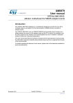
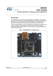
This section explains the format of the frame used in the STEVAL-MKI062V2
communication protocol. The STEVAL-MKI062V2 exchanges data and commands with the
PC GUI through a physical communication channel based on USB virtual COM. Each
frame, described below, represents the payload of a USB frame.
Figure 1.
STEVAL-MKI062V2 communication architecture
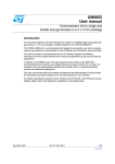
The frames are described as a sequence of fields in a specific order. All frame formats are
depicted in the order in which they are passed to the USB driver, from left to right. Bits within
each field are numbered from k-1 (leftmost and most significant) to 0 (rightmost and least
significant), where the length of the field is k bits.
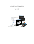
The frame format is composed of a header and an optional payload. The general frame is
formatted as illustrated in Figure 2. The header is composed of three mandatory (M) fields,
each of which is 1 byte in length, while the payload is an optional field whose maximum
length is 61 bytes. See LF/MF field in the following section to exceed this limit.
Figure 2.
6/37
General frame format
Doc ID 18128 Rev 1
UM1017
1.1.1
General frame format and protocol rules
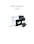
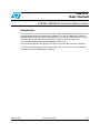
Frame control field
The frame control field is 1 byte in length and contains information defining the frame type
and other control flags. The frame control field is formatted as illustrated in Figure 3.
Figure 3.
Frame control field
The frame type subfield is 2 bits in length and is set to one of the values listed in Table 1.
Table 1.
Frame type list
Value
Frame type
00
CONTROL
01
DATA
10
ACK
11
NACK
The ACK subfield is 1 bit in length and specifies whether an acknowledgement is required
from the recipient on receipt of a DATA or CONTROL frame. If this field is set to one, the
recipient sends an acknowledgment frame only if, upon reception, the frame passes all
required levels of filtering. If this subfield is set to zero, the recipient device does not send an
acknowledgment frame. It is possible to embed a payload in an acknowledgment frame
(piggybacking) to send useful information to the transmitter and avoid further transactions.
When the ACK field is set to one, and if, upon reception the frame doesn't pass the required
level of filtering, the recipient sends a no-acknowledgment frame (NACK), whose payload is
an error code (e.g. unsupported command, value out of range,…). In the ACK and/or NACK
frames the ACK field is set to zero and ignored upon reception.
The LF/MF (last fragment / more fragment) subfield is 1 bit in length and it is used for
fragmentation and reassembling. This field is set to zero to indicate a single frame or the last
frame of a multiple-frame transaction. This field is set to 1 to indicate that other frames
follow, all belonging to the same transaction. In the ACK and NACK frames (with or without
payload) fragmentation is not supported and this subfield is set to zero in the transmission of
ACK and NACK frames and ignored upon reception.
Doc ID 18128 Rev 1
7/37
General frame format and protocol rules
UM1017
The frame version subfield is 2 bits in length and is set to “00” at this time. Values
concerning future versions are “reserved for future use” (RFU) as listed in Table 2.
Table 2.
Frame version list
Value
Frame version
00
Version 1.0
01
10
RFU
11
The QoS (Quality of Service) subfield is 2 bits in length and is set to one of the values listed
in Table 3. This subfield allows the application to exchange and process data and control
frames with different priorities.
Table 3.
1.1.2
QoS list
Value
QoS
00
Normal priority
01
Medium priority
10
High priority
11
RFU
Length field
The length field is 1 byte in length and contains the number of bytes that follow. Admitted
values are in the range 1 to 62.
1.1.3
Message ID field
The message ID is 1 byte in length and contains an identifier of the user application
messages. See Section 2.2 and the following for further details.
8/37
Doc ID 18128 Rev 1
UM1017
1.2
General frame format and protocol rules
Protocol rules
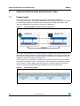
There are two types of transactions, according to whether the DATA or CONTROL frame is
acknowledged or not.
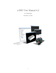
A DATA or CONTROL frame with the ACK subfield of its frame control field set to zero is not
acknowledged by its intended recipient. The originating device (PC or iNEMO board)
assumes that the transmission of the frame was successful. The message sequence chart
in Figure 4 shows the scenario for transmitting a single DATA or CONTROL frame from an
originator to a recipient without requiring an acknowledgement.
Figure 4.
Data or control frame transmission without an acknowledgement
5HFLSLHQW
2ULJLQDWRU
'DWDRU&RQWURO)UDPHZLWK
$FN VXEILHOGVHWWR
!-V
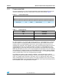
A DATA or CONTROL frame transmitted with the ACK subfield of its frame control field set to
one is acknowledged by the recipient. If the intended recipient correctly receives the frame,
it generates and sends an ACK frame containing the same message ID from the DATA or
CONTROL frame that is being acknowledged. It is also possible to include a payload in the
ACK frame to transfer useful data from the recipient to the originator. The message
sequence chart in Figure 5 shows the scenario for transmitting a single DATA or CONTROL
frame from an originator to a recipient with an acknowledgement.
Figure 5.
Data or control frame transmission with an acknowledgement
2ULJLQDWRU
5HFLSLHQW
'DWD RU &RQ
WURO )UDPH Z
LWK
$FN VXEILHOG
VHW WR $&. )UDPH
SD\ORDG
XW
ZLWK RU ZLWKR
!-V
Doc ID 18128 Rev 1
9/37
General frame format and protocol rules
UM1017
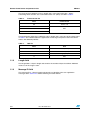
If the frame received does not pass all the required filtering rules, the recipient generates
and sends a NACK frame containing the same message ID from the DATA or CONTROL
frame that is being acknowledged and contains the error code. The message sequence
chart in Figure 6 shows the scenario for transmitting a single "bad" DATA or CONTROL
frame from an originator to a recipient with a no-acknowledgement.
Figure 6.
"Bad" data or control frame transmission with no-acknowledgement
2ULJLQDWRU
5HFLSLHQW
³%$'´ 'DWD
RU &RQWURO )U
DPH
ZLWK $FN VX
EILHOG VHW WR
ZLWK HUURU
1$&. )UDPH
FRGH
!-V
10/37
Doc ID 18128 Rev 1
UM1017
STEVAL-MKI062V2 frames
2
STEVAL-MKI062V2 frames
2.1
STEVAL-MKI062V2 frame types
The frames used in the STEVAL-MKI062V2 are classified in four types:
2.2
1.
Communication control frames
2.
Board information frames
3.
Sensor setting frames
4.
Acquisition sensor data frames
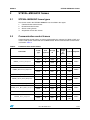
Communication control frames
Communication control frames are frames originated by the software PC (SDK or GUI) and
used to send specific commands to the iNEMO board. All the communication control frames
are listed in Table 4.
Table 4.
Communication control frames
Ack
Message
QoS
required
ID
Payload
length
Payload Originator
(in
bytes)
Commands
Frame
type
iNEMO_Connect
CONTROL
Y
0x00
N
0
ACK
N
0x00
N
0
NACK
N
0x00
N
1
CONTROL
Y
0x01
N
0
ACK
N
0x01
N
0
NACK
N
0x01
N
1
CONTROL
Y
0x02
N
0
ACK
N
0x02
N
0
NACK
N
0x02
N
1
CONTROL
Y
0x03
N
0
ACK
N
0x03
N
0
NACK
N
0x03
N
1
CONTROL
Y
0x07
N
0
ACK
N
0x07
N
0
NACK
N
0x07
N
1
iNEMO_Connect_Response
iNEMO_Disconnect
iNEMO_Disconnect_Response
iNEMO_Reset_Board
iNEMO_Reset_Board_Response
iNEMO_Enter_DFU_Mode
iNEMO_Enter_DFU_Mode_Response
iNEMO_Trace
iNEMO_Trace_Response
Doc ID 18128 Rev 1
PC
Error
code
iNEMO
PC
Error
code
iNEMO
PC
Error
code
iNEMO
PC
Error
code
iNEMO
PC
Error
code
iNEMO
11/37
STEVAL-MKI062V2 frames
Table 4.
UM1017
Communication control frames (continued)
Frame
type
Commands
Ack
Message
QoS
required
ID
Payload
length
Payload Originator
(in
bytes)
iNEMO_Trace_Data
DATA
N
0x07
M
Variable
String
for
debug
purpose
iNEMO_Led_Control
CONTROL
Y
0x08
N
1
0x00
OFF
0x01 ON
ACK
N
0x08
N
0
NACK
N
0x08
N
1
iNEMO_Led_Control_Response
2.2.1
Error
code
PC
iNEMO
iNEMO_Connect
The iNEMO_Connect command is the first command sent from the GUI or SDK to the
iNEMO board. Any other command sent before the iNEMO_Connect will not be processed
by iNEMO. It works like a "ping" and opens the communication between the GUI or SDK and
the iNEMO board at the application level.
Figure 7 shows the frames involved in the iNEMO_Connect transaction.
Figure 7.
12/37
iNEMO_Connect frames
Doc ID 18128 Rev 1
UM1017
2.2.2
STEVAL-MKI062V2 frames
iNEMO_Disconnect
The iNEMO_Disconnect command closes the communication between the PC and the
iNEMO board. Figure 8 shows the frames involved in the iNEMO_Disconnect transaction.
Figure 8.
iNEMO_Disconnect frames
The GUI (or SDK), after receiving the ACK frame, closes the USB Virtual Com. To re-open
the communication, use only the iNEMO_Connect command.
2.2.3
iNEMO_Reset
The iNEMO_Reset command initiates a software reset of the iNEMO board. After receiving
the iNEMO_Reset command, the iNEMO board replies with the ACK frame, then waits for 5
seconds before disconnecting the USB cable in the software and invokes a software reset.
The GUI (or SDK), after receiving the ACK frame, closes the USB Virtual Com. To re-open
the communication, use only the iNEMO_Connect command.
Figure 9 shows the frames involved in the iNEMO_Reset transaction.
Figure 9.
iNEMO_Reset frames
Doc ID 18128 Rev 1
13/37
STEVAL-MKI062V2 frames
2.2.4
UM1017
iNEMO_Enter_DFU_Mode
The iNEMO_Enter_DFU_Mode command allows the iNEMO board to enter in DFU mode in
the software mode. After receiving the iNEMO_Enter_DFU_Mode command, the iNEMO
board replies with an ACK frame. Then it sets the Option Byte Data0 (at address
0x1FFFF804) to one, disconnects the USB cable in the software and it invokes a software
reset. After reset, iNEMO enters in DFU mode. After entering in DFU mode in the software,
iNEMO changes the option byte Data0 to zero. The user can leave the DFU mode in two
ways: un-plugging and plugging the USB cable (hardware mode), or using the
Leave_DFU_Mode command available in the DfuSe demo PC application or in the GUI or
SDK. The GUI (or SDK) closes the USB Virtual Com after receiving the ACK frame.
Figure 10 shows the frames involved in the iNEMO_Enter_DFU_Mode transaction.
Figure 10. iNEMO_Enter_DFU_Mode frames
2.2.5
iNEMO_Trace
The iNEMO_Trace command allows the user to enable or disable "trace data". Trace data
are used for debugging purposes and they are displayed as a string in a debug window. The
frames are asynchronous and have medium priority (QoS sub-field of frame control field).
Figure 11 shows the frames involved in the iNEMO_Trace transaction.
Figure 11. iNEMO_Trace frames
14/37
Doc ID 18128 Rev 1
UM1017
2.2.6
STEVAL-MKI062V2 frames
iNEMO_Led_Control
The iNEMO_Led_Control command allows turning on or off the LED available on the
iNEMO board. Figure 12 shows the frames involved in the iNEMO_Led_Control transaction.
Figure 12. iNEMO_Led_Control frames
2.3
Board information frames
Board information frames are frames originated by the software PC (SDK or GUI) and used
to retrieve information about firmware or the hardware features of the iNEMO board. All the
board information frames are listed in Table 5.
Table 5.
Board information frames
Commands
Frame type
iNEMO_Get_
Device_Mode
CONTROL
iNEMO_Get_
Device_Mode_
Response
iNEMO_Get_
MCU_ID
iNEMO_Get_
MCU_ID_Res
ponse
iNEMO_Get_F
W_Version
iNEMO_Get_F
W_Version_Re
sponse
ACK
Ack
Message
required
ID
Y
N
0x10
0x10
QoS
Payload length
(in bytes)
N
0
N
1
Payload
Originator
PC
0x00 sensor
mode
0x01 master
mode
NACK
N
0x10
N
1
CONTROL
Y
0x12
N
0
ACK
N
0x12
N
12
Unique device ID
NACK
N
0x12
N
1
Error code
CONTROL
Y
0x13
N
0
ACK
N
0x13
N
Variable
iNEMO
Error code
PC
iNEMO
NACK
N
0x13
N
Doc ID 18128 Rev 1
1
PC
String firmware
version
iNEMO
Error code
15/37
STEVAL-MKI062V2 frames
Table 5.
UM1017
Board information frames (continued)
Ack
Message
required
ID
QoS
Payload length
(in bytes)
Payload
Originator
0x14
N
0
Date, time
PC
N
0x14
N
Variable
String hardware
version
iNEMO
NACK
N
0x14
N
1
Error code
CONTROL
Y
0x15
N
0
ACK
N
0x15
N
12
Unique device ID
NACK
N
0x15
N
1
Error code
CONTROL
Y
0x17
N
0
ACK
N
0x17
N
Variable
Commands
Frame type
iNEMO_Get_
HW_Version
CONTROL
Y
ACK
iNEMO_Get_
HW_Version_
Response
iNEMO_Identif
y
iNEMO_Identif
y_Response
iNEMO_Get_A
HRS_Library
iNEMO_Get_A
HRS_Library_
Response
iNEMO_Get_L
ibraries
iNEMO_Get_L
ibraries_Resp
onse
16/37
PC
iNEMO
NACK
N
0x17
N
1
CONTROL
Y
0x18
N
0
ACK
N
0x18
N
0
NACK
N
0x18
N
Doc ID 18128 Rev 1
1
PC
AHRS
enable/disable
string
iNEMO
Error code
PC
List of supported
libraries
Error code
iNEMO
UM1017
2.3.1
STEVAL-MKI062V2 frames
iNEMO_Get_Device_Mode
The iNEMO_Get_Device_Mode command allows knowing if the iNEMO board is working in
master mode or in sensor mode. A device responding to be in master mode is responsible
for managing a network of sensor nodes. It is physically connected to the PC and has the
responsibility to retransmit commands coming from PC to the sensor node available in the
network, as well as to retransmit data coming from sensor nodes available in the network to
the PC. The default working model of iNEMO is sensor mode; master mode is not supported
by iNEMO. Figure 13 shows the frames involved in the iNEMO_Get_Device_Mode
transaction.
Figure 13. iNEMO_Get_Device_Mode frames
2.3.2
iNEMO_Get_MCU_ID
The iNEMO_Get_MCU_ID command allows retrieving from the iNEMO board the 96-bit
unique device identifier of the STM32F103RE microcontroller [see
http://www.st.com/stonline/products/literature/rm/13902.pdf for further details on this
feature]. Figure 14 shows the frames involved in the iNEMO_Get_MCU_ID transaction.
Figure 14. iNEMO_Get_MCU_ID frames
Doc ID 18128 Rev 1
17/37
STEVAL-MKI062V2 frames
2.3.3
UM1017
iNEMO_Get_FW_Version
The iNEMO_Get_FW_Version command allows retrieving the iNEMO firmware version.
Figure 15 shows the frames involved in the iNEMO_Get_FW_Version transaction.
Figure 15. iNEMO_Get_FW_Version frames
2.3.4
iNEMO_Get_HW_Version
The iNEMO_Get_HW_Version command allows retrieving the iNEMO hardware version.
Figure 16 shows the frames involved in the iNEMO_Get_HW_Version transaction.
Figure 16. iNEMO_Get_HW_Version frames
18/37
Doc ID 18128 Rev 1
UM1017
2.3.5
STEVAL-MKI062V2 frames
iNEMO_Identify
The iNEMO_Identify command can be used to identify an iNEMO board. Upon reception of
the iNEMO_Identify command, the iNEMO board replies with an ACK containing the MCU
Unique Device ID. Then the LED available on the board blinks 3 times. Figure 17 shows the
frames involved in the iNEMO_Identify transaction.
Figure 17. iNEMO_Identify frames
2.3.6
iNEMO_Get_AHRS_Library
The iNEMO_Get_AHRS_Library command allows knowing the version of the iNEMO
firmware attitude heading reference system (AHRS) algorithm. The returned value is in
string format. Figure 18 shows the frames involved in the iNEMO_Get_AHRS_Library
transaction.
Figure 18. iNEMO_Get AHRS_Library frames
Doc ID 18128 Rev 1
19/37
STEVAL-MKI062V2 frames
2.3.7
UM1017
iNEMO_Get_Libraries
The iNEMO_Get_Libraries command allows knowing which specific libraries are supported
by the iNEMO firmware. Figure 19 shows the frames involved in the iNEMO_Get_Libraries
transaction.
Figure 19. iNEMO_Get_Libraries frames
2.4
Sensor setting frames
Sensor setting frames are frames originated by the software PC (SDK or GUI) and used to
set sensor parameters or to retrieve information about them. All the sensor setting frames
are listed in Table 6.
Table 6.
Sensor setting frames
Payload
length
(in bytes)
Payload
Originator
N
variable
Sensor_Type,
Sensor_Parameter,
Parameter_Value
PC
0x20
N
0
N
0x20
N
1
Error code
CONTROL
Y
0x21
N
2
Sensor_Type,
Sensor_Parameter
ACK
N
0x21
N
variable
Sensor_Type,
Sensor_Parameter,
Parameter_Value
Commands
Frame
type
iNEMO_Set_Sensor_
Parameter
CONTROL
Y
0x20
ACK
N
NACK
iNEMO_Set_Sensor_
Parameter_Response
iNEMO_Get_Sensor_
Parameter
iNEMO_Get_Sensor_
Parameter_Response
iNEMO
NACK
iNEMO_Restore_Default_
CONTROL
Parameter
20/37
Ack
Message
QoS
required
ID
N
0x21
N
1
Error code
Y
0x22
N
2
Sensor_Type,
Sensor_Parameter
Doc ID 18128 Rev 1
PC
iNEMO
PC
UM1017
Table 6.
STEVAL-MKI062V2 frames
Sensor setting frames (continued)
Commands
iNEMO_Restore_Default_
Parameter_Response
Frame
type
ACK
NACK
2.4.1
Ack
Message
QoS
required
ID
N
N
0x22
0x22
N
Payload
length
(in bytes)
Payload
Originator
variable
Sensor_Type,
Sensor_Parameter,
Parameter_Value
iNEMO
N
1
Error code
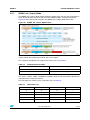
iNEMO_Set_Sensor_Parameter
The iNEMO_Set_Sensor_Parameter command allows setting a specific sensor parameter.
Figure 20 shows the frames involved in the iNEMO_Set_Sensor_Parameter transaction.
Figure 20. iNEMO_Set_Sensor_Parameter frames
Table 7 lists the type of sensor and value for the "Sensor_Type" field.
Doc ID 18128 Rev 1
21/37
STEVAL-MKI062V2 frames
2.4.2
UM1017
iNEMO_Get_Sensor_Parameter
The iNEMO_Get_Sensor_Parameter command allows retrieving a specific sensor
parameter from iNEMO . Figure 21 shows the frames involved in the iNEMO_
Get_Sensor_Parameter transaction.
Figure 21. iNEMO_Get_Sensor_Parameter frames
Table 7 lists the type of sensor and value for the "Sensor_Type" field.
2.4.3
iNEMO_Restore_Default_Parameter
The iNEMO_Restore_Default_Parameter command allows restoring a specific default
sensor parameter. Figure 22 shows the frames involved in the
iNEMO_Restore_Default_Parameter transaction.
Figure 22. iNEMO_Restore_Default_Parameter frames
22/37
Doc ID 18128 Rev 1
UM1017
STEVAL-MKI062V2 frames
Table 7 lists the type of sensor and value for the "Sensor_Type" field.
Table 7.
2.4.4
Sensor_Type field
Sensor_Type field
Sensor
0x00
3-axis accelerometer
0x01
3-axis magnetometer
0x02
2-axis gyroscope (pitch/roll)
0x03
1-axis gyroscope (Yaw)
0x04
Pressure
0x05
Temperature
0x06 – 0xFF
Reserved for future use
Accelerometer “Sensor_Parameter” field
Table 8 lists the parameters of the accelerometer and the values of the “Sensor_Parameter”
field.
Table 8.
2.4.5
Accelerometer Sensor_Parameter field
Sensor_Parameter field
Parameter
0x00
Output data rate
0x01
Full scale
0x02
Acc_HPF
0x03
Offset_X
0x04
Offset_Y
0x05
Offset_Z
0x06 – 0xFF
Reserved for future use
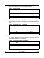
Accelerometer output data rate
The "Parameter_Value" field for the output data rate setting is 1 byte in length. Table 9 lists
the supported output data rate for the accelerometer.
Table 9.
Accelerometer output data rate and fields
“Parameter_Value” field for accelerometer
ODR
Output data rate (Hz)
0x00
50
0x01
100
0x02
400
0x03
1000
0x04 – 0xFF
RFU
Doc ID 18128 Rev 1
23/37
STEVAL-MKI062V2 frames
2.4.6
UM1017
Accelerometer full scale
The "Parameter_Value" field for the full scale setting is 1 byte in length. Table 10 lists the
supported full scale for the accelerometer.
Table 10.
2.4.7
Accelerometer full scale and fields
“Parameter_Value” field for accelerometer FS
Full scale (g)
0x00
±2 g
0x01
±4 g
0x03
±8 g
0x02, 0x04 – 0xFF
RFU
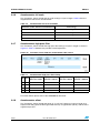
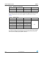
Accelerometer high-pass filter
The "Parameter_Value" field for the high-pass filter setting is 2 bytes in length as shown in
Figure 23. Table 11 indicates the possible cut-off frequencies.
Figure 23. Parameter_Value fields for accelerometer HPF setting
Table 11.
HP1 HP0
Accelerometer high-pass filter setting
ft[HZ] ODR = 00
ft[HZ] ODR = 01
ft[HZ] ODR = 10
ft[HZ] ODR = 11
data rate = 50 Hz
data rate = 100 Hz
data rate = 400 Hz
Data rate = 1000 Hz
0
0
1
2
8
20
0
1
0.5
1
4
10
1
0
0.25
0.5
2
5
1
1
0.125
0.25
1
2.5
For further details please refer to the LSM303DLH datasheet.
2.4.8
Accelerometer offset
The "Parameter_Value" field for the offset (X, Y or Z axis) setting is 2 bytes in length and
expressed in milli-g (thousandth of gravitational force) as signed short (16-bit), with the most
significant byte first.
24/37
Doc ID 18128 Rev 1
UM1017
2.4.9
STEVAL-MKI062V2 frames
Magnetometer "Sensor_Parameter" field
Table 12 lists the values and parameters of the magnetometer "Sensor_Parameter" field.
Table 12.
2.4.10
Magnetometer Sensor_Parameter field
Sensor_Parameter field
Parameter
0x00
Output data rate
0x01
Full scale
0x02
Operating mode
0x03
Offset_X
0x04
Offset_Y
0x05
Offset_Z
0x06 – 0xFF
RFU
Magnetometer output data rate
The "Parameter_Value" field for the output data rate setting is 1 byte in length. Table 13 lists
the values and the supported output data rate for the magnetometer.
Table 13.
2.4.11
Magnetometer output data rate field
“Parameter_Value” field for magnetometer
ODR
Output data rate (Hz)
0x00
0.75
0x01
1.5
0x02
3
0x03
7.5
0x04
15
0x05
30
0x06
75
0x07 – 0xFF
RFU
Magnetometer full scale
The "Parameter_Value" field for the full scale setting is 1 byte in length. Table 14 lists the
values and the supported full scale for the magnetometer.
Table 14.
Magnetometer full scale field
“Parameter_Value” field for magnetometer FS
Full scale (Gauss)
0x01
±1.3
0x02
±1.9
0x03
±2.5
Doc ID 18128 Rev 1
25/37
STEVAL-MKI062V2 frames
Table 14.
2.4.12
UM1017
Magnetometer full scale field (continued)
“Parameter_Value” field for magnetometer FS
Full scale (Gauss)
0x04
±4.0
0x05
±4.7
0x06
±5.6
0x07
±8.1
0x00, 0x08 – 0xFF
RFU
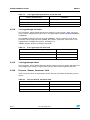
Magnetometer operating mode
The "Parameter_Value" field for the operating mode setting is 1 byte in length as shown in
Figure 24. Table 15 lists the possible magnetometer operating modes.
Figure 24. Parameter_Value fields for magnetometer operating mode setting
Table 15.
Magnetometer operating mode setting
Mode1
Mode0
Magnetic sensor operating mode
0
0
Normal
0
1
Positive bias
1
0
Negative bias
1
1
Forbidden
For further details please refer to the LSM303DLH datasheet.
2.4.13
Magnetometer offset
The "Parameter_Value" field for the offset (X, Y or Z axis) setting is 2 bytes in length and
expressed in milli-Gauss (thousandth of Gauss) as signed short (16-bit), with the most
significant byte first.
2.4.14
2-axis gyroscope "Sensor_Parameter" field
Table 16 lists the values and parameters for the "Sensor_Parameter" field for the 2-axis
gyroscope (pitch/roll) sensor.
26/37
Doc ID 18128 Rev 1
UM1017
STEVAL-MKI062V2 frames
Table 16.
2.4.15
2-axis gyroscope (pitch/roll) Sensor_Parameter field
Sensor_Parameter field
Parameter
0x00
Full scale
0x01
Offset X
0x02
Offset Y
0x03 – 0xFF
RFU
2-axis gyroscope full scale
The "Parameter_Value" field for the full scale setting is 1 byte in length. Table 17 describes
the supported full-scale for the 2-axis gyroscope available in the STEVAL-MKI062V2
(LPR430AL).
The full scale of the LPR430AL can be modified only in the hardware by changing the
position of the R77 and R78 resistors of iNEMO V2 (for further details please refer to the
related user manual UM0937). If the user changes the full scale of the LPR430AL, it also
modifies the firmware library, changing the "Gyro_Sensitivity_x", "Gyro_SensitivityLSB_x"
and "Gyro_FS_x" defined in the LPRYxxxAL.h file, where x should be P or R. For this
reason the "Full_Scale" parameter can be used only in the
"iNEMO_Get_Sensor_Parameter" command. It is not supported in the
"iNEMO_Set_Sensor_Parameter" and "iNEMO_Restore_Default_Parameter" commands
Table 17.
2.4.16
2-axis gyroscope full scale field
“Parameter_Value” field for 2-axis gyroscope (pitch/roll) FS
Full scale (dps)
0x00 – 0x03
RFU
0x04
±300
0x05 – 0x07
RFU
0x08
±1200
0x09 – 0xFF
RFU
2-axis gyroscope offset
The "Parameter_Value" field for the offset (X or Y axis) setting is 2 bytes in length and
expressed in dps (degree per second) as signed short (16-bit), with the most significant byte
first.
2.4.17
1-axis gyroscope "Sensor_Parameter" field
Table 18 lists the values and parameters for the "Sensor_Parameter" field for the 1-axis
gyroscope (Yaw) sensor.
Doc ID 18128 Rev 1
27/37
STEVAL-MKI062V2 frames
Table 18.
2.4.18
UM1017
1-axis gyroscope (yaw) Sensor_Parameter field
Sensor_Parameter field
Parameter
0x00
Full scale
0x01
Offset Z
0x02 – 0xFF
RFU
1-axis gyroscope full scale
The "Parameter_Value" field for the full-scale setting is 1 byte in length. Table 19 lists the
values and the supported full scale for the 1-axis gyroscope available in STEVAL-MKI062V2
(LY330ALH).
The LY330ALH supports only one full scale (±300 dps). For this reason the "Full_Scale"
parameter can be used only in the "iNEMO_Get_Sensor_Parameter" command. It is not
supported in the "iNEMO_Set_Sensor_Parameter" nor
"iNEMO_Restore_Default_Parameter" commands.
Table 19.
2.4.19
2-axis gyroscope full-scale field
“Parameter_Value” field for 1-axis gyroscope (yaw) FS
Full scale (dps)
0x00 – 0x03
Forbidden - RFU
0x04
±300
0x05 – 0xFF
Forbidden - RFU
1-axis gyroscope offset
The "Parameter_Value" field for the offset (Z-axis) setting is 2 bytes in length and expressed
in dps (degree per second) as signed short (16-bit), with the most significant byte first.
2.4.20
Pressure "Sensor_Parameter" field
Table 20 lists the values and parameters for the "Sensor_Parameter" field for the pressure
sensor.
Table 20.
28/37
Pressure Sensor_Parameter field
Sensor_Parameter field
Parameter
0x00
Output data rate
0x01
Offset
0x02 – 0xFF
Forbidden - RFU
Doc ID 18128 Rev 1
UM1017
2.4.21
STEVAL-MKI062V2 frames
Pressure sensor output data rate
The "Parameter_Value" field for the output data rate setting is 1 byte in length. Table 21 lists
the values and the supported output data rate for the pressure sensor.
Table 21.
2.4.22
Pressure sensor output data rate field
“Parameter_Value” field for pressure sensor ODR
Output data rate (Hz)
0x01
7
0x03
12.5
0x00, 0x02, 0x04 – 0xFF
Forbidden - RFU
Pressure sensor offset
The "Parameter_Value" field for the offset setting is 2 bytes in length and expressed in
dmbar (tenth of millibar) as signed short (16-bit), with the most significant byte first.
2.4.23
Temperature "Sensor_Parameter" field
Table 22 lists the values and parameters for the "Sensor_Parameter" field for the
temperature sensor.
Table 22.
2.4.24
Temperature Sensor_Parameter field
Sensor_Parameter field
Parameter
0x00
Offset
0x01 – 0xFF
RFU
Temperature sensor offset
The "Parameter_Value" field for the offset setting is 2 bytes in length and expressed in dºC
(tenth of a degree Celsius) as signed short (16-bit), with the most significant byte first.
Doc ID 18128 Rev 1
29/37
STEVAL-MKI062V2 frames
2.5
UM1017
Acquisition sensor data frames
Acquisition sensor data frames can be:
●
frames originated by the PC software (SDK or GUI) to set how to retrieve sensor data
from iNEMO
●
frames originated by iNEMO to send sensor data
Acquisition sensor data frames are listed in Table 23.
Table 23.
Acquisition sensor data frames
Commands
iNEMO_Set_
Output_Mode
iNEMO_Set_
Output_Mode
_Response
iNEMO_Get_
Output_Mode
iNEMO_Get_
Output_Mode
_Response
Frame type
Ack
required
Message ID
QoS
Payload
length (in
bytes)
Payload
Originator
Sensors,
acquisition
frequency, output
type, number of
samples
PC
CONTROL
Y
0x50
N
4
ACK
N
0x50
N
0
NACK
N
0x50
N
1
CONTROL
Y
0x51
N
0
iNEMO
ACK
N
0x51
N
4
Error code
PC
Sensors,
acquisition
frequency, output
type, number of
samples
NACK
N
0x51
N
1
CONTROL
Y
0x52
N
0
ACK
N
0x52
N
0
NACK
N
0x52
N
1
Error code
iNEMO_Acqu
isition_Data
DATA
N
0x52
N
variable
Sensor data
iNEMO_Stop
_Acquisition
CONTROL
Y
0x53
N
0
ACK
N
0x53
N
0
NACK
N
0x53
N
1
iNEMO_Start
_Acquisition
iNEMO_Start
_Acquisition_
Response
iNEMO_Stop
_Acquisition_
Response
30/37
iNEMO
Error code
PC
iNEMO
PC
iNEMO
Doc ID 18128 Rev 1
Error code
UM1017
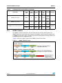
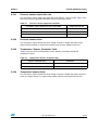
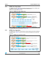
2.5.1
STEVAL-MKI062V2 frames
iNEMO_Set_Output_Mode
The iNEMO_Set_Output_Mode command allows setting which sensors shall be enabled, in
which format the data sensor shall be sent from iNEMO to SDK, and other parameters.
Figure 25 shows the frames involved in the iNEMO_Set_Output_Mode transaction.
Figure 25. iNEMO_Set_Output_Mode frames
When the "AHRS" bit is set to "1", iNEMO runs the AHRS algorithm, and in the data frame it
sends "AHRS" data (quaternion and roll, pitch, yaw angles).
The "Cal/Raw" field defines the output of the sensor data, see Table 24.
Table 24.
Calibrated and raw fields
Cal/raw field
Output data type
0
Calibrated data
1
Raw data [LSB]
The "ACC", "GYRO", "MAG", "PRESS" and "TEMP" fields are used to enable or disable the
acquisition of the respective sensors.
The FQx fields are used to set the acquisition rate, seeTable 25.
Table 25.
Acquisition rate
FQ2
FQ1
FQ0
Acquisition rate (Hz)
0
0
0
1
0
0
1
10
0
1
0
25
0
1
1
50
1
0
0
30
Doc ID 18128 Rev 1
31/37
STEVAL-MKI062V2 frames
Table 25.
UM1017
Acquisition rate (continued)
FQ2
FQ1
FQ0
Acquisition rate (Hz)
1
0
1
100
1
1
0
400
1
1
1
RFU
The OTx fields are used to set the interface through which iNEMO sends the data. The only
interface supported by the actual version of iNEMO is the USB interface, as shown in
Table 26.
Table 26.
Output interface
OT2
OT1
OT0
Output interface
0
0
0
USB
0
0
1
0
1
0
0
1
1
1
0
0
1
0
1
1
1
0
1
1
1
RFU
The "Number of Samples" bytes specify how many sensor data samples shall be acquired.
When set to zero (continuous mode), iNEMO acquires and sends sensor data to the PC
until it receives the "iNEMO_Stop_Acquisition" command.
32/37
Doc ID 18128 Rev 1
UM1017
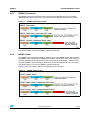
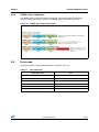
2.5.2
STEVAL-MKI062V2 frames
iNEMO_Get_Output_Mode
The iNEMO_Get_Output_Mode command allows retrieving information from iNEMO about
its acquisition settings. Figure 26 shows the frames involved in the
iNEMO_Get_Output_Mode transaction.
Figure 26. iNEMO_Get_Output_Mode frames
The "Output Mode" fields are described in Section 2.5.1.
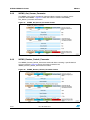
2.5.3
iNEMO_Start_Acquisition
The iNEMO_Start_Acquisition command allows starting to acquire sensor data according to
the output settings. Figure 27 shows the frames involved in the iNEMO_Start_Acquisition
transaction.
Figure 27. iNEMO_Start_Acquisition frames
Doc ID 18128 Rev 1
33/37
STEVAL-MKI062V2 frames
UM1017
The "Frame Counter" field is an unsigned short incremented every time new data is sent to
the PC.
"ACC(X,Y,Z)" represents the accelerometer data field. This data field is available only if the
accelerometer sensor has been enabled ("ACC" field in "iNEMO_Set_Output_Mode" frame
is 1). If the "Raw" option is not enabled ("Raw" field in "iNEMO_Set_Output_Mode" frame is
0), each accelerometer axis value is expressed in mg (thousandth of gravitational force) in
one of the possible ranges defined in Table 10, as a signed short value (2 bytes). If the
"Raw" option is enabled, each axis value represents the raw sensor data (LSB value).
"GYRO(X,Y,Z)" represents the gyroscope data field. This data field is available only if the
gyroscope sensor has been enabled ("GYRO" field in "iNEMO_Set_Output_Mode" frame is
1). If the "Raw" option is not enabled, each gyroscope axis value is expressed in dps
(degrees per second) in one of the possible ranges defined in Table 17 and Table 19, as a
signed short value (2 bytes). If the "Raw" option is enabled, each axis represents the raw
sensor data (LSB value).
"MAG(X,Y,Z)" represents the magnetometer data field. This data field is available only if the
magnetometer sensor has been enabled ('MAG" field in "iNEMO_Set_Output_Mode" frame
is 1). If the "Raw" option is not enabled, each magnetometer axis value is expressed in mG
(thousandth of Gauss) in one of the possible ranges defined in Table 14, as a signed short
value (2 bytes). If the "Raw" option is enabled each axis value represents the raw sensor
data (LSB value).
"PRESS" represents the pressure data field. This data field is available only if the pressure
sensor has been enabled ("PRESS" field in "iNEMO_Set_Output_Mode" frame is 1). If the
"Raw" option is not enabled, the pressure value is expressed in d-mbar (tenth of millibar) in
the range [+3000 d-mbar to +11000 dmbar], as unsigned short value (2 bytes). If the "Raw"
option is enabled, the pressure data field represents the raw sensor data (LSB value).
"TEMP" represents the temperature data field. This data field is available only if the
temperature sensor has been enabled ("TEMP" field in "iNEMO_Set_Output_Mode" frame
is 1). If the "Raw" option is not enabled, the temperature value is expressed in dºC (tenth of
a degree Celsius) in the range [-550 dºC, + 1250 dºC], as a signed short value (2 bytes). If
the "Raw" option is enabled, the temperature data field represents the raw sensor data (LSB
value).
"RPY" represents the roll, pitch, yaw data field. This data field is available only if the "AHRS"
option has been enabled ("AHRS" field in "iNEMO_Set_Output_Mode" frame is 1).
The Roll data is expressed as a floating point value (4 bytes) in the range ±180 degrees.
The Pitch data is expressed as a floating point value (4 bytes) in the range ±90 degrees.
The Yaw data is expressed as a floating point value (4 bytes) in the range ±180 degrees.
"Quaternion" represents the quaternion data field. This data field is available only if the
"AHRS" option has been enabled ("AHRS" field in "iNEMO_Set_Output_Mode" frame is 1).
Each quaternion data is expressed as a floating point value (4 bytes) in the range ±1. The
Q0 field represents the scalar part of the quaternion, while the Q1, Q2 and Q3 field
represent the vector part of the quaternion.
During the acquisition and data transmission phase it is not possible to use commands that
change the sensor settings or the output mode. The acquisition phase must be stopped
before sending these commands.
34/37
Doc ID 18128 Rev 1
UM1017
2.5.4
STEVAL-MKI062V2 frames
iNEMO_Stop_Acquisition
The iNEMO_Stop_Acquisition command stops the acquisition and data transmission.
Figure 28 shows the frames involved in the iNEMO_Stop_Acquisition transaction.
Figure 28. iNEMO_Stop_Acquisition frames
2.6
Error code
All the error codes used in the NACK frames are listed in Table 27.
Table 27.
Error code field
“Error Code” field
Error
0x01
Unsupported command
0x02
Value out of range
0x03
Not executable command
0x04
Wrong syntax
0x05
iNEMO not connected
0x06 – 0xFF
RFU
Doc ID 18128 Rev 1
35/37
Revision history
3
UM1017
Revision history
Table 28.
36/37
Document revision history
Date
Revision
23-Feb-2011
1
Changes
Initial release.
Doc ID 18128 Rev 1
UM1017
Please Read Carefully:
Information in this document is provided solely in connection with ST products. STMicroelectronics NV and its subsidiaries (“ST”) reserve the
right to make changes, corrections, modifications or improvements, to this document, and the products and services described herein at any
time, without notice.
All ST products are sold pursuant to ST’s terms and conditions of sale.
Purchasers are solely responsible for the choice, selection and use of the ST products and services described herein, and ST assumes no
liability whatsoever relating to the choice, selection or use of the ST products and services described herein.
No license, express or implied, by estoppel or otherwise, to any intellectual property rights is granted under this document. If any part of this
document refers to any third party products or services it shall not be deemed a license grant by ST for the use of such third party products
or services, or any intellectual property contained therein or considered as a warranty covering the use in any manner whatsoever of such
third party products or services or any intellectual property contained therein.
UNLESS OTHERWISE SET FORTH IN ST’S TERMS AND CONDITIONS OF SALE ST DISCLAIMS ANY EXPRESS OR IMPLIED
WARRANTY WITH RESPECT TO THE USE AND/OR SALE OF ST PRODUCTS INCLUDING WITHOUT LIMITATION IMPLIED
WARRANTIES OF MERCHANTABILITY, FITNESS FOR A PARTICULAR PURPOSE (AND THEIR EQUIVALENTS UNDER THE LAWS
OF ANY JURISDICTION), OR INFRINGEMENT OF ANY PATENT, COPYRIGHT OR OTHER INTELLECTUAL PROPERTY RIGHT.
UNLESS EXPRESSLY APPROVED IN WRITING BY AN AUTHORIZED ST REPRESENTATIVE, ST PRODUCTS ARE NOT
RECOMMENDED, AUTHORIZED OR WARRANTED FOR USE IN MILITARY, AIR CRAFT, SPACE, LIFE SAVING, OR LIFE SUSTAINING
APPLICATIONS, NOR IN PRODUCTS OR SYSTEMS WHERE FAILURE OR MALFUNCTION MAY RESULT IN PERSONAL INJURY,
DEATH, OR SEVERE PROPERTY OR ENVIRONMENTAL DAMAGE. ST PRODUCTS WHICH ARE NOT SPECIFIED AS "AUTOMOTIVE
GRADE" MAY ONLY BE USED IN AUTOMOTIVE APPLICATIONS AT USER’S OWN RISK.
Resale of ST products with provisions different from the statements and/or technical features set forth in this document shall immediately void
any warranty granted by ST for the ST product or service described herein and shall not create or extend in any manner whatsoever, any
liability of ST.
ST and the ST logo are trademarks or registered trademarks of ST in various countries.
Information in this document supersedes and replaces all information previously supplied.
The ST logo is a registered trademark of STMicroelectronics. All other names are the property of their respective owners.
© 2011 STMicroelectronics - All rights reserved
STMicroelectronics group of companies
Australia - Belgium - Brazil - Canada - China - Czech Republic - Finland - France - Germany - Hong Kong - India - Israel - Italy - Japan Malaysia - Malta - Morocco - Philippines - Singapore - Spain - Sweden - Switzerland - United Kingdom - United States of America
www.st.com
Doc ID 18128 Rev 1
37/37