1
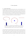
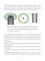
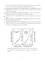
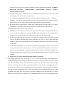
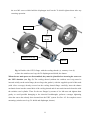
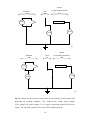
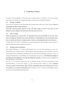
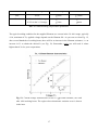
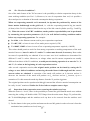
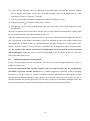
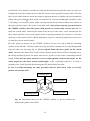
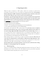
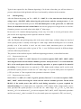
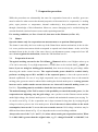
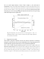
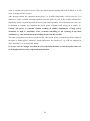
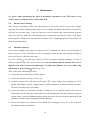
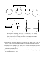
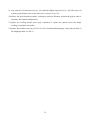
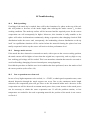
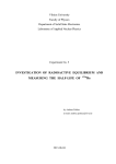
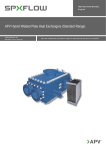
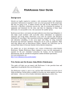
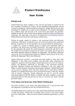
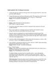
TriCon electron bombardment evaporation source
User’s manual
(version 3.1/May 9, 2000)
Dr. R. Verucchi
INFM, UdR of Modena
Read the Manual carefully!
This manual replaces any previous version!
The TriCon evaporation source is not an “ordinary” device, even if based
on well known physical principles: its use without a careful reading of this
manual will damage seriously both the source and the power supplies.
Take the time to read the manual, in order to understand what is different
and “how-it-works”.
Operations with the TriCon source are not “more difficult” than in usual
sources, they are simply “different”. So, please read carefully the manual
and spend some minutes to verify how the new triode electrodes
configuration has been realized making an inspection of the evaporation
zone: this will help you to understand why some precautions are necessary
and how high performances can be achieved.
The triode electrodes configuration applied
in an evaporation source based on electron
bombardment is protected by the italian
patent n. GE98 A 000096, deposited on
November 1998, 18th by INFM and R.
Verucchi.
ii
Table of contents.
1.
Theory of operation. .................................................................................................................. 2
1.1. The new TriCon concept. ........................................................................................................ 2
1.2. Performances........................................................................................................................... 5
Source description .............................................................................................................................. 7
3.
Installation. .............................................................................................................................. 12
3.1. Source-substrate distance and beam divergence. .................................................................. 13
3.2. Electrical connections. .......................................................................................................... 15
4.
Common procedures ............................................................................................................... 16
4.1. Starting conditions. ............................................................................................................... 16
4.2. Water cooling. ....................................................................................................................... 16
4.3. Turning on the hot filament. ................................................................................................. 16
4.4. “Z0 - Zero level conditions”. ................................................................................................. 18
4.5. Inspection of the evaporation zone: removing the stainless steel cap................................... 18
4.6. Evaporating material cooling down. ..................................................................................... 19
5.
Evaporating material mounting. ............................................................................................ 20
5.1. Rod. ....................................................................................................................................... 20
5.2. Crucible. ................................................................................................................................ 21
5.3. Anode positioning and centering. ......................................................................................... 21
6.
Degassing procedure. .............................................................................................................. 23
6.1. Filament degassing................................................................................................................ 23
6.2. Grid degassing....................................................................................................................... 24
6.3. Anode degassing. .................................................................................................................. 24
6.3.1.Evaporation from rod ....................................................................................................... 24
6.3.2.Evaporation from crucible. ............................................................................................... 24
6.4. Internal walls degassing. ....................................................................................................... 25
6.4.1.Evaporation from rod. ...................................................................................................... 25
6.4.2.Evaporation from crucible. ............................................................................................... 25
7.
Evaporation procedure. .......................................................................................................... 26
7.1. Shutter ................................................................................................................................... 26
7.2. Evaporation from rod. ........................................................................................................... 26
iii
7.3. Evaporation from crucible. ................................................................................................... 27
8.
Some practical suggestions. .................................................................................................... 29
9.
Maintenance. ............................................................................................................................ 30
9.1. Internal parts cleaning. .......................................................................................................... 30
9.2. Filament replacing................................................................................................................. 30
10. Troubleshooting. ...................................................................................................................... 33
10.1. Rod tip melting. .................................................................................................................... 33
10.2. Strange anode current............................................................................................................ 33
10.3. Low evaporation rates from rod. ........................................................................................... 33
iv
Symbol legend.
HV = High Voltage
VF = hot filament voltage
IF = hot filament current
VG = grid voltage
IG = grid current
VA = anode (evaporating material) voltage
IA = anode (evaporating material) current
UHV = Ultra High Vacuum
R = evaporating point-substrate distance
1
1. Theory of operation.
1.1.
The new TriCon concept.
The evaporation in UHV of material (mainly metals) by means of electron bombardment is a well
established technique. The main scheme of such a source is that of a vacuum diode (see Fig. 1):
electrons are emitted from a hot filament (cathode) by thermionic effect and are accelerated towards
a higher potential electrode (anode). The energy transfer by electron bombardment on the anode can
lead to very high surface temperature, up to 3000K: if the material has very high vapor pressure (at
least 10-4, 10-3 Torr) before the melting point, it is possible to maintain the evaporating material in
the solid state and obtain good evaporation rates from a relatively simple device.
a)
b)
c)
Fig. 1: Scheme for a conventional electron bombardment source, substantially a
vacuum diode: hot filament (the cathode, red) and the evaporating material (in
form of rod, the anode, blue) are shown. a) 3D view; b) top view; c) lateral view.
The main disadvantage is the strong limitation of the anode current due to space charge effect: very
high anode voltages (>2000V), short distances between filament and anode, high thermionic
emission (filament temperature >2400K) can only partially overcome the problem. Moreover, due
to the continuos material consumption, the anode-filament distance progressively increases, thus
producing a reduction of the anode current: this requires a continuos increase of the anode voltage
2
or/and of the hot filament temperature, until a repositioning of the anode is absolutely necessary
(e.g., by means of a linear motion feedthrough). It is difficult to obtain a reproducible working
condition; however, an “active” closed loop control on the evaporation rate (acting on the filament
temperature or anode voltage) is possible by a direct measure of the evaporated material flux.
a)a)
b)
c)
Fig. 2: Scheme for the TriCon electrodes configuration: the presence of the grid
(green) between cathode (red) and anode (blue) shows the “triode” structure of the
source. The gray cylinder around the blue anode is set at ground potential. a) 3D
view; b) top view; c) lateral view.
The TriCon source has a different electrodes structure: it is the configuration of a “triode” (Italian
Patent pending n. GE98 A 000096, November 18th 1998). As shown in Fig. 2, the anode is
surrounded by a metal tube set at ground potential and the electron emitting filament is positioned
around it. A grid, set at a positive potential, is located between the filament and the anode, on the
top tube edge.
The main advantages are:
absence of space charge current limitations due to the high electrical field created by the grid in
the filament region;
high anode current even at low filament temperature (2200-2300K) and low anode voltage
(600-1200V);
high electrical field uniformity inside the source, good electrons distribution on the anode
surface;
“fine tuning” of the anode current: once the filament power (i.e., temperature) and the anode
voltage are set, the anode current/power is regulated by variations of the positive grid voltage.
3
The precision is higher than in conventional electron bombardment sources, with the possibility
to work very close to the material melting point, with higher evaporation rates;
the anode current reduction due to its length reduction is counterbalanced by a grid
voltage increase: it is possible to work with the same evaporating condition up to a reduction of
1.5-2mm of the anode length;
anode power stability means evaporating rate stability: it is possible to maintain this last
constant just by variation of the grid voltage, without changing anything else;
the anode length can be easily monitored when the source is “in-situ”, with a precision of
0.2mm;
superior reliability and reproducibility of the performances, higher and “easier-to-obtain”
than in the conventional “diode” sources;
evaporation from crucible: it acts as a real Knudsen cell, material evaporation is obtained by
crucible walls heating due to electron bombardment of its external surfaces. Evaporation from
semiconductors and insulating material too can be obtained.
Fig. 3: Evaporation rates (source-substrate distance of 10cm) vs. anode power for:
a) 1 mm
Fe rod, 1000V anode voltage; a) 2 mm
voltage.
4
V rod, 1200V anode
An additional power supply, 250V/50mA, is necessary with respect to the diode-like sources. The
power dissipated by the grid is usually low (<4W), even at the higher voltages: so, degassing and
heat irradiation from the grid can be disregarded.
The TriCon concept has been inserted into a complete source designing, shown and described
hereafter. The whole project has been developed and supported in 1997-1998 by INFM, Istituto
Nazionale di Fisica della Materia, at the Physics Department of the University of Modena, Italy.
Fig. 4: Evaporation rates (source-substrate distance of 10cm) vs. anode power for
crucible filled with: a) Si; b) Ge.
1.2.
Performances.
Evaporation have been obtained from several materials, as shown in Tab. 1. Evaporation rates
depends on the material thermal properties and on the source-substrate distance: data shown in Fig.
3 are for a 1mm
Iron rod (a) and a 2mm
Vanadium rod (b). Rods of different diameter will
show very different performances. For what concern the role of the distance R, the well known 1/R 2
flux dependence on the distance have to be taken into account.
It is very difficult to connect the anode power to the material temperature: in the Tab. 1, some
indicative data are shown for both evaporation from rod and crucible. However, the shape, the
5
dimensions of the rod or rock-like crystal used are fundamental in determining the anode power for
the required temperature, i.e. vapor pressure.
Material
Notes
Evaporation from rod
Evaporation from crucible
( 2mm)
Anode power Temperature Crucible power
Ag
B
large, irregular rock-
12W
1700-1900 C
12W
1500 C
Temperature
15W
1100-1200 C
13W
1000 C
20W
1300-1400 C
4W
300 C
60W
1700 C
like crystal
Co
Rod
2mm
Cu
Fe
Ge
Rod
1mm
5.5W
1500-1600 C
Rod
2mm
12W
1500-1600 C
7W
1000 C
40W
2700 C
Large, irregular rocklike crystal
Mo
PcCu
Rod
1.5mm
Powder, copper
phthalocyanine
Ni
Si
Rod
2mm
Large, irregular rock-
12W
1500 C
9W
1400 C
30W
2400-2600 C
like crystal; wafer
Ta
Rod
2mm; 0.2mm
thin foil, 3mm wide
V
Rod
2mm
21W
1900 C
W
Rod
2mm
45W
2700-3000 C
Tab. 1: Temperature vs. anode power for several elements, for evaporation from rod or
crucible.
6
2. Source description
Air side
a)
UHV side
b)
Fig. 5: The TriCon source: air side (a) and (b) vacuum side are put in evidence.
7
b)
a)
Fig. 6: The TriCon source, with the two parts not assembled: the CF35 main
flange (a) and the CF35 double sided flange with the cooling shroud (b).
Shutter
motion
feedthrough
Not used
Not used
Filament
Grid
Filament
CF35 flange
Fig. 7 Sketch of the rear view (source air side view) to show the pins for electrical
connections on the main CF35 flange. The HV anode feedthrough is mounted on a
CF16 flange at the bottom of the linear motion feedthrough (not shown here).
8
MACOR cylinder
Stainless steel
connectors
Mo central tube
a)
VESPEL
cylinder
Filament (red)
Ta shield
Anode (yellow)
Mo electrodes
Grid (green)
b)
Fig. 8: UVH side of the main CF35 flange assembly (a), with an expanded view
of the electrodes zone (b).
The source is composed of two parts (Fig. 6), i.e. two CF35 flange assemblies that must be mounted
together by means of special studs:
1) the motion and electrical feedthrough CF35 flange (the main flange, see Fig. 5a). On the air side
it is composed of (see also Fig. 6a):
a) the 5cm UHV linear movement (located on the main source axis, with an edge welded
bellow and a millimetric scale located on a stainless steel plate): the movement is obtained
9
by means of a M6 screw on which is mounted a M8 hexagonal nut. Remember: 1 complete
turn=1mm
movement,
counterclockwise
rotation=anode
insertion,
clockwise
rotation=anode extraction .;
b) the High Voltage (HV) feedthrough on a CF16 flange (located at the source bottom on the
CF16 flange of the linear motion mechanism);
c) five electrical feedthroughs (3000V/5A) welded on the CF35 flange (see Fig. 7): Filament +,
Filament -, Grid, and two not used. The electrical connections (one MHV connector and a 6
pins-connector) for the power supply are positioned on the stainless steel plate.
d) the linear motion for the shutter: a small edge welded bellows located on the CF35 flange,
connected by a mechanical arm with the on/off lever on the bottom source air side.
In the UHV side are present (see Fig. 5b, Fig. 8):
e) a Molibdenum (Mo) tube O.D. 10mm, I.D. 8mm, with a Tantalum (Ta) shield inserted on its
top; the anode (a stainless steel cylinder 4mm , 12cm long with the Mo material holder
screwed on it) is inside the Mo tube and screwed on the main HV feedthrough.
f) On the basis of the Mo tube (near the CF35 flange) are located a brown VESPEL ceramic
cylinder for anode centering and correct positioning (see Par5.3), and a white MACOR
ceramic cylinder, to hold and grant electrical insulation among the 5 pins coming from the
CF35 flange.
c) On the MACOR cylinder are located the two filament and the grid electrodes. Each of them
is composed of a stainless steel connector, inserted into the MACOR cylinder and on the rod
of an electrical feedthrough (contact is granted by a M2 grain), and of a Mo 3mm
with a
M2 hole on the top. By means of M2 screws, the filament and the grid are fixed on the Mo
cylinders.
d) The grid is a Ta woven mesh, not welded: handle it carefully!
2) The cooling shroud (see Fig. 6b and Fig. 9): it is a 316LN stainless steel tube connected to a
double-sided tapped CF35 flange by means of two tubes, entirely located on the UHV source
side. The CF35 flange on the vacuum side will be connected to the CF35 main chamber flange.
The tube is closed, at the top side, by a hollowed stainless steel cap (hole, 6mm
); this is also
the support for a Ta shield and a diaphragm, for the beam monitor electrodes and for the shutter.
The tube has three longitudinal holes to allow the presence of the shutter mechanical arm (1mm
stainless steel bent rod) and of the two electrical contacts for the beam monitor. 6 special
studs are screwed on the CF35 flange. The Ta diaphragm can be set in the correct position using
10
the two M2 screws which hold the diaphragm itself on the Ta shield: tighten them after any
centering operation.
a)
Ta shield
Cooling
shroud
Ta diaphragm
b)
Stainless steel cap
Shutter
Fig. 9: Double sided CF35 flange with the cooling shroud (a); cutaway view (b)
to show the stainless steel cap, the Ta diaphragm and shield, the shutter.
When the two main parts are disassembled, they must be joined before inserting the source on
the UHV chamber (see Fig. 5). The cooling shroud (without the stainless steel cap) must be
inserted axially on the main flange (do not forget the gasket!), with the supplied special 6 M6 studs
(with silver coverage) already screwed on the cooling shroud flange: carefully, insert the shutter
mechanical arm into the central hole of the cooling shroud and do not touch internal electrodes with
the stainless steel cylinder. Then fix the two flanges by means of six M6 nuts and tighten them
gently: to avoid possible damaging to the electrical feedthroughs, perform a stronger tightening
when the source has already been inserted into the UHV system. See Par. 4.5 for complete source
mounting (stainless steel cap, Ta shield and diaphragm, shutter).
11
3. Installation.
The source mounting on a UHV system requires the presence of a CF35 flange, with not
threaded holes and standard internal diameter requirements: use M6 nuts, do not use M6
plates. Depending on the evaporation material type and form, care must be taken in positioning the
source, e.g. vertical or off-vertical, downward or upward facing.
Evaporation from rod
If a rod is installed in the source, the device can be mounted in every position, vertical (upward or
downward) or horizontal. In case of vertical mounting, with the source pointing downward, more
care must be taken to avoid evaporating material tip melting, with possible drop falling outside from
the source or inside it.
Evaporation from crucible
In case of the presence of a crucible, a horizontal mounting will produce a material fall out from the
source, so a minimum inclination of about 10 -20 (upward) should be used.
The source is fixed by means of six M6 nuts tightened on the supplied special studs. The six M6
nuts on the main flange grants joining of the two source parts: so, to remove the TriCon source
from the vacuum chamber, do not unscrew the nuts on the source flange air side, remove only
those on the vacuum chamber flange side.
Before inserting the source in the UHV system, and after any kind of “in air” operation on the
source, perform a careful inspection of the electrodes zone (see Fig. 10 and Par. 4.5). Moreover,
verify the grid-filament distance to be about 2mm, the distance between grid and the top
of the two filament electrodes (Mo 3mm
cylinder) to be about 1mm;
verify the grid and filament perpendicularity to the main source axis;
verify that the grid and the filament distance with respect to the Ta cylinder and shroud
internal walls is higher then 1mm;
verify the resistance between filament, grid, anode to be higher than 20M
in any case;
verify the resistance between filament and ground, grid and ground, anode and ground to
be higher than 20M
in any case;
verify filament resistance: it should be about 0.4-1 ;
verify the correct position of the Ta diaphragm.
12
Evaporating material (rod)
Grid
Ta shield
Mo electrodes
and screws
Filament
Mo tube
Fig. 10: Particular of the electrodes zone.
3.1.
Source-substrate distance and beam divergence.
To evaluate the correct distance R [mm] between the source, i.e. the real evaporating point, and the
growing substrate (or the thickness monitor) some parameters have to be known. If the distance L1
between the substrate and the top of the source (i.e. the shutter or the Ta diaphragm) is known, R =
L1+30 mm; if the distance between the UHV chamber CF35 flange and the substrate is L2, R=L2-90
mm. A typical working distance is R=100mm.
For what concern the beam divergence, it depends on the hole diameter of the Ta diaphragm: see
Tab. 2. In case of evaporation from crucible, the TriCon source inclination can lead to different
results from those reported in Tab. 2.
Ta diaphragm hole
(mm)
Beam divergence
1
0.9
2
1.9
3
2.8
4
3.8
5
4.7
6
5.7
Tab. 2: Beam divergence vs. the diameter of the Ta diaphragm hole.
13
Anode
Filament
(evaporating material)
Grid
+
VF/IF
+
+
VA/IA
VG/IG
-
-
a)
Anode
Filament
Grid
(evaporating material)
+
VF/IF
+
-
VA/IA
VG/IG
-
+
b)
Fig. 11: Sketch for the electrical connections for the normal (a) and internal wall
degassing (b) working condition: VF/IF, filament low voltage power supply;
VG/IG, grid 250V power supply; VA/IA, anode (evaporating material) HV power
supply. The “ground” symbol refers to the UHV chamber ground.
14
3.2.
Electrical connections.
In Fig. 11a are described the electrical connections between the power supply and the source
electrodes: all the power supply negative connections are referred to the chamber ground
level. The use of the TriCon power supply is strongly recommended to ensure safe and reliable
operations. In case of use of different power supplies, always respect the shown electrical
connections.
Electrical connections shown in Fig. 11a are those for normal operation and for the filament,
grid and anode degassing (grid power supply switch in NORMAL), while those shown in Fig.
11b are for the case of internal walls degassing (grid power supply switch in DEGASSING), as
described also in Par.6.4.
15
4. Common procedures
The hint of this paragraph is to describe some operations that are “common” for several working
procedures, as well as to give suggestions that are useful in most of practical situation.
4.1.
Starting conditions.
Before every operations, check connections between the source and on the power supply. Turn all
potentiometers fully counterclockwise.
The UHV system pressure must be in the 10-6 mbar range or lower: never turn on the
filament or give voltage to the electrodes when the source is in air!
4.2.
Water cooling.
Check the presence of a water flow. If evaporation has to be performed, be sure the water
flow is cooling the shroud from at least 15 minutes. If degassing has to be performed, water
has to be blown out from the cooling circuit, as well as connecting tubes have to be removed.
A water flux of 0.5 l/min is sufficient for a good cooling action: the maximum water pressure is
related to the type of water connections chosen.
4.3.
Turning on the hot filament.
The supplied filament is a 0.25mm
Tantalum wire, one coil self sustaining (see Fig. 10).
Tantalum has been chosen because of its thermionic emission properties and its ductility: it can be
easily shaped and its substantially unaffected by stress release during heating. However, in case of
strong current increases, wire bending can occur and shorts can occur: so, the following turning on
procedure must be followed, every time the filament is turned on. This will ensure long filament
life and absence of deformation.
See Fig. 11a for electrical connections. Set the filament voltage and current potentiometer fully
counterclockwise, set the grid voltage VG=+10V and the anode voltage VA=100V. Filament
current IF must be increased in step of 0.25A (maximum current increasing step is 0.33A)
every 30sec, or every 45sec if filament is new, as shown in Tab. 3. Faster step and higher current
increase will result in filament deformation.
16
Ta filament life
Current step
Time step
Total time
New
0.25A
45sec
12min
Used
0.33A in the 0÷2A range
30sec
3min
0.25A in the 2÷5A range
30sec
4min
Tab. 3: Filament turning on procedure parameters.
The typical working condition for the supplied filament are: current in the 3.8-4.4A range, typically
4.1A, maximum 4.7A, applied voltage depends on the filament life. As you can see from Fig. 12,
after several hundreds of working hours, there will be an increase in the filament resistance, i.e. an
increase in VF to obtain the desired IF (see Fig. 12). Remember: rarely you will need IF values
higher than 4.3A for your evaporations.
Fig. 12: Current-voltage characteristic for the Ta
0.25mm filament, new and
after 1000 working hours. The region where thermionic emission occur is shown
in the inset.
17
“Z0 - Zero level conditions”.
4.4.
One of the main feature of the TriCon source is the possibility to obtain evaporation always in the
same working condition (see Par.1.1). Moreover, in case of evaporation from rod, it is possible a
direct and precise evaluation of the anode consumption during evaporation.
When an evaporating material rod is mounted, its tip must be positioned by means of the
linear motion feedthrough at the grid level, i.e. with the evaporating material tip just outside
(0.5mm) of the Ta foil cylindrical shield on the top of the Mo central cylinder (see Fig. 2 and Fig.
10). When the source is in UHV conditions, anode position reproducibility can be performed
by measuring the operation parameters (IG, IA) in well defined working conditions and/or
before any evaporating operations. For example:
IF=4.10A, or the filament current used in your evaporation experiment
VG=40V, 50V, or lower in case of low anode power required (<5W)
VA=1000V, 1200V or lower in case of low evaporating temperature required (<1000K)
This values should permit to work far from strong evaporation or melting temperatures of the used
material: however, lower IF and/or VG and/or VA values must be used, if necessary. Best results
in terms of reproducibility are obtained if two or more zero level conditions are determined for
different VG and VA values. Moreover, as voltage values used in current evaporation are usually
different from those of the Z0 conditions, a useful practice during operation is to note the VG, IG
and VA, IA values at the beginning of each evaporation session.
After several evaporation session, the original anode position can be found by setting the Z0
voltage or user defined conditions and moving the anode linear feedthrough until the correct
current values are obtained. A retraction of the anode will produce an IG increase and an IA
decrease. An insertion of the anode will produce an IG decrease and an IA increase, up to a
saturation of IA: this means the anode tip distance from the Z0 position is 6mm.
The original position can be reproduced within 0.1mm and the effective material consumption can
be easily “in-situ” monitored. Define the Z0 level after a complete source degas.
4.5.
Inspection of the evaporation zone: removing the stainless steel cap.
When the source is “in air”, there is the possibility to control the grid-filament-anode zone without
removing the cooling cell double sided CF35 flange from the main source flange. To perform this,
the Ta shield/diaphragm and the stainless steel cap have to be removed from the stainless steel
shroud.
1) Put the shutter in the open position and unscrew the two M2 grains in order to loosen it from the
mechanical arm (stainless steel rod, 1mm
);
18
2) remove the two M2 nuts (they are tightened on two M2 grains with two M2 washers) holding
the Ta shield: now gently remove the Ta shield, together with the Ta diaphragm (it is not
necessary to remove it from the Ta shield);
3) remove the third M2 nut (and its washer) that holds the stainless steel cap;
4) displace the 1mm
mechanical arm from the shutter;
5) dislodge the cap from the cooling shroud (the three M2 grains will remain tightened on the
shroud itself).
Now the evaporation zone can be seen, with the grid over the filament, the internal Ta cylinder with
the evaporating material and material holder inside of it.
After the required operations, reinstate the source cap on the cooling shroud and tighten the M2 nut
(the one opposite to the shutter mechanism). Insert the mechanical arm in the proper shutter hole
and position the Ta shield on the cap, tightening the two M2 nuts. Tighten the two M2 grains on the
shutter: when the shutter is closed, it must be parallel to the Ta diaphragm and far 1mm from this
one. Be careful: if the shutter touches the Ta diaphragm, the linear motion for its movement
will be damaged! Adjust the position of the Ta diaphragm on the Ta shield, in order to center the
hole on the main source axis.
4.6.
Evaporating material cooling down.
In case of evaporation from rod, no problems will occur for every working condition if a quick or
sudden cooling occurs:.
In case of evaporation from crucible, instead, great care must be taken for the cooling down
procedure to prevent crucible cracks due to a sudden temperature reduction. If the evaporating
material is in a liquid state in a ceramic or metallic crucible, and interactions among the crucible
material and the melted substance occur, anode power must be decreased very slowly. In case of
crucible breaking, the internal part of the TriCon source could be irremediably damaged! Take also
into account that some material, after having been melted, must remain in liquid state.
19
5. Evaporating material mounting.
The source is equipped with two Mo material holder, 3cm long (see Fig. 13), respectively designed
for 1mm and 2mm diameter rod. This last is also used for crucible supporting.
To mount the evaporating material, first remove the stainless steel cap (see Par. 4.5) in order to see
the evaporation zone. Unscrew the three M3 grains for anode positioning (1 turn will be enough) to
leave the anode totally free. Then use the following procedures for rod or crucible mounting.
Mo M2 screws
Insert
material
M2 hole
here!
Fig. 13: Sketch for the Mo material holder (lateral view): the material (or the
crucible) must be inserted from the right. The left part is M2 threaded in order to
screw the device on the stainless steel cylinder.
5.1.
Rod.
With the two material holders supplied, it is possible to insert cylindrical rod with diameter in
the 0.8-3mm range. Move the anode to the uppermost position: the material holder is now at the
level of the Ta cylinder on the top of the Mo tube. Unscrew the material holder by means of flat end
pins, then extract it carefully without touching the grid and/or the filament. Never mind if the
material holder together with the 4mm
stainless steel rod are extracted (see Par.5 for more
details): this is due to the coupling among them, that is stronger than that of the rod and the HV
feedthrough.
Unfasten the two Mo M2 screws located on the material holder (see Fig. 13): they are very short, do
not unscrew them completely. If the two screws are blocked, wet the tip of the screwdriver with
some alcohol drops and gently unfasten the two screws. The rod can be inserted in the material
holder for a maximum/minimum length of 8mm/3mm: then, gently tighten the two Mo M2 screws,
alternatively, to reach a good mechanical contact among the rod and the material holder.
After material mounting, just screw the material holder on the central rod (or the whole central
stainless steel rod on the HV feedthrough).
20
It is possible to insert material inform of foils, wafers, or even with no regular shape, as rocks:
in this case, absolutely avoid contacts between the material itself and the Mo tube, whose
internal diameter is 8mm. Avoid material pieces with external dimension that are larger than 3 3
mm2 or with strong longitudinal deformations: it could be even impossible to center the anode for
the whole material length.
Minimum and maximum lengths for rod or rocks are 5mm and 55mm! Remember that the
maximum anode linear excursion is 50mm! See the scale on the metal plate, on the air side of
the TriCon source.
5.2.
Crucible.
The crucible is shaped in order to be positioned on the molybdenum 2mm
material holder.
If the used crucible has an outside diameter of 9mm or higher, the grid must be removed to
avoid shorts among the grid itself and the HV anode. However, it is strongly recommended to
always remove the grid when using the crucible: contact 2M Strumenti service for further
information. To remove the grid, first unscrew with an allen key the M2 grain which holds the
grid-molybdenum electrode-stainless steel barrel system on the electrical feedthrough; then gently
take away the whole from the white MACOR cylinder and remove it from the top of the cooling
shroud, avoiding contacts among grid and the filament. Put the grid assembly in a safe place.
Remove the tantalum cylinder inserted on the top of the molybdenum central tube: there is a tight
mechanical fitting among the two tubes, so extraction have to be done firmly. This operation is
always necessary, whatever the crucible dimensions are.
Move the linear motion feedthrough in order to put the anode in a position where extraction of the
evaporating material holder is possible, as previously described in Par.5.1; then, insert the crucible
in the material holder and tighten the two material holder screws to fix the crucible. By using the
linear motion feedthrough, put the crucible with its external lower edge +1mm over the
filament plane, i.e. ~4mm from the Mo tube edge.
The crucible can be filled with the evaporating material when it is positioned in the source or
before. Do not let fall pieces of material inside the Mo tube, otherwise electrical shorts or
mechanical damaging of the edge welded bellows of the linear motion feedthrough will occur. Do
not fill completely the crucible volume; maximum material quantity is about ¾ of the total
volume, but may be lower for materials which tends to wet the crucible walls.
5.3.
Anode positioning and centering.
An important operation with the TriCon source is to put the anode in the correct position from the
point of view of the main source axis and distance from the grid. The correct axial anode lateral
21
position have to be found to reach the best electrical field uniformity inside the source, as well as to
establish the necessary distance between the HV anode and the grounded internal walls of the Mo
tube. Do no bother about the anode movement or apparent absence of rigidity: the poor mechanical
fitting among the 4mm
central anode rod and the HV electrical feedthrough (mounted on the
CF16 flange) is necessary to allow anode centering and electrical contact without stress transfer to
the main external ceramic. The source is provided with a three-point centering system located in
the VESPEL cylinder: three M3 grains (120 spaced) are transversally screwed into and can
touch the central anode. Observing the anode from the top of the source, screw and unscrew the
three grains until the correct axial position of the evaporating material tip is found, i.e. when the
anode tip is at the center of the Ta shield. Sometimes, only two of the three grains have to be moved
to reach the correct central location.
Five M3 grains are present on the VESPEL cylinder, but two are used to hold the insulating
cylinder on the Mo tube. The three grains necessary for anode centering can be easily distinguished
from the other two observing Fig. 14. Do not tighten firmly the three grains on the central
anode, otherwise the anode itself will be blocked and the linear motion could be damaged due to
the strong mechanical strains: the anode must be free to move for the whole evaporating material
length. Verify that the anode position is correct within 0.5mm of lateral movement, for the
whole length (use the linear motion feedthrough). If the evaporating material is in form of
irregular rocks, avoid electrical shorts among the HV anode and the Mo tube.
In case of crucible mounting, the same procedure must be observed in order to correctly
position the crucible itself.
Centering grain
Holding grain
Holding grain
Centering grain
Centering grain
Fig. 14: Horizontal cutaway of the VESPEL cylinder, to put in evidence the
different M3 grains screwed into.
22
6. Degassing procedure.
When the source is inserted in a UHV system, a bake out is necessary to reach the best
performances from the point of view of low degas levels during normal operation. The maximum
bakeout temperature is 180 C; if the bake out is performed by tapes, avoid direct contact with
the source parts. When the source is hot, do not move any mechanical part.
Furthermore, a specific degassing procedure have to be done to clean the source internal walls
and electrodes. The degassing operation should be performed before the main UHV system
bakeout and after this, to assure best performances and low degas pressure after the bakeout.
Four consecutive steps must be performed in the following sequence:
i) filament degassing (by direct heating)
ii) grid degassing (by electron bombardment)
iii) anode, i.e. the evaporating material degassing (by electron bombardment)
iv) source internal walls degassing (by electron bombardment).
All operations will increase the UHV system pressure. To avoid shorts and arc formation
between electrodes inside the source, do not exceed 2 10-6 mbar chamber pressure and do not
use anode voltages higher than 1000V when pressure is in the 10-6 mbar range. Moreover, in
case of strong pressure increase, degassing time have to be prolonged and intermediate stages at
increasing power are necessary: a complete degassing procedure can request from 12 to 24 hours or
more, depending also on the pumping system of the UHV chamber.
Before starting, read Par. 4.1 and see Fig. 11a and b for electrical connections. Blow away the
water from the cooling shroud to avoid formation of high pressure-high temperature water
vapor inside of it. Moreover, take into account that the source external parts can easily reach a
temperature of about 70 C on the main flange: be careful while touching it!
Open the shutter before any degassing operation. After that, wait several hours before closing
the shutter or starting using the source for evaporation.
6.1.
Filament degassing.
See Par. 4.3 for filament turning on. During this operation, the pressures can rise up to 10-7 mbar. If
the filament is new, reach a current IF=4.5A. If the filament is not new, just reach the current that
will be needed for normal evaporation, there is no need to exceed it.
23
Typical time required for the filament degassing is 30-60 min. After that, you will not observe a
pressure reduction as both grid and walls have been heated by radiation in the meantime.
6.2.
Grid degassing.
After the filament degassing, set VG = +20V, VA = 100V, IF = 4.1A, then increase slowly the grid
voltage up to +240-250V whilst observing the grid current and the system pressure: do not
exceed the suggested maximum pressure. The maximum power on the grid is 6W, i.e. 240V and
25mA, the maximum current is about 30mA. Increase the grid power with great care to avoid arc
formation: pressure can reach values in the high 10-7 mbar range.
Do not care of IG variation during degassing, do not vary IF in order to correct grid current value:
just wait for slow degassing as time required is about 60-120min.
6.3.
Anode degassing.
After the filament and grid degassing, this is the most critical stage, as high voltage are involved
while system pressure is usually in the high 10-7 mbar range. Material melting have to be avoided,
possibly even if the crucible is used: use the correct anode maximum power (an indicative
temperature vs. anode power table is given in Tab. 1, even if different material in different shapes
will have different performances).
The presence of the crucible requires a different degassing procedures, as described hereafter.
6.3.1. Evaporation from rod
Set IF=4.1A, VA=300V, VG=+20V. Increase VA to reach in sequence 500V, 800V, 1000V, whilst
observing the anode current and the chamber pressure. Slowly increase VG to reach about 8090% of the anode power that will be used during operation, or power required for material
tip melting. If very high power are requested (>15W), higher anode voltages and IF can be used,
provided the system pressure is in the low 10-7 mbar range. If very low anode power are requested
(<5W), use lower IF. Time required for the operation is about 60-120min.
6.3.2. Evaporation from crucible.
Set IF=3.9A, VA=100V (VG=+20V, if grid is present). Increase VA to reach in sequence 500V,
800V, 1000V, whilst observing the anode current and the chamber pressure. Reach about
80-90% of the anode power that will be used during operation, or power required for
material melting. If very high power are requested (>15W), higher anode voltages and IF can be
used, provided the system pressure is in the low 10-7 mbar range: set IF=3.9A, VA=500, then
increase IF of 0.1A and increase VA to reach in sequence 500V, 800V, 1000V. Repeat the procedure
until the necessary IF value is reached. If very low anode power are requested (<5W), use lower IF.
24
If the crucible is empty, power as high as 50, 70 Watt maximum can be set: be careful, 60-70
Watt corresponds to more than 2000K. If the crucible is filled, reach the melting point in a good
pressure environment, e.g. <10-9 mbar and after the chamber bakeout. Take great care of the cooling
down procedure to avoid crucible breaking (see Par.4.6).
Time required for this procedure are 2-3 hours for a new empty crucible, 30min-2hours for a filled
crucible. In case of a new crucible, always perform a degassing before filling it.
6.4.
Internal walls degassing.
After the previous three degassing procedures, this is the last step. The filament power supply will
be set at a negative voltage and the grid will grounded: in such a way, electrons will hit the internal
walls in the evaporation zone. Remember, now VG is the negative referring voltage at which the
filament is set and the grid is grounded. If the original TriCon power supply is used, set
VG=0Vand turn the DEGASS switch from OFF to ON. When the degassing operation has
been performed, set VG=0V and turn the DEGASS switch from ON to OFF (power supply
switch in NORMAL). If the original TriCon power supply is not used, change the electrical
connection: control Fig. 11b for the right scheme and always set VG=0V before changing the
filament referring voltage.
6.4.1. Evaporation from rod.
Set IF=3.8A, set VG=0V and turn the DEGASS switch from ON to OFF, then set VA=100V,
VG=10V. Slowly increase VG up to about 250V whilst observing the chamber pressure and the
IG value: the maximum current must be 50mA (some internal power supply fuses could broke).
The maximum IG value at IF = 3.8A will be lower than 30-40mA: so, set VG=-10V, increase the
filament current by 0.1A, then again increase VG up to 250V. Repeat the sequence until the
maximum IG=50mA value is reached.
Time required for this operation is 60min or higher.
6.4.2. Evaporation from crucible.
Set IF=3.8A, set VG=0V and turn the DEGASS switch from ON to OFF, then set VA=50V,
VG=10V. Slowly increase VG up to about 250V whilst observing the chamber pressure and the
IG value: the maximum current must be 50mA (some internal power supply fuses could broke).
The maximum IG value at IF = 3.8A will be lower than 30-40mA: so, set VG=-10V, increase the
filament current by 0.1A, then again increase VG up to 250V. Repeat the sequence until the
maximum IG=50mA value is reached.
Time required for this operation is 60min or higher.
25
7. Evaporation procedure.
While the procedures are substantially the same for evaporation from rod or crucible, great care
must be taken for what concern the thermal properties of the material to be evaporated (i.e. melting
point, vapor pressure vs. temperature, thermal conductivity): best performances are obtained
through a knowledge of this information. Moreover, source damaging can be avoided taking into
account chemical reactions between source and evaporating materials.
For starting conditions, see Par. 4.1 and 4.2, then turn on the filament (see Par. 4.3).
7.1.
Shutter
Open the shutter only for evaporation rate measurement or to perform film deposition.
The shutter is moved by the lever on the top of the 50mm linear motion mechanism, in the air side:
it is a two position movement which corresponds to opened and closed shutter. At the end of the
mechanical arm in the air side of the source there is an adjustment system, composed of two M3
nuts: do not regulate the mechanism, contact the 2M Strumenti service.
7.2.
Evaporation from rod.
The typical working current for the Ta 0.25mm
filament is 4.1A, even if higher values up to
4.7A can be necessary if very high temperature (>2700K) have to be reached. Set VA=1000V (or
lower, if you are using low melting point material), then increase slowly the grid voltage whilst
observing the anode current increase. The required anode power should be reached slowly,
perform a waiting step at 50% and 80% of the requested power, to leave the system reach a
thermal equilibrium. In case of very high evaporation rates or temperature close to the material
melting point, great care must be taken whilst reaching the desired anode power: a strong pressure
increase and a sudden anode current decrease are observed if material melting occur (see
Par.10.1). Tip melting must be avoided to obtain the best source performances.
The main advantage of the TriCon source is the possibility to control the anode power, i.e. the
evaporation rate adjusting only the grid voltage: once you have set the filament current and the
anode high voltage, the desired anode power is reached and maintained constant just varying VG.
As can be seen in Fig. 15, the evaporation rate is kept constant for long time by varying the grid
voltage in order to preserve the 10w anode power: if an IA decrease is observed due to the anode
consumption, increase the VG to set the correct anode current. Grid voltage variations may be
different from those shown in Fig. 15, as it depends on the several working condition.
Always take note of the VA, IA and VG, IG values when starting an evaporation session. When
VG is 80%-100% greater than the original value, e.g. VG changed from 80V to 140-160V, it is
26
due to an anode length reduction of about 1-2mm or higher: so, the anode must be
repositioned by means of the 50mm motion feedthrough to set the tip in the right position (see Par.
4.4). Decrease VG of about 30% and insert the anode until IA reaches the desired value. Perform this
procedure until the original VG value ( 2V) has been reached. Do not perform this procedure
with anode power close to the tip melting point. Reposition the anode only if the grid voltage
is 80%-100% higher than the original value.
Fig. 15: Evaporation rate (left axis) from a Ni 2mm
rod vs. time: it is
maintained constant, 1.6 0.1 Å/min by variation of the grid voltage (right axis)
for a total time of two hours.
7.3.
Evaporation from crucible.
This crucible is acting like a Knudsen cell, that is the material evaporation is obtained by
heating the crucible and not by direct electron bombardment of the evaporating material. The
desired temperature must be reached slowly to reach a good thermal equilibrium.
Set IF = 3.8A, VA=200V: the grid is usually not present, so leave the VG value to zero (or to
about 20V if grid is present). Increase slowly the anode voltage up to about 500-600V, where the
anode current is about 70-80% of the maximum current at the highest anode voltage (3000V). So,
you can evaluate the anode power that can be obtained if VA>600V: if the anode current is
insufficient, set again VA=200V and increase the filament current by 0.1A, then reach the VA=600V
27
value to evaluate the power increase. Take care when material melting has to be reached, as it will
cause a strong pressure increase.
After having reached the requested anode power, i.e. crucible temperature, wait at least for 5-10
minutes to reach a reliable working condition from the point of view of the crucible temperature.
Depending on the evaporating material and its state and/or quantity, the evaporation rate can vary:
to maintain it constant, just maintain the anode power constant itself, acting on IF and/or VA.
Usually, the power is constant without needing of further adjustment: if large power
variations or high IA instability occur, it means something is not working in the ideal
condition, e.g. some melted material is falling down from the crucible.
The same evaporation rate can be reached at the same anode power, provided the anode voltage is
the same or within 20%: otherwise, strong differences are possible if, e.g. 10W are obtained at
500V and 20mA, or at 1000V and 10mA.
Remember: you are using a real effusion cell, so the beam monitor can not be used as there are
no charged particles in the evaporated material flux!
28
8. Some practical suggestions.
The TriCon source is an advanced evaporating source: evaporating procedures are different from
those of a conventional “diode source”, maybe easier but surely different. Some brief suggestions
for a correct use will therefore be given, to summarize the procedures explained in this manual.
To insert the evaporating material, the Ta shield and the stainless steel cap must be removed and
repositioned after the filling operation, with a careful check of the electrodes zone (see Par.4.5).
After evaporating material mounting, always set the rod in the correct position (see Par.5.3) and
control the position of the Ta diaphragm.
Crucible mounting usually requires grid removal: see Par. 5.2 and Fig. 10.
Beware of irregular or large rods; do not fill the whole crucible volume (Par. 5).
Perform the necessary controls before the TriCon source installation on the UHV chamber (see
Par. 3).
Minimum UHV system pressure required: 10-6 mbar. Never turn on the filament or give tension
to the electrodes if the pressure is higher then 2 10-6 mbar.
Follow the filament turning on procedure: see Par. 4.3.
Perform a source degassing before and after the UHV system bakeout: see Par. 6. Be careful
whilst reaching temperature close to the material melting point.
Record the “zero-level conditions” after the degassing: see Par. 4.4.
Low degassing level during evaporation can be reached only after the UHV system bakeout,
with a proper degassing procedure and using water cooling during evaporation.
Once the filament current and the anode voltage have been set, the anode current will be
controlled by the grid voltage (Par. 7).
Record the initial value of VG, IG and VA, IA before starting any evaporating session.
Rarely you will need high filament current (>4.2A) and/or high anode voltage (>1300V):
control the thermal properties of the evaporating material.
After evaporation from crucible, cool down the anode slowly to avoid cracks and/or source
damaging: see Par. 4.6 and 7.3.
29
9. Maintenance.
Use gloves while performing any kind of mechanical operation on the UHV parts of the
TriCon source: avoid any direct contact whit skin.
9.1.
Internal parts cleaning.
After several evaporating session, the internal parts of the source will be covered by coatings.
Typically, the cooling shroud internal surface, the Ta cylinder internal/external surface, the stainless
steel cap are the most “dirty” parts: the latter two can be cleaned after removing them from the
source (see Par.4.5), while the cooling shroud can be cleaned also with the two source CF35 flange
joined together, taking care to not touch the electrodes. The Ta diaphragm and the Ta shield too can
show material deposition.
9.2.
Filament replacing.
If the correct turning on procedure are followed, the Ta filament life will be several hundreds of
hours (see Par.4.3). The Ta filament can be even gently touched, moved, bent without breaking it;
in case of a W wire, this can not be done.
Use a Ta 0.25mm
wire unless the source is used in a strongly oxidizing atmosphere: in case of
different material, take into account that 5A is the maximum filament current that can be
applied to the source electrical feedthroughs. To replace the filament, use a wire 50mm long
and bend it to form a 13mm
coil (see ig. 16a).
Then, observe the following procedure:
1) remove the water connections from the source;
2) remove the stainless steel cap: see Par. 4.5;
3) carefully unscrew the 6 M6 nuts on the main CF35 source flange; then, dislodge the CF35
double sided flange with the cooling shroud. Avoid to damage or touch the internal electrodes.
Now the electrodes zone is accessible;
4) remove the whole grid electrode assembly, taking note of its original position: first unscrew
with an allen key the M2 grain which holds the grid-molybdenum electrode-stainless steel barrel
system on the electrical feedthrough; then gently take away the whole from the white MACOR
cylinder, avoiding contacts among grid and the filament;
5) observe the shape of the filament coil (it should be oval-shaped, see ig. 16c or d): it must be
reproduced on the new filament!
30
Mo electrodes and M2 screws
a)
b)
c)
d)
Plane perpendicular to the source main axis
Mo electrode
Mo
screws
e)
f)
g)
ig. 16: Filament replacement: a-d, top view; e-f, lateral view. a) New filament
(from a 50mm long wire,
13mm coil); b) place the coil on the electrodes and
fasten the two Mo screws; c) cut the wire in excess; d) shape the wire to reproduce
the original form; e) the wire can be in whatever vertical position but must be bent
downward (f) and then slightly upward (g).
6) now remove the old filament: unscrew (do not remove) the two M2 Mo screws. If they are
blocked, wet the screwdriver tip with some alcohol drops and gently unfasten the two screws;
7) now install the new filament (ig. 16b): the wire must be positioned between the Mo M2 washer
and the Mo threaded 3mm
cylinder. Fasten the two screws, then cut away the wire in excess
among the two electrodes (ig. 16c);
8) if necessary, bend the filament in order to reproduce the old filament shape, pressing laterally
the coil with your finger (ig. 16d);
31
9) now push the coil downward (see ig. 16e) and then slightly upward (see ig. 16f) with respect to
a plane perpendicular to the source main axis, as shown in ig. 16f;
10) replace the grid electrode assembly, avoiding to touch the filament; position the grid in order to
reproduce the original configuration;
11) replace the cooling shroud source part: remember to replace the gasket! Insert the flange
avoiding to touch the electrodes;
12) replace the stainless steel cap (see Par.4.5), the Ta shield and diaphragm; control the position of
the diaphragm hole (see Par.3).
32
10. Troubleshooting.
10.1.
Rod tip melting.
If melting of the anode tip is reached, there will be the formation of a sphere at the top of the rod:
this will produce a decrease of the anode length, thus reducing the anode current IA in those
working condition. The anode tip surface will be increased and the required power for the correct
evaporation rate will consequently be higher. Moreover, this situation is really unstable as the
sphere will reduce its dimensions continuously during evaporation, thus changing electrical field
distribution inside the source and, consequently, the bombarding electron distribution on the tip
itself. An equilibrium situation will be reached when the material forming the sphere has been
totally evaporated: in this way the source will work at its best performance level.
10.2.
Strange anode current.
If the anode has been inserted or extracted too much, with respect to the correct working position,
the anode current will be higher or lower than the original one, respectively, and very high or very
low working grid voltage will be needed. This is an anomalous situation that must be corrected to
avoid rod bending, damaging of source internal parts, strong degassing.
Provided the procedure to find the zero-level condition has been performed, move the anode to find
the correct position (refer to Par. 4.4).
10.3.
Low evaporation rates from rod.
In case of very high temperature to be reached, i.e. >1700 C, to obtain good evaporation rates, some
thermal dispersion through the anode support can occur. Due to the continuous anode length
reduction, the evaporation point will get closer to the Mo material holder and a decrease in the
evaporation rate will be observed at constant anode power: thus, some increase in the anode power
can be necessary to obtain the same evaporation rate. If still the problem remains, or low
temperature are needed for the used evaporating material, the position of the anode is not correct:
see Par.4.4.
33