1
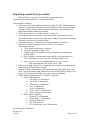
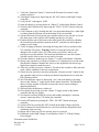
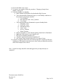
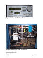
FC 1800 #1 Operational Instructions
For the Micro-Electronics Laboratory
At
University of Notre Dame
Department of Electrical Engineering
This user manual is not to be removed from room 244. This includes making copies.
A downloaded copy can be obtained from the web at the following link:
http://www.nd.edu/~ee/ndnf/
or contact Keith Darr for a copy of this manual.
Document owner: Keith Darr
Revision 3.0
11/3/08
Page 1 of 16
Purpose
The Model FC-1800 is an electron beam vacuum depositation/coater system.
The source chamber accommodates the high-voltage electron-beam sources,
wire feeders, shutter system, and substrate heaters. The source chamber is
maintained under vacuum at all times. This prevents contamination, which
typically occurs when a vacuum chamber is open to atmosphere. Design
features include easy access for loading and unloading and minimum volume
for fast cycling.
Reference
Operational Instructions written by Mark Richmond
Additional Equipment Required
None
Materials Required
Samples prepared as defined in user process flow
Protective Equipment Required
Latex Gloves
Safety Glasses
Engineering and/or Administrative Controls
Only authorized users may operate this piece of equipment
Training
To obtain training on this machine, please contact Keith Darr
(office 221, phone 1-5497, email)
Problems
For problems, clarification of procedures, or general information pertaining to this
machine please contact one of the following personnel.
Keith Darr 631-5497
[email protected]
Mark Richmond 631-6478 [email protected]
Mike Thomas 631-7493
[email protected]
In Case of Emergency, Please Contact Notre Dame Security at
911
MSDS’s can be located in the EE Department office or in Room 244 near the door
Document owner: Keith Darr
Revision 3.0
11/3/08
Page 2 of 16
Table of Contents
General Precautions
Standby Conditions
Depositing a Metal (Start Procedure)
To Change a Sample
Setup of Film Thickness Monitor
Figure 1: Vacuum and Valve Diagram
Figure 2: Film Thickness Monitor
Figure 3: Water Valves
Appendix A: Density & Z-Ratio
Appendix B: Tooling Factor
Appendix C: Authorized Users
Document owner: Keith Darr
Revision 3.0
11/3/08
Pg 4
Pg 5
Pg 6
Pg 9
Pg 11
Pg 12
Pg 13
Pg 13
Pg14
Pg15
Pg16
Page 3 of 16
General Precautions
This user manual will not be moved away from the FC1800 #1. This includes
making copies. Note: you can download it from the web (addresses on front cover) or
contact Keith Darr for a copy of this manual.
High Voltages are exposed when doors are open. Do not open the doors on this
unit unless instructed to do so by one of the above personnel.
Sweeping of the Electron beam is Mandatory. Failure to sweep the beam can
cause damage to the machine and cause you to lose your privileges to use this machine.
If any step does not respond, as it should, stop and put the machine into standby if
you can and contact someone for help. If unsure on how to get to standby mode safely,
leave the machine as it is and contact above personnel.
When appropriate the user will perform an alignment of the beam according to the
instructions in this manual. Beam will never contact the crucible liner or turret.
A logbook will be kept of all use of this machine. The log entry will consist of
your name, date, time of use, deposition metals used, and deposition thickness.
Gloves will be worn at all times when working inside the chamber of this
machine. Not wearing gloves can contaminate the vacuum system and possibly your
sample.
All users must be trained on the use of this machine and in the authorized user
list. If you are not on the list in Appendix C then you cannot use this machine.
A good vacuum practice is to have everything assembled, clean, and at hand
whenever you open the chamber. The quicker the chamber is closed, the faster it will
pump down to an acceptable and usable level. While the chamber is open, air and
moisture will adhere to all surfaces in it. These molecules then need to be pumped out of
the system, which can take quite a while if much contamination is allowed in. Therefore
take the time to do what you need to do but don’t walk off and leave the system open and
unattended for any length of time for any reason.
Verify sample holders are correct for this machine.
This system uses a Cryo-pump. This pump should never be turned off or exposed
to air/nitrogen when operating. Repeat offenders of this will lose their privileges to
operate this machine entirely. If this pump is turned off for any longer than a couple of
minutes please allow time for the pump to warm up and operate normally before use. If
the Cryo-pump is allowed to warm up, it will take at least 2-4 hours to warm up and
another 2-4 hours to pump down again.
Proper precautions need to be taken before anyone ever puts an arm thru the open
gate valve. This machine closes the gate valve in many conditions to protect itself from
damage. When the gate valve closes without warning it could seriously injure anything in
the way. Only properly trained personnel should ever put their hand below the open gate
valve. (Power outages, different operating modes, and even lab air interruptions cause the
gate valve to close.)
This machine is used by many of the lab’s Personnel. When done with this
machine please clean up your materials after yourself and leave the machine in standby
conditions.
Document owner: Keith Darr
Revision 3.0
11/3/08
Page 4 of 16
Standby Conditions
Refer to Figure #1 on page #12 for all indicator light locations.
(These conditions allow for the safest and best conditions for the machine, your
safety, and the best results for your research)
1. Main Chamber lid should be closed and under High Vacuum.
2. Valves that should be illuminated, open, or on in Standby conditions on the
automatic pump down controller.
a. “Cryo Isolation”
b. “Gate” should be in the “away” position.
c. “Cryo Pump”
3. Valves that should not be illuminated or open in Standby Mode.
a. “Roughing” Valve
b. “Fore Line” Valve
c. “Mechanical Pump”
d. “Vent” Valve
e. “Hi Vac” Position
f. “Home” Position
4. Shutter 2 should be on “Off” and the indicator should not be illuminated.
5. Chilled water Valves (on right side) should be off.
6. HV & Gun Controllers should be off.
7. Film thickness monitor should be on.
8. Chamber Light should be turned completely off.
Document owner: Keith Darr
Revision 3.0
11/3/08
Page 5 of 16
Depositing a metal (Start procedure)
Refer to Figure #1 on page #12 for all indicator light locations.
System Vacuum must be below 2e-6 for beam operations.
From Standby Conditions:
1. Fill out as much of the logbook located on top of the FC 1800. This information
needs to be completed for not only record keeping but also in case of emergency
with the facilities, machine failures, and personnel injury. This information is
helpful when dealing with many problems.
2. Follow the procedure to “Change a sample” on Page #9.
3. Switch the pocket to the position of your desired source by turning the rotary
switch on the Source selector to the appropriate setting. The pocket metal diagram
is located on the top left of control cabinet.
4. Follow the procedure, “Setup of Film Thickness Monitor” on Page #11.
5. Wait for the system vacuum to be below 2.0X10^-6 to continue.
If Ion Gauge reads 0.0:
a. Verify proper decade range is selected.
b. Verify the Ion gauge is turned “ON”.
c. Filament light is lit. (Found to the left and slightly lower than gauge
reading display.
d. If the Ion gauge is automatically turned off due to the movement of a
valve, such as the gate, the “Cryo Iso” will automatically close.
e. Open “Cryo Iso” valve by manipulating the “Cryo Iso” switch.
i. This is the light to the left of the “Away” light.
6. Pull up on the High Voltage Power Supply Breaker to turn it on. Located on the
front of the High Voltage Power Supply.
7. Open the front left main chamber door and turn the top right chilled water valve
to on. Turn on the bottom right chilled water valve as well. Refer to Figure #3 on
page #13 for an illustration of the water valves in the off condition.
8. Verify interlock light stacks on CV-14 HVPS Controller:
a. On the Gun Controller:
i. “Vac Gauge” is illuminated.
ii. “Vac Tank” is illuminated.
iii. “Gun Water” is illuminated.
iv. “Aux” is illuminated.
v. “Focus“is illuminated.
vi. “Gun 1 Tank 1” is illuminated.
vii. “Auto” will not be illuminated.
b. On the HVPS Controller:
i. “Power ON” is illuminated.
ii. “Triode Water” is illuminated.
iii. “Doors“is illuminated.
iv. “Air“is illuminated.
v. “PC Cards and key lock” is illuminated.
Document owner: Keith Darr
Revision 3.0
11/3/08
Page 6 of 16
9. Verify the “Emission Current” Control on the Electron Gun control is fully
counter-clockwise.
10. Turn High Voltage on by depressing the “HV ON” button on the High Voltage
Controller.
11. Verify the HV reads approx. 10KV.
12. Open the shutter by pressing down on “Shutter 2” switch on the Shutter Control.
13. Switch on the Filament on by depressing the “GUN 1 Fil ON” button on the gun
controller.
14. Verify filament is on by looking thru the view ports and making sure a white light
is coming from the filament area at the bottom of the vacuum tank.
15. Advance Emission Current on the gun controller until you are just able to see the
blue beam spot on the crucible when looking into the top view port.
16. Position the blue spot of the beam on the metal inside the crucible by adjusting
the lat and long beam position controls on the XY controller for the frequency
settings you are using.
17. Verify sweeping of beam by increasing the Long and Lat Freq. switches on the
XY controller if necessary. Warning: Failure to sweep the beam can cause
damage to the crucible, turret, FC 1800 system, your wafers, and/or your
privileges to use this machine. The beam spot should never come into contact
with the crucible walls or turret at any time or location.
18. Close the shutter by pushing up on “shutter 2” switch on the Shutter Controller.
19. Slowly ramp current over a couple of minutes to 2-3Angstroms per second on the
film thickness Monitor. Monitor this closely so the deposition rate does not go
higher than required to melt the source.
20. Allow the crucible to heat for 2 minutes. This allows the crucible to fully melt and
reach a stable condition for the best evaporations.
21. Slowly increase emission current by turning the “emission current” control on the
gun controller until you have reached your desired deposition rate as read on the
Film Thickness Meter.
22. Zero Film thickness meter by depressing “zero” and open shutter by pressing
down on the “Shutter 2” toggle switch on the shutter controller. This should be
done as closely together as possible to ensure the most accurate reading in
deposition thickness.
23. Wait until desired thickness is achieved.
24. Close shutter by pressing up on the “shutter 2” toggle switch on the shutter
controller and log your results.
25. Set emission current to ZERO by slowly and steadily rotating the “emission
current” control pot fully CCW on the gun controller.
26. Switch off Filament by pressing the “GJN 1 FIL OFF” button on the gun
controller.
27. Switch off HV by pressing HV OFF, located on the High Voltage controller.
28. Wait 10 minutes for turret and source to cool down from last deposition before
continuing to the next step.
29. Repeat step #3 thru step #28 for as many layers as you need.
30. Push down on the High Voltage Circuit Breaker on the CV-14 High Voltage
Power Supply.
Document owner: Keith Darr
Revision 3.0
11/3/08
Page 7 of 16
31. Close both chilled water valves.
32. To remove your samples, follow the procedure “Changing a Sample from
standby” on page #8.
33. Verify the machine is in Standby.
a. Main Chamber lid should be closed and under High Vacuum.
b. Valves that should be illuminated, open, or on in Standby conditions on
the automatic pump down controller.
i. “Cryo Isolation”
ii. Gate should be in the “away” position.
iii. “Cryo Pump”
c. Valves that should not be illuminated or open in Standby Mode.
i. “Roughing” Valve
ii. “Fore Line” Valve
iii. “Mechanical Pump”
iv. “Vent” Valve
v. “Hi Vac” Position
vi. “Home” Position
d. Shutter 2 should be on “Off” and the indicator should not be illuminated.
e. Right side Chilled water Valves should be off.
f. HV & Gun Controllers should be off.
g. Chamber Light should be turned completely off.
h. Ion Vacuum Gauge should read in the 10^-6 range or better.
34. Complete all logbook entries and verify that the logbook is completely filled out.
Signing out of the logbook states that you are done with your deposition and have
removed all samples, trash, and etc.
Note: Crystal Percentage should be read and logged after your deposition(s) are
completed.
Document owner: Keith Darr
Revision 3.0
11/3/08
Page 8 of 16
To Change a Sample:
GLOVE WILL BE WORN AT ALL TIMES WHEN WORKING INSIDE THE
VACUUM CHAMBER.
Refer to Figure #1 on page #12 for all indicator light locations.
1. Make sure the logbook is filled out as completely as possible and printed legibly.
2. Sample holders for this machine are unmarked, verify your sample holder.
3. Install sample onto holder if not done already or prepare sample to be put onto
sample holder. Normal usage users skip to Step #4 and lower chamber users go on
to 3A.
a. For full system opening, only authorized personnel should perform this. If
removing samples/equipment skip to Step #3e.
b. Verify the “Gate” is in the away position.
c. Close the “Gate Bypass” valve located behind and to the left of the water
valves. When activating this valve you should hear air being released.
d. Verify “Gate Bypass” is off by toggling the “Gate” Valve switch.
e. Close “Cryo Iso” valve by pressing down on the “Cryo Iso” switch.
f. Verify the “Cryo Iso” indicator light goes out.
g. Turn off the Filament of the “Ion Gauge” by depressing “Filament off”.
h. Verify the display for the “Ion Gauge” goes dark.
i. Go to Step #9.
4. Close the Gate valve by pressing down on the switch labeled “Gate”.
5. Verify the indicator light switches from “Away” to “Home”.
6. The “Cryo Iso” valve may have closed with the Gate valve, if it did then open the
Cryo Isolation valve by pressing up on the switch labeled “Cryo Iso”.
7. Close the “Hi Vac” valve by pressing down on the switch labeled “Hi Vac” on the
Automatic Pump Down Controller.
8. Verify the “Hi Vac” light illuminates and the “Home” light goes out.
9. Open the N2 “Vent” valve by pressing up on the switch labeled “Vent” on the
Automatic Pump Down Controller.
10. Verify the “Vent” light illuminates.
11. Allow a couple of minutes for the lid to come up to atmosphere pressure.
12. After the lid has been released from vacuum, the lid will pop up slightly. Pull up
and open the lid.
13. Make sure a new and clean plastic shield is in place for your deposition. As a rule,
Always verify there is a new shield installed when you put your sample in and
always change the shield after your deposition. These shields can be found just to
the right of the lid.
14. Install or remove samples and/or equipment in the FC1800. Note to Lower
chamber users, the signs for the material plaque are in with the sources and source
materials.
15. Verify the lid O-ring has not popped out at all. If it has then re-insert the o-ring
into the groove.
16. Pull down the lid and set it gently down on the O-ring.
17. Start mechanical pump by pressing up on the switch labeled “Mech Pump” on the
Auto Pumpdown Controller.
Document owner: Keith Darr
Revision 3.0
11/3/08
Page 9 of 16
18. Verify the Mechanical Pump light is illuminated.
19. Wait for 10-15 seconds for the mechanical pump down.
20. Close N2 “Vent” Valve by pressing down on the switch labeled “Vent” on the
Automatic Pump Down Controller.
21. Verify the “Vent” indicator goes out.
22. While holding down on the lid with a slight amount of pressure, open the
“roughing” valve by pressing up on the switch labeled “roughing” on the
Automatic Pump Down Controller. You should feel the lid “pull down” with the
vacuum almost immediately.
23. Verify the “roughing” indicator illuminates.
24. Close “roughing” Valve when the Thermocouple vacuum gauge on the Ion Gauge
Controller when the needle reads less than 50 microns by pushing down on the
switch labeled “Roughing” on the Automatic Pump Down Controller.
25. Verify the “Roughing” indicator goes out. Normal usage users skip to Step #25.
a. For full system opening, only authorized personnel should perform this. If
removing samples/equipment skip to Step #14e.
b. Turn off the Filament of the “Ion Gauge” by depressing “Filament off”.
c. Verify the display for the “Ion Gauge” goes dark.
d. Close “Cryo Iso” valve by pressing down on the “Cryo Iso” switch.
e. Verify the “Cryo Iso” indicator light goes out.
f. Open the “Gate Bypass” valve located slightly behind and to the left of the
Water Valves.
g. Verify the gate is still in “Away” position.
h. Go to Step #30.
26. Open “Hi Vac” by pressing up on the switch labeled “Hi Vac” on the Automatic
Pump Down Controller.
27. Verify “Hi Vac” indicator goes off and the “Home” indicator illuminates.
28. Shut off mechanical pump by pressing down on the switch labeled “Mech Pump”
on the Automatic Pump down Controller.
29. Open “Gate” by pushing up on the toggle switch labeled “Gate”.
30. Verify the “Home” indicator goes out and the “Away” indicator illuminates.
31. If installing a sample, return to page #6 and step #3. If removing a sample, return
to page #7 and step #32.
Document owner: Keith Darr
Revision 3.0
11/3/08
Page 10 of 16
Setup of Thickness Monitor:
This monitor is capable of retaining the characteristics of 9 different films.
However due to the many different films we use here at ND, the number of users this
machine has, and the amount of use it sees I suggest that you verify your information
every time you use this machine.
1. If you start using this monitor and it is displaying CRYSTAL 1, press
“Xtal life” button to bring it back to its normal view. This reading shows
the amount of life the Crystal has left.
2. Press “Zero” button to zero the monitor readings.
3. On the film thickness monitor. Press the “program” button.
4. Pick your film by rotating the knob to “Film 1”.
5. Press “Next” button. “Density” should be displayed. Density and Z-Factor
charts will be available in Appendix B and posted on side of the control
rack as well.
6. Rotate the knob until the density you want is displayed.
7. Press “Next” button. “Tooling” should be displayed.
8. Rotate the knob until the tooling for your sample holder is displayed.
Appendix A contains a list of tooling factors for the different sample
holders and will be posted on side of control cabinet as well. NOTE:
There will be specific sample holders for this machine and will be labeled
FC 1800 #2”. WARNING: Do not use the numbers from FC 1800 #1 or
#3, these numbers will be wrong for the setup in the FC1800 #2.
9. Press “Next” button. “Z-Factor” should be displayed.
10. Rotate knob until the Z-Factor you desire is displayed. Density and ZFactor charts will be available in Appendix B and posted on side of
control rack as well.
11. Press “Next” button. “Finl Thk” should be displayed. This step saves the
last setting of “Z-factor” into the program.
12. Press “Program” button to exit program mode. It is now ready for the
deposition.
13. Go to step 4 on page #6.
NOTE: The Film thickness monitor does not stop sampling the deposition when you
close the shutter. You will need to watch the monitor and log the thickness when you
close the shutter.
NOTE1: The Film Thickness Monitor should be on at all times.
Document owner: Keith Darr
Revision 3.0
11/3/08
Page 11 of 16
Figure 1: Vacuum and Valve diagram.
Document owner: Keith Darr
Revision 3.0
11/3/08
Page 12 of 16
Figure 2: Inficon Film Thickness Monitor.
Figure 3: Water valves in the off condition.
Document owner: Keith Darr
Revision 3.0
11/3/08
Page 13 of 16
Appendix A:
Density & Z Ratio Charts
Document owner: Keith Darr
Revision 3.0
11/3/08
Page 14 of 16
Appendix B:
Tooling Factors
Flat Bar:
U Bar:
289
180
Document owner: Keith Darr
Revision 3.0
11/3/08
Page 15 of 16
Appendix C:
Authorized Users
See logbook on the machine for accurate listing of users
Document owner: Keith Darr
Revision 3.0
11/3/08
Page 16 of 16